Original author: wegi1
Original project link: https://oshwlab.com/wegi1/km409-lc-ce-meter
# 新旧版本  # 量 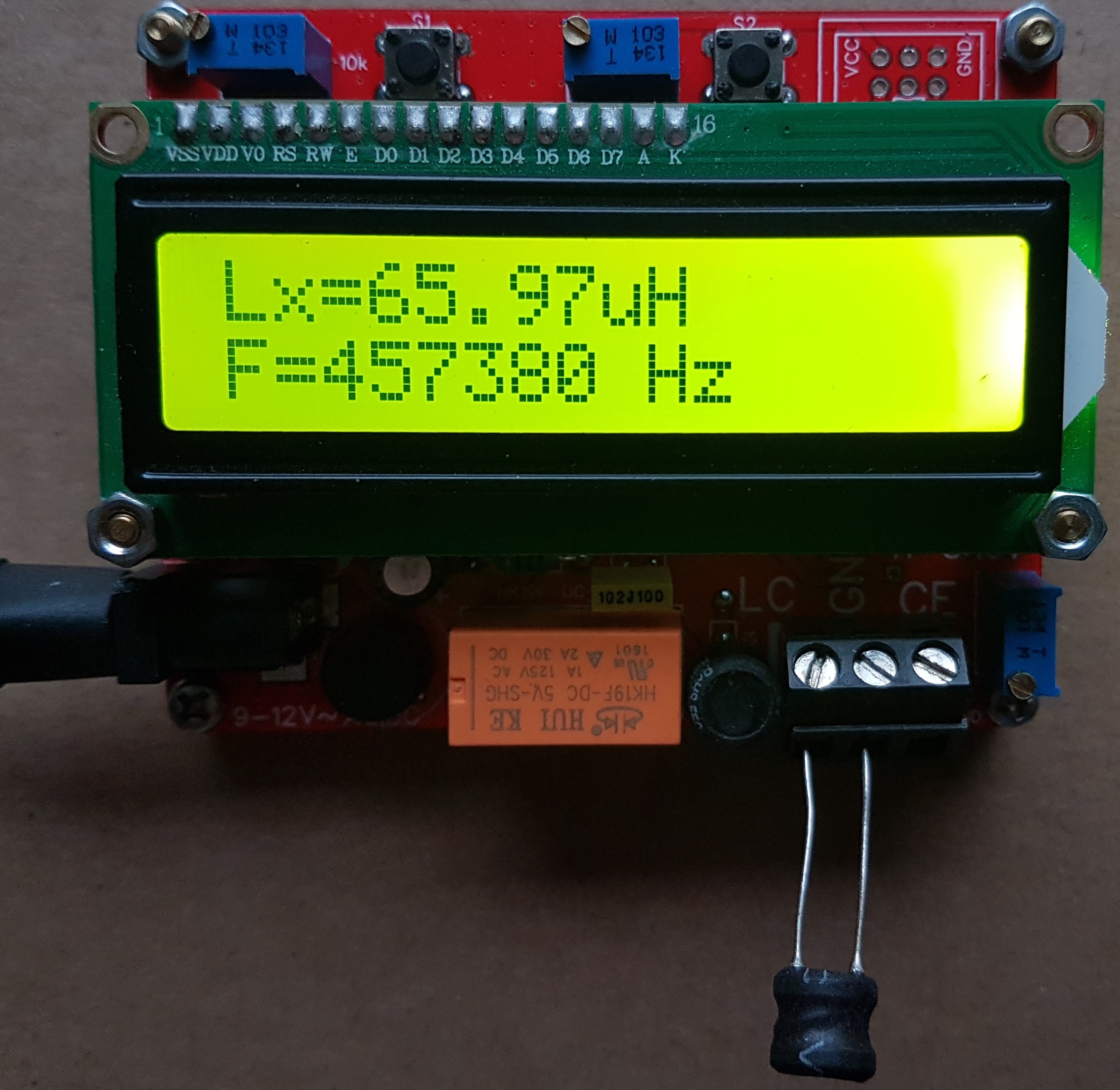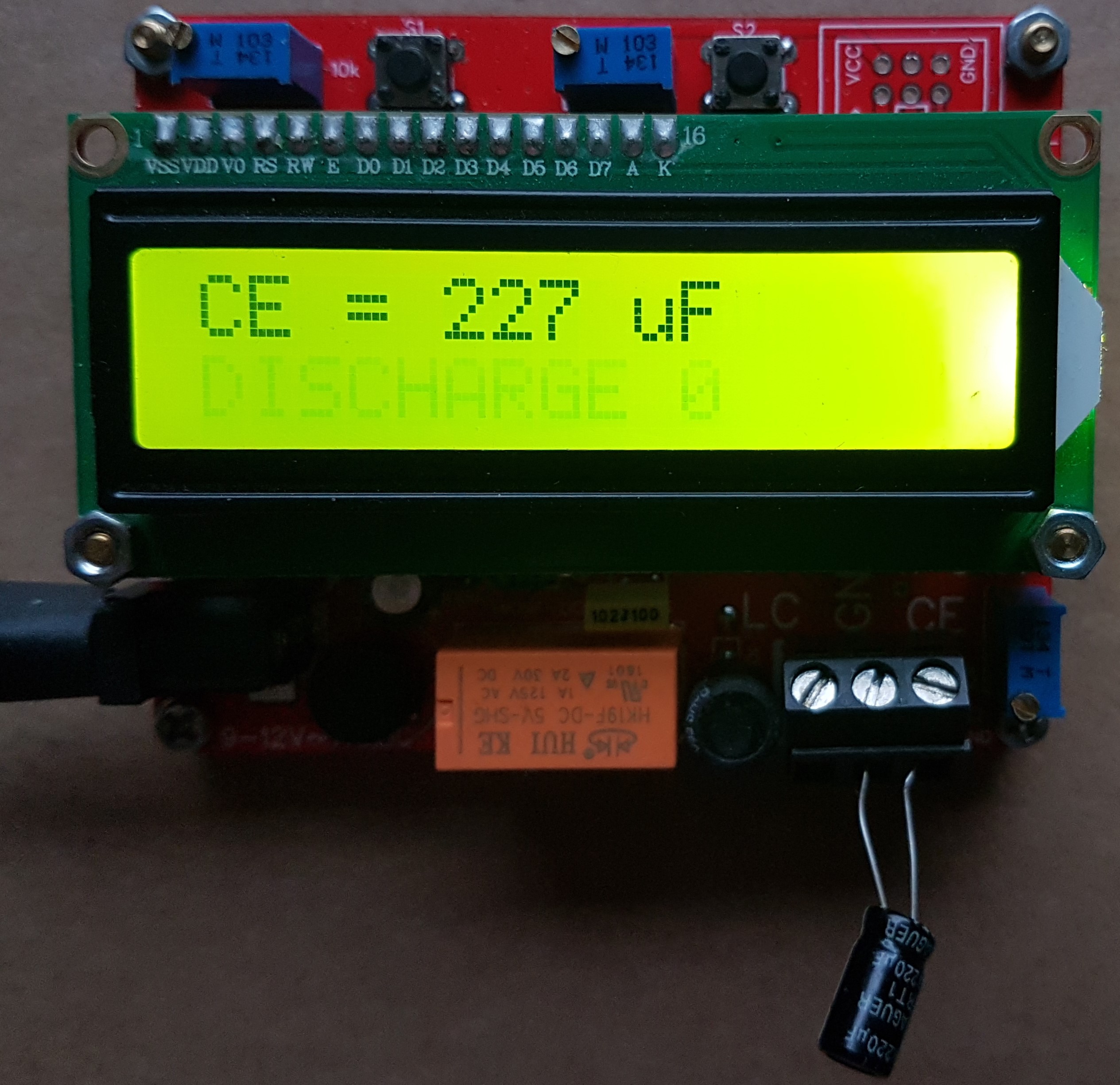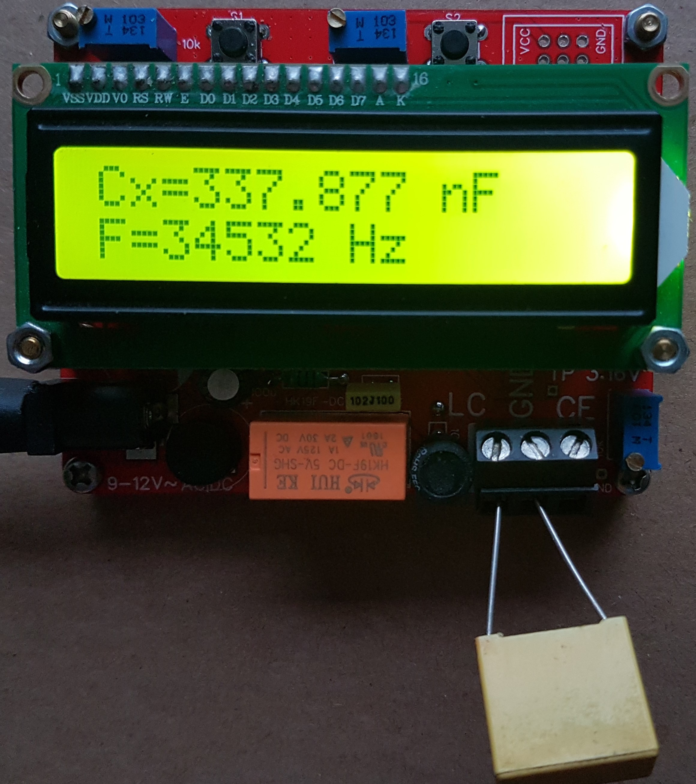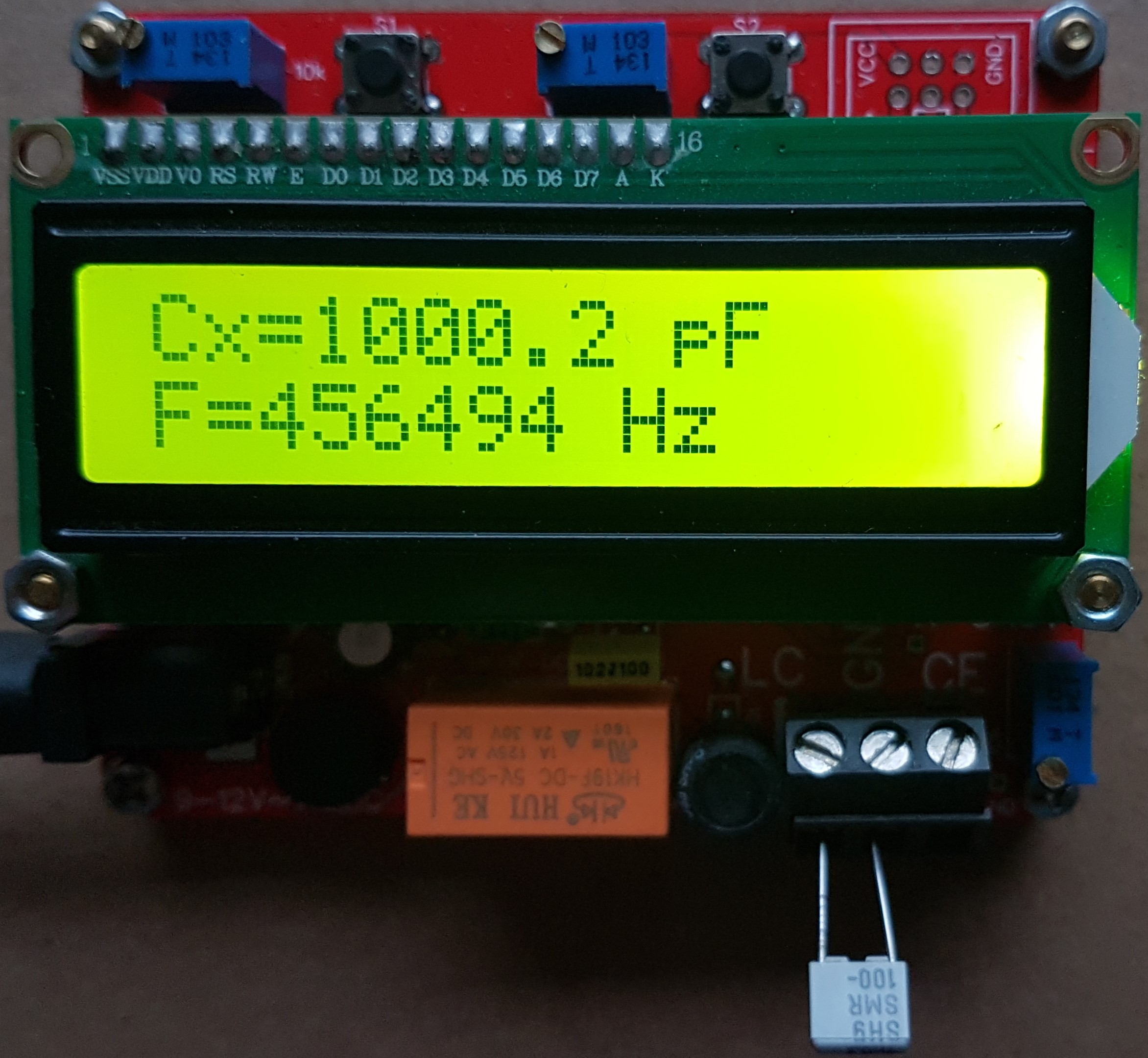 # PCB & ASSEMBLY 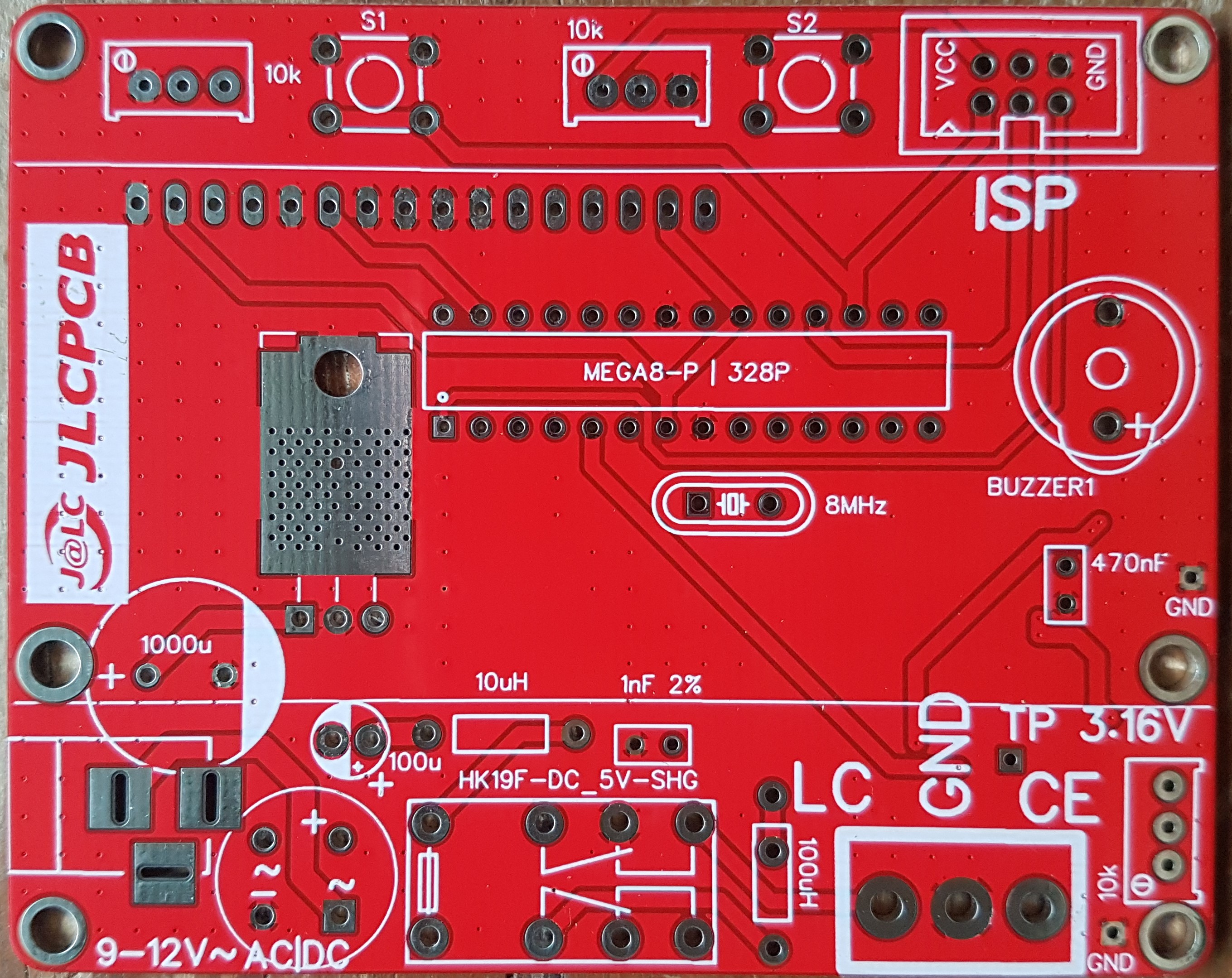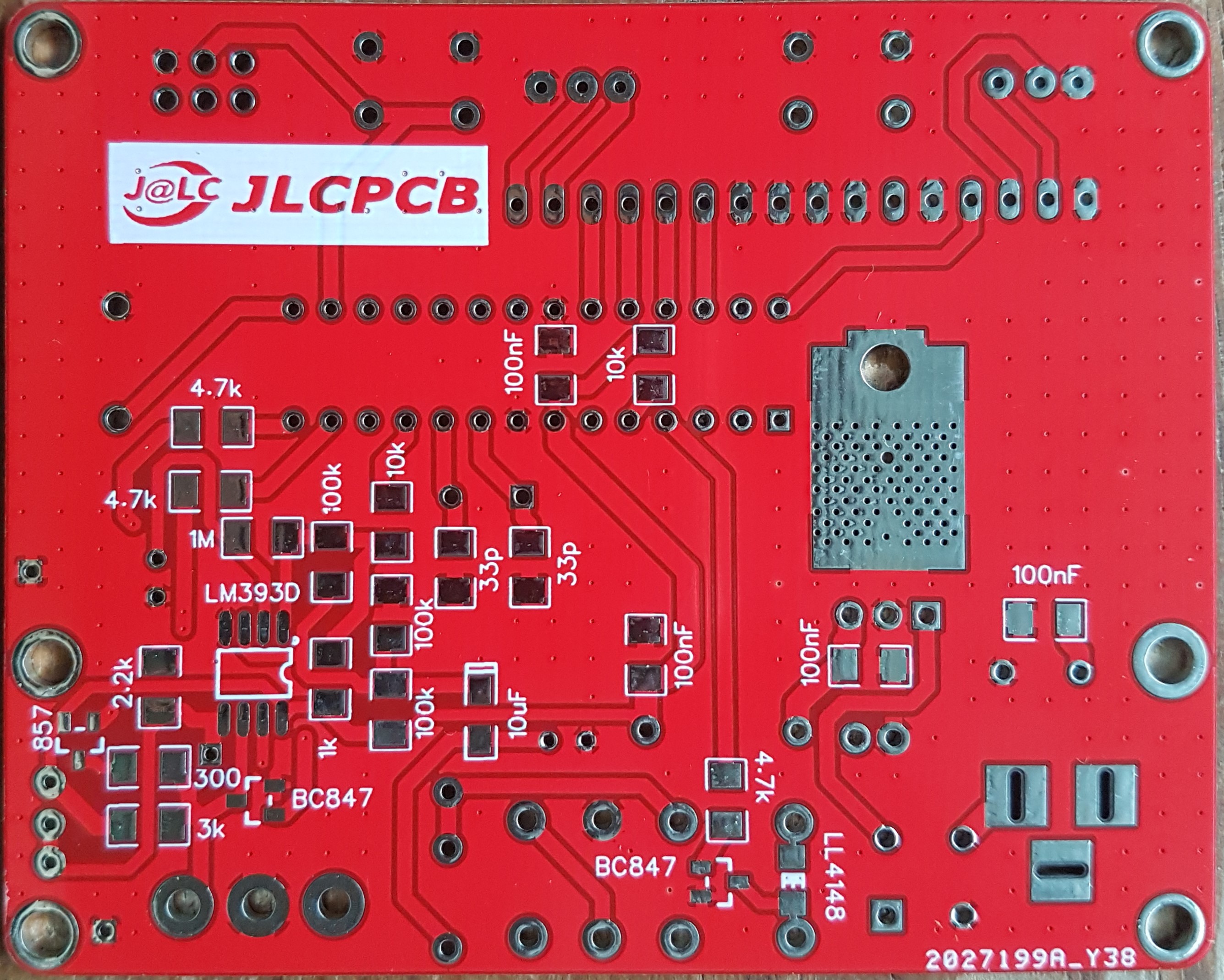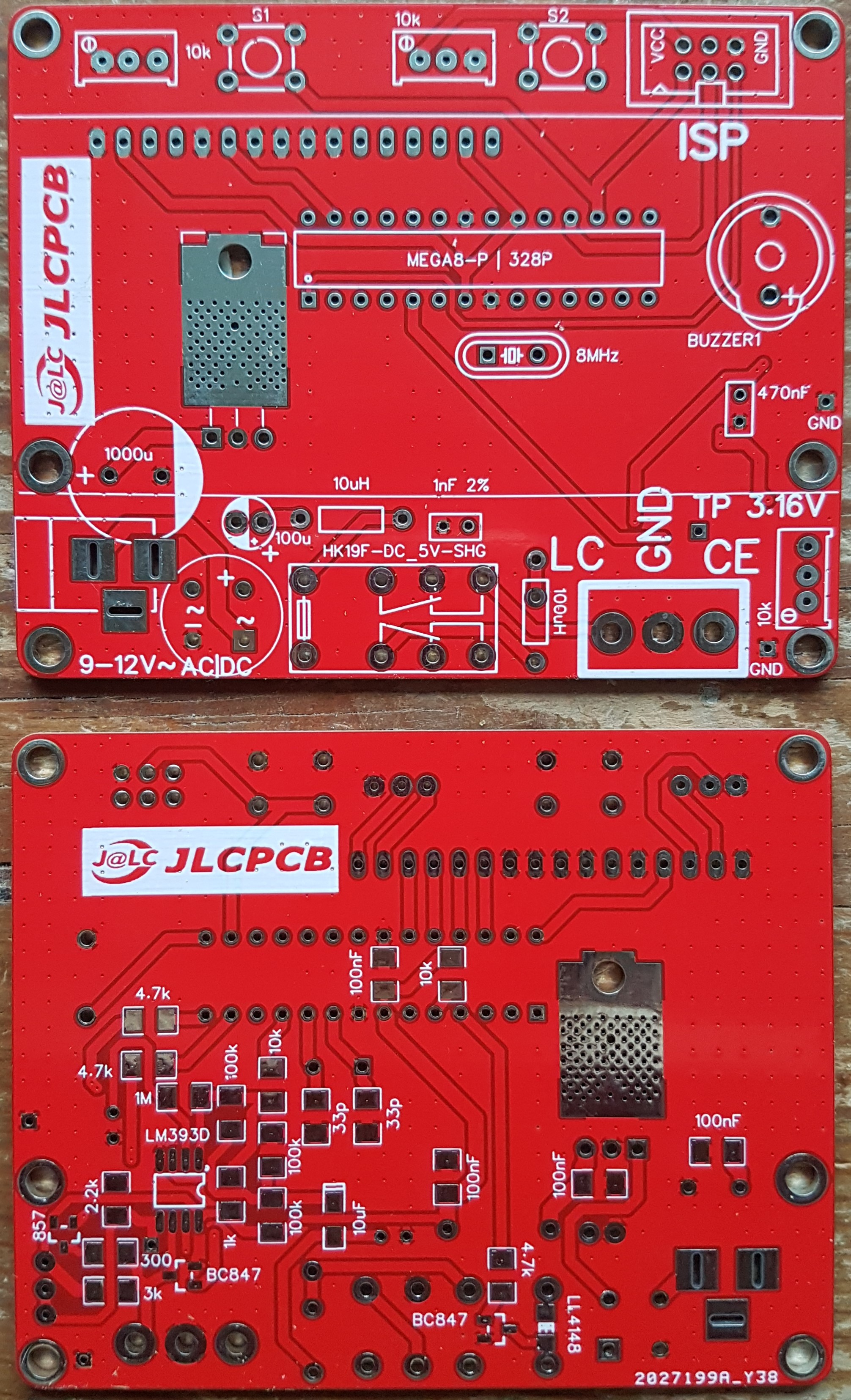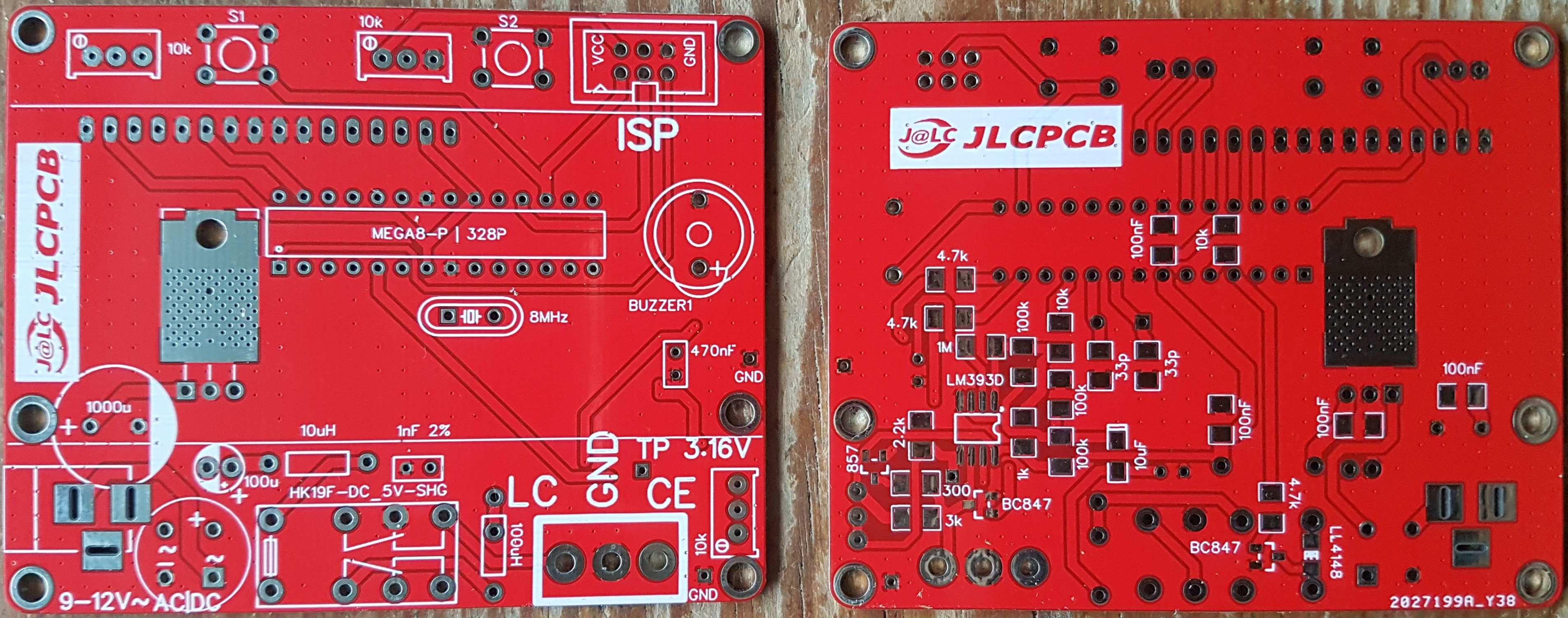 # OLD VERSION   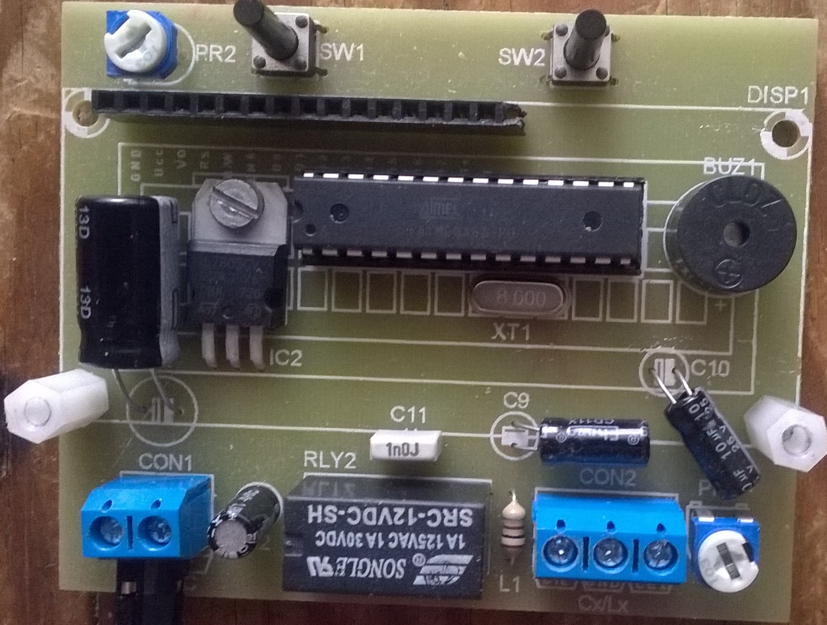 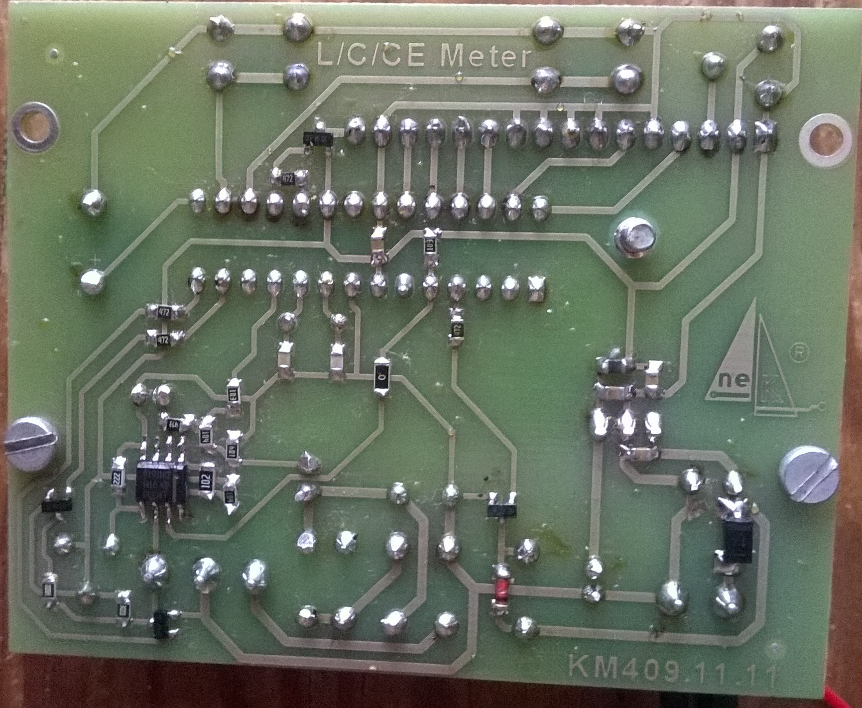 # NEW VERSION Some changes with power supply, better double side PCB, added diode bridge, replaced ARK connector to socket 2.1mm... 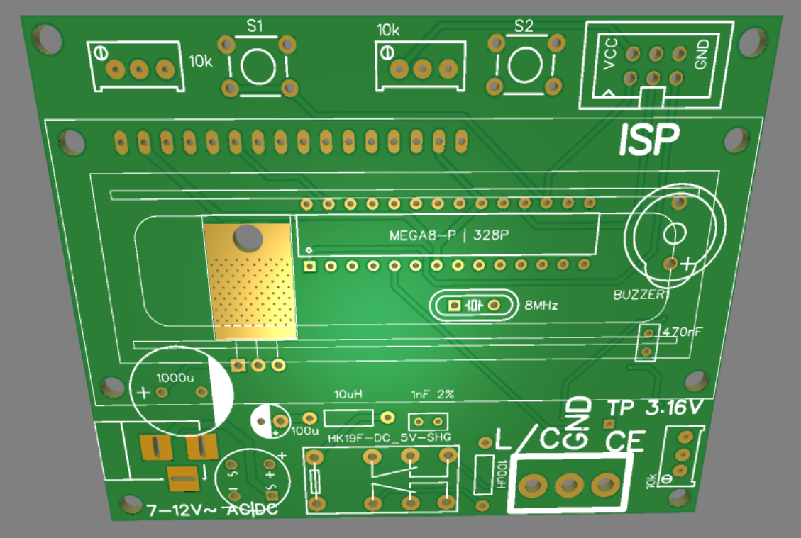 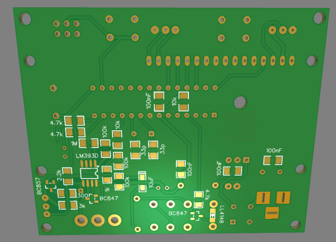 # 逻辑理念 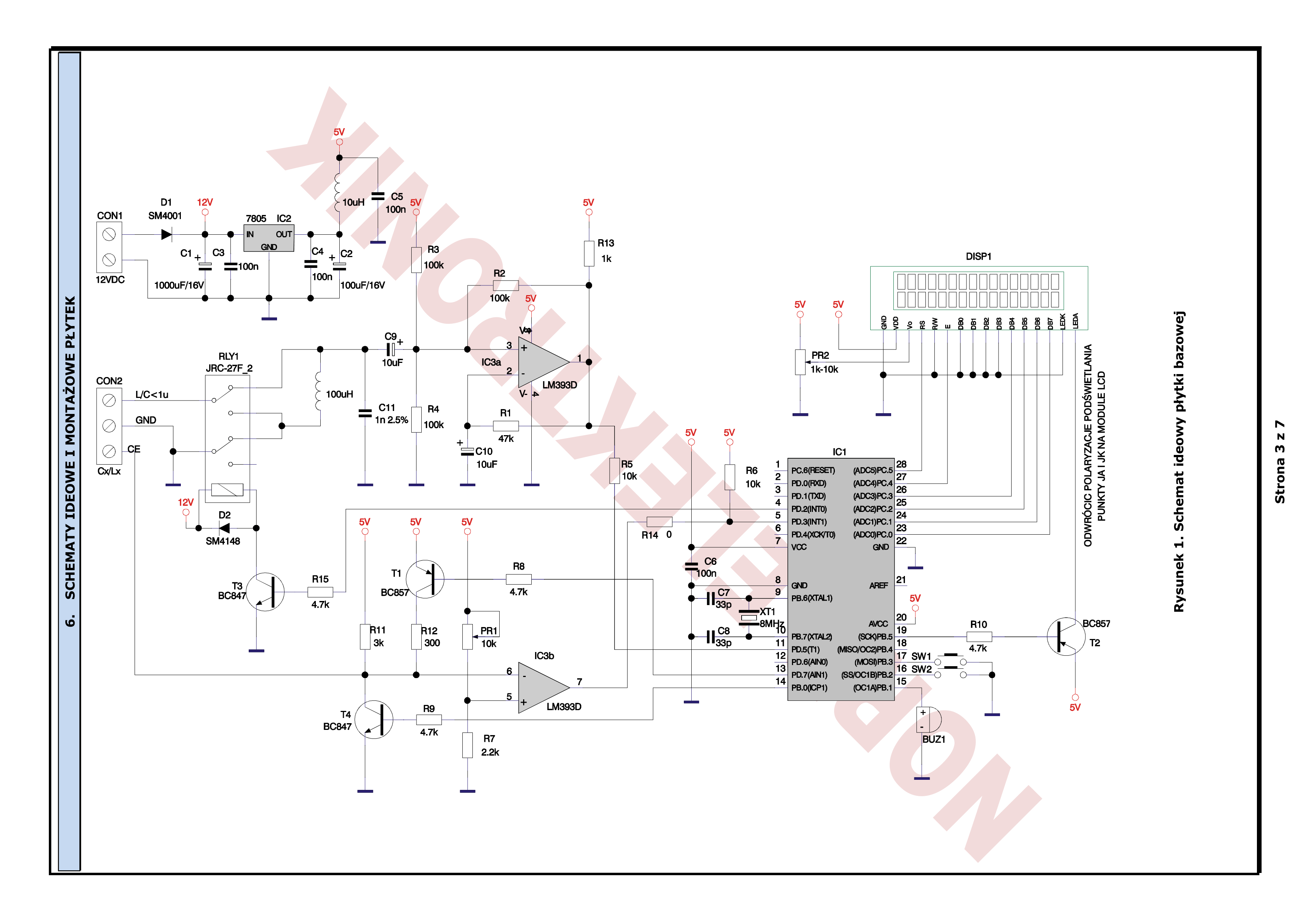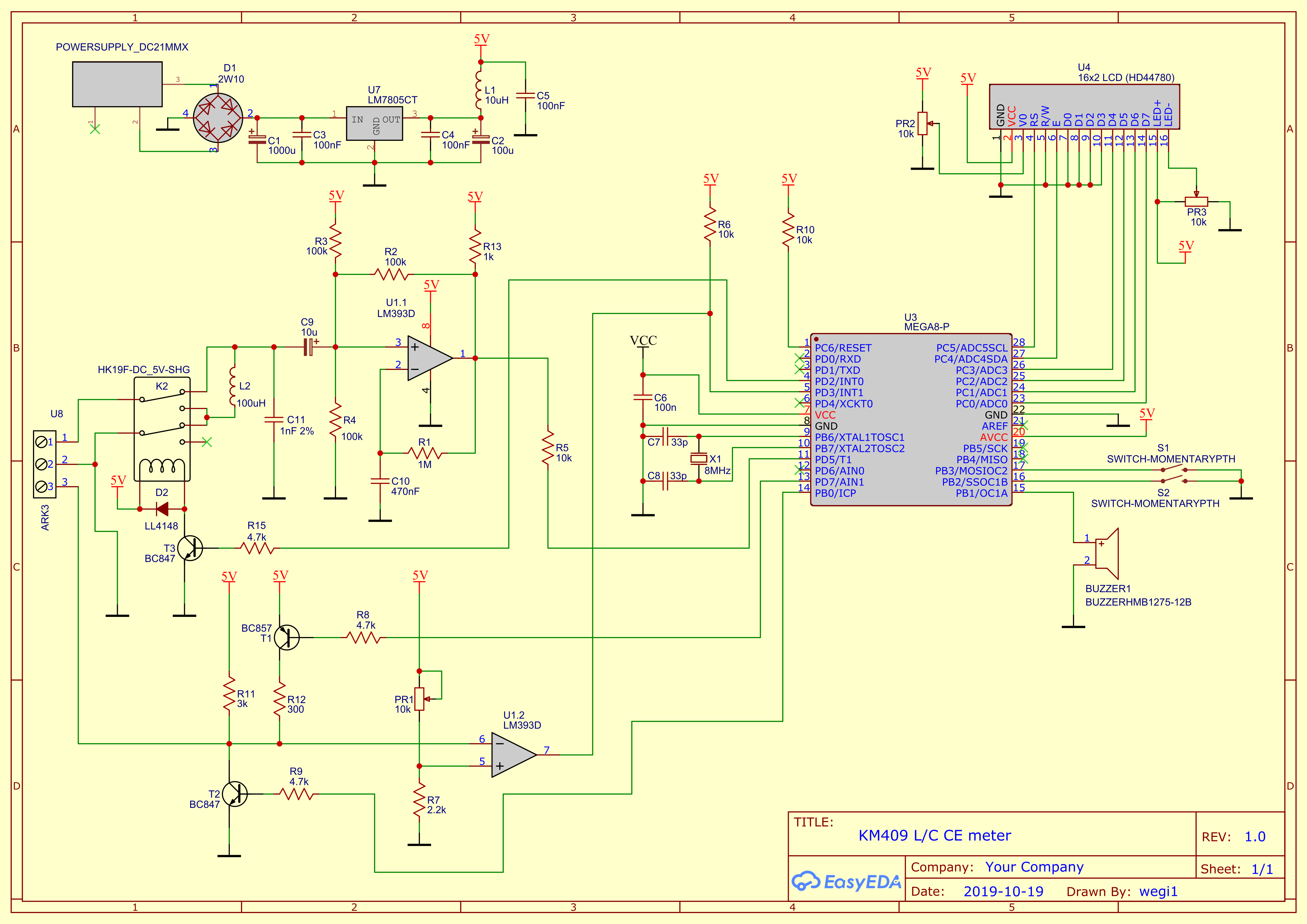 # 升降压计 **理论**电容+电感它们形成谐振电路。他在振动。振动的频率取决于容量和电感。当我们将谐振LC电路、线圈(串联到线圈)或电容器(并联到电容器)中时,谐振频率就会降低。 **练习(共振法)** L/C电路与LM393D比较器配合使用,输出从LM393D反馈回路到LC电路。因此,振动不会过期。比较器输出还向微控制器的输入引脚提供矩形信号。该信号具有LC电路的谐振频率。该信号的频率由微控制器测量。根据频率差了解LC发生器的电感值和容量,我们可以计算出连接到LC电路的电容或电感值。 **使用的公式**: 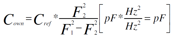 **哪里:** **整流罩** – LC 电路的电容 [pF] **Cref** - 添加到LC电路(发生器)[pF]的电容的参考已知值 **F1** – 添加 Cref 电容器 [Hz] **之前的** LC 电路的谐振频率 **F2** – 添加 Cref 电容器 [Hz] **后** LC 电路的谐振频率 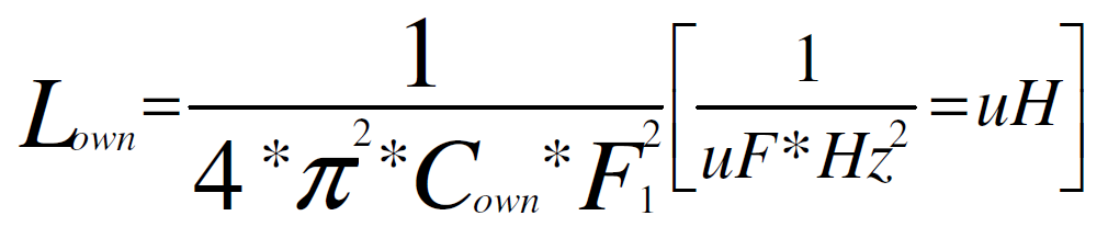 **哪里:** **Lown** – LC电路的自有电感(不添加任何其他电感器)[uH] **Cown** – LC电路的自有电容(不添加任何其他电容器)[uF] **F1** – 谐振LC电路的频率[Hz] 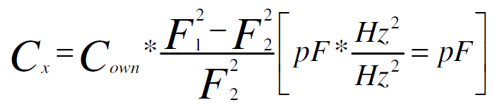 **哪里:** **Cx** - 是添加到LC电路(发生器)的未知电容值[pF] **整流罩** – LC 电路的自身电容 [pF] **F1** – 添加 Cx 电容器之前 LC 电路的谐振频率 [Hz] **F2** – 添加Cx电容后LC电路的谐振频率[Hz] 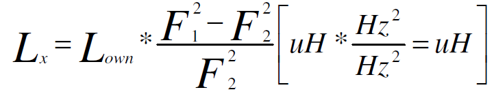 **哪里:** **Lx** - 是添加到LC电路(发生器)的未知电感值[uH] **Lown** – LC 电路的自身电感 [uH] **F1** – 添加Lx电感器[Hz]之前LC电路的谐振频率 **F2** – 添加Lx电感器[Hz]后LC电路的谐振频率 # 较大电容器的测量 - 电解电容器 **通过恒压充电到电容的时间。** ```
When we charging capacitor by constant voltage we can observed a curve of charge:
``` 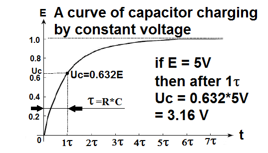 If it depends on the resistor and capacitor, we can see the charging time. These two values form a time constant called tau τ, its unit is seconds [s], so from the above graph we can get what is known: After one τ, the voltage on the capacitor gets 0.632 E value, so If our E has 5V, then after τ time the voltage across the capacitor will appear to be 3.16V. **Finally, knowing the value of R and measuring the charging time when we charge the capacitor to 0.632E, we can calculate the capacitor's capacity very easily. ** 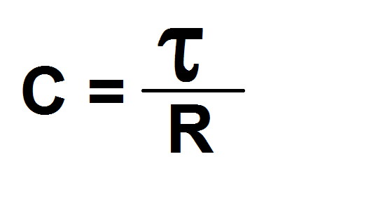 If we look at the diagram, notice that the capacitor can be charged by one or two parallel resistors RES1 and RES2. Therefore, the program uses one more formula: 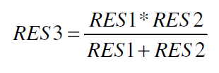 # WHAT YOU MUST DO TO GET A HIGH ACCURACY OF MEASUREMENT. Start with RES1 and RES3 soldering, and then measure and store their values. After assembling the whole and connecting the power supply, the VCC supply value should be measured, then the PR1 potentiometer should be set to 0.632 VCC at TP (arround 3.16V). # The FIRMWARE Wrote in assembler in two options – for ATmega8A or ATmega328P – why 328P? Cause I got a few unused Arduino so I don't need to purchase M8A After power on we can see three screens: ![010 AFTER RESET.PNG] (https://image.easyeda.com/pullimage/QJQC9sD4c036Ncu6qhpLEaGCPu9x6OeDu0uvPYdD.png) Honestly, after the first power on third screen going to calibrate menu, which I'll describe later. After reset we can put capacitor into the socket and measure capacitance . After pressed the left button we can see the L measure screen or the second one after put inductor into the **left socket**.  Next one press the left button invoke the third menu for CE measure: In the **right socket** we can do measure of electrolytic capacitors.  After this, the left button go back to small capacitors measure menu. Al the time by press right button we can invoke 7 specials menu. In this mode the right button select menu, and after the select any one by pressing left button execute it and go inside. How the program calculate capacitance: 1. Simply start charge of the capacitor and counting the clocks edges. 2. After charging capacitor program multiply by 125 value of counted clock edges, cause crystal have 8MHZ for translate to decimal relation to seconds. And divide by 10. 3. After that value is divided by RES2*100 (for better precision) or by RES3 (two parallely connected resistors RES3=RES1*RES2/[RES1+RES2] ) – result in [uF] or in 0.01 [uF] # MEASURE MENU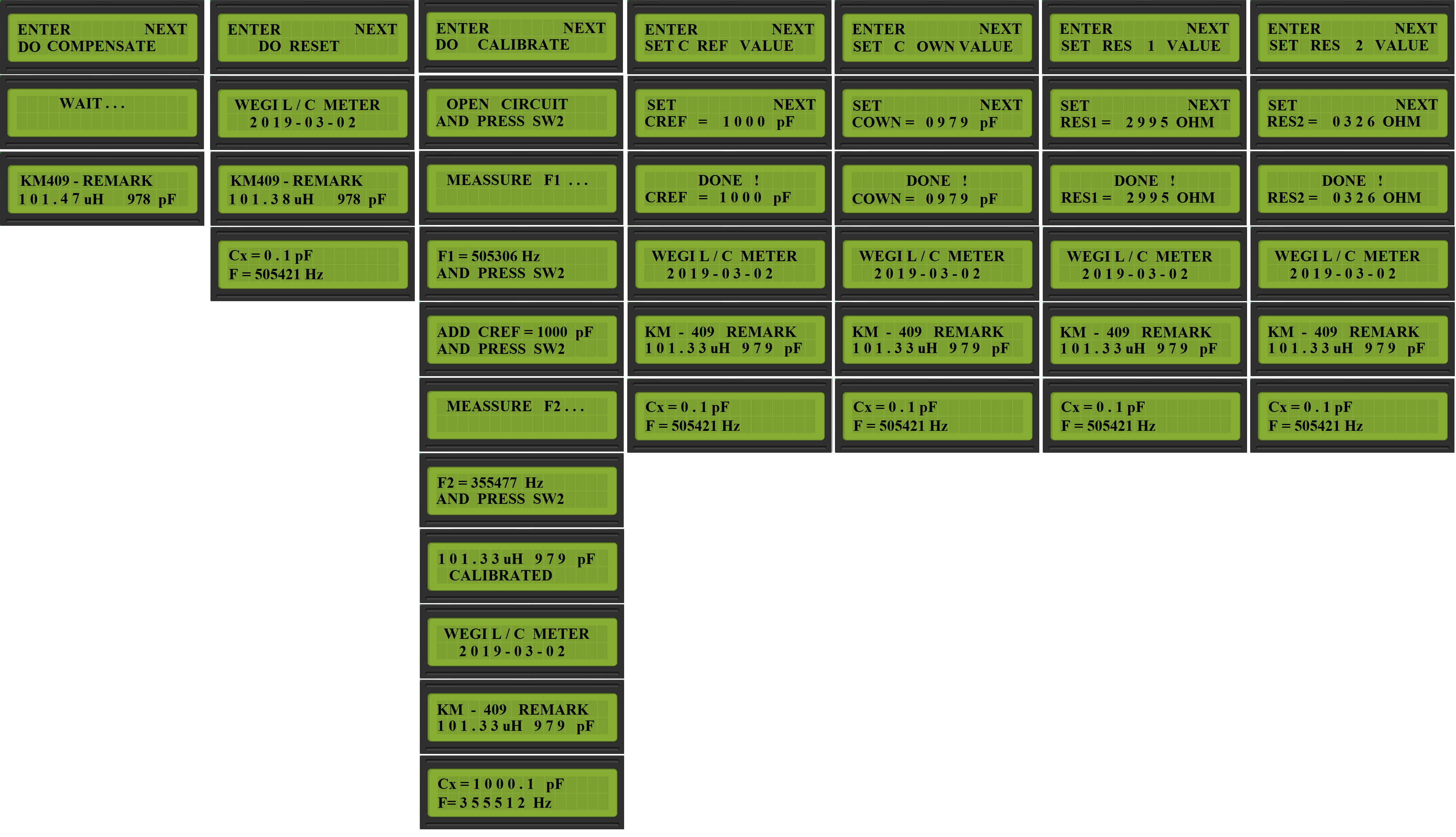 # MENU COMPENSATE: 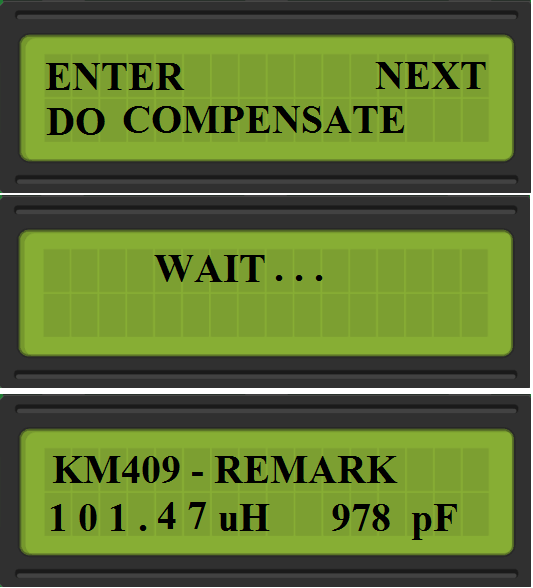 After select his menu program compensate the frequency value, which can be a bit floating depend from thermical values. And go back to last used menu of measure. # MENU RESET: 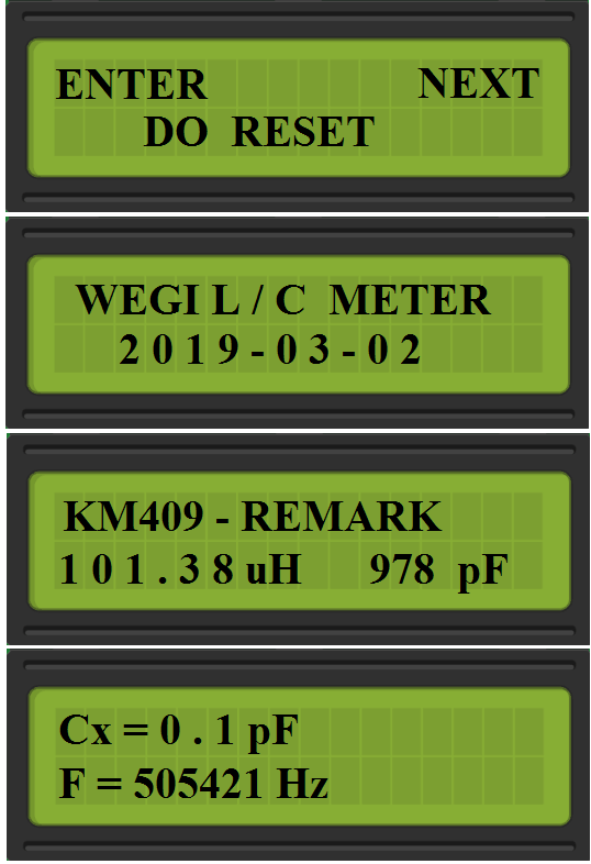 Simply restart of firmware, and lose the compensate value. # MENU CALIBRATE: 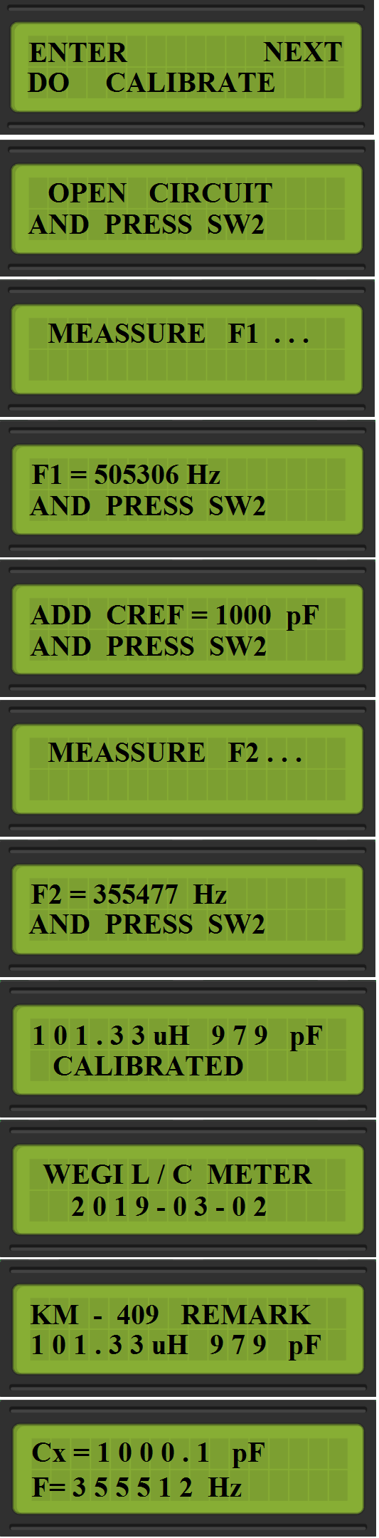 Most probably don’t need describe this menu, everything is on the following step by step screens. Note: You can choose in the next menu the reference value of the calibrate capacitor, which you’ll use. # MENU SET REF VALUE # – you can change the referential value your cap. for calibrate if you need. 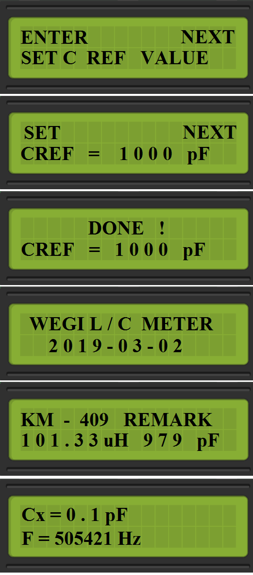 # MENU SET COWN VALUE: You can change the value of capacitor in LC generator circuit, after this the coil value will be recalculated. **In the last 4 menu you can set the value by pressing left button and right button for confirm.** 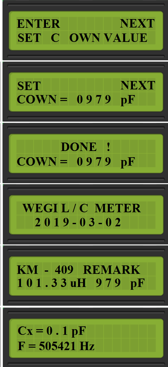 # MENU SET RES1 VALUE: Here you should set the RES1 value, which you measured after soldered RES1. 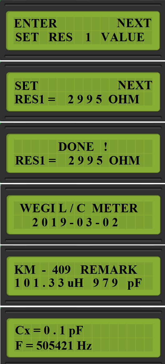 # MENU SET RES2 VALUE: Here you should set the RES2 value, which you measured after soldered RES2.  # 补充和好奇心 为了清楚起见,稍微展开第二个公式,并了解如何在整数上执行此操作。 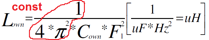 我们在这里得到了一个常量1/4PI^2,我们也除以[pF],所以我们可以像这样做sth: 100 000 000 000 000 000 000/4/Pi/Pi = 2 533 029 591 058 444 286 现在: 2 533 029 591 058 444 286 /F1/F1/C **因为 2 533 029 591 058 444 286 的值被放大了几十年,所以结果是 0.01 [uH] 等于 10 [nH] 的分辨率。** 例如,程序如何计算Cx或Lx,并且不会使用整数降低值: Cx = (Cown x [(F1 x F1)-(F2 x F2)])/F2/F2 因此,第一个结果 = (Cown x [(F1 x F1)-(F2 x F2)]) 足够大,可以除以 F2 的平方... # 已知问题: C9 10uF无法正常工作,断裂振荡 - 溶液 - 更换为非极化LM393D在焊接下可能损坏 - 断裂振荡 - 更换为新的。 二氧化碳

All reference designs on this site are sourced from major semiconductor manufacturers or collected online for learning and research. The copyright belongs to the semiconductor manufacturer or the original author. If you believe that the reference design of this site infringes upon your relevant rights and interests, please send us a rights notice. As a neutral platform service provider, we will take measures to delete the relevant content in accordance with relevant laws after receiving the relevant notice from the rights holder. Please send relevant notifications to email: bbs_service@eeworld.com.cn.
It is your responsibility to test the circuit yourself and determine its suitability for you. EEWorld will not be liable for direct, indirect, special, incidental, consequential or punitive damages arising from any cause or anything connected to any reference design used.
Supported by EEWorld Datasheet
EEWorld
subscription
account

EEWorld
service
account

Automotive
development
community

Robot
development
community

About Us Customer Service Contact Information Datasheet Sitemap LatestNews


Room 1530, 15th Floor, Building B,
No.18 Zhongguancun Street,
Haidian District,
Beijing, Postal Code: 100190
China
Telephone: 008610 8235 0740
 京公网安备 11010802033920号

 VTB2-4B0


