

Red roses: Passion, love for you. I love you, I am in love, I hope to have a passionate love with you.
Blue roses: Miracles and impossible things, I hope you are happy. White roses
: Innocence, purity, respect, humility. Yellow roses:
Unfaithfulness, jealousy, joy, happiness, apology. For friendship, yellow roses represent pure friendship and good wishes. For love, yellow roses are a kind of ominous thing, because it represents jealousy, lovelorn and fading love, and even an expression of jealousy.
Purple roses: Melancholy, fantasy, love to dream.
Black roses: Noble, mysterious you are my goddess; you are the devil, and you belong to me.
Green roses: Pure and simple, youthful forever, I only love you.
Rose (red + white): Shared.
Rose (red + yellow): Happy.


BOM Download
PCB_Rose_2022-09-24.pdf
PCB_rose_2022-09-24.json
Rose_2022-09-24.pcbdoc
Gerber_rose_2022-09-24.zip
61468
MicroPython Electronic Load
Introduction: Active DC constant current electronic load, design power 100W, ESP32 master control, MicroPython programming.

When the electronic load is working, there are many risks of possible injury, disability, and death, such as electric shock, high temperature burns, and physical damage caused by high-speed rotation of the fan. Please operate in strict accordance with safety regulations and provide adequate protection. Minors should operate with the assistance of their guardians. Making and using this product by yourself means that you have sufficient awareness of safety risks, and any losses and consequences caused are at your own risk. The platform and the author do not bear any legal responsibility.
Design description:
1. Use ESP32 master control and use MicroPython programming to realize the constant current function of 100W electronic load;
2. Input voltage -DC12V;
3. Load input voltage: 1~30V, maximum constant current value: 6A;
4. The maximum design power is 100W, which is related to the heat dissipation;
5. This design is used for MicroPython learning applications. Many functions have not been realized yet (constant voltage/constant power/battery discharge, etc.), and some small details are not perfect. Welcome everyone to improve together;
6. The original design uses AD software, the schematic is imported into the standard version, and there are problems with PCB import. Download is provided.
It's an old habit, I use whatever I have at hand: a discarded industrial power supply/775 cooling fan/LCD1602, with I2C interface board, the finished picture is as follows:

After disassembly, the assembly picture is as follows:


The actual load interface is displayed as follows:

Schematic diagram description:
The device DC5.5 power socket, input 12V power, add reverse protection:

The 12V power supply is converted to 5V output by the MP1584 DCDC power module to provide power for the device, and the USB 5V power input is only used for compiling or burning programs. 3 LDOs provide power for the back-end processor and analog circuit respectively:

The INA229 current detection chip and the OPA2340 op amp together form a constant current feedback circuit. A few more anti-reverse diodes are added. R39 and the adjustable resistor do not need to be soldered: The

MCP4725 DAC chip outputs a comparison voltage to set the output current:

Instructions for use:
1. Use the firmware written in MicroPython. Please refer to the online tutorial to configure the MicroPython environment of ESP32: Quick Start MicroPython Development ESP32
2. Upload all the Python codes in the attachment to ESP32 and run ESP_ELD_V2.1.py.
3. The rotary encoder is used to control the constant current value, which can be controlled with or without load.
4. The button controls the load switch.
ESP32_ELD_PCB_V2.pdf
ESP32_ELD_Python.7z
ESP32_ELD_2107_V2.7z
ESP32_ELD_2107.CSV
BOM Download
Schematic_MicroPython Electronic Load_2022-09-24.pdf
SCH_MicroPython Electronic Load_2022-09-24.json
MicroPython Electronic Load_2022-09-24.zip
61477
#The7thLiChuangElectricityContest#JiaLiChuangSummer Training Camp 2022
Introduction: Using National Technology N32G430 series chip as the main control, official routine.
Note: * is a required field,
please fill it in during the registration stage↓
* 1. Project function introduction
This is a USB power meter, which uses the National Technology N32G430 series chip as the main control and can measure voltages of about 5V
* 2. Project attributes This
is the first time that the board I drew is made public, and I drew it following the official example
* 4. The hardware part
uses the National Technology N32G430 series chip as the main control, which is responsible for sampling voltage and current, performing simple power consumption calculations and driving the 0.91-inch OLED.
The current sampling part uses the INA199 chip, and the sampling resistance is 10mΩ. The current I can measure is about 2.2A.
It is drawn using the EasyEDA standard. If you want to add functions and shells later, you will switch to the professional version.
* 5. Software part
The software part uses Keil5 for programming, mainly referring to the official EasyDone of National Technology. Because the OLED connection is different from the official example, I2C is modified in the program.
* 6. BOM list

Except for the screen, which was not bought at EasyDone, all other components were bought at EasyDone Mall, which is very cheap and easy to use. *7. I forgot to print
the competition LOGO verification PCB. I will print it on the second version next time. The engineering PCB has the competition logo added!! * 8. Demonstrate your project and record it as a video to upload . I haven’t recorded the video yet because I just started college and have a lot of things to do. I can only record it later.
File package.rar
BOM Download
PCB_PCB_#The 7th Lichuang Electronic Competition#Jialichuang Summer Training Camp 2022_2_2022-09-24.pdf
PCB_PCB_#The 7th Lichuang Electronic Competition#Jialichuang Summer Training Camp 2022_2_2022-09-24.json
PCB_#The 7th Lichuang Electronic Competition#Jialichuang Summer Training Camp 2022_2_2022-09-24.pcbdoc
Gerber_PCB_#The 7th LiChuang Electronic Competition#Jialichuang Summer Training Camp 2022_2.zip
Schematic_#The 7th Lichuang Electronic Competition#Jialichuang Summer Training Camp 2022_2022-09-24.pdf
SCH_#The 7th Lichuang Electronic Competition#Jialichuang Summer Training Camp 2022_2022-09-24.json
Sheet_1_2022-09-24.schdoc
61487
Shashasha is the little bitch
Introduction: This is a project written in Python using ESP8266, using trembling servos to express emotions, and a writing clock with a small wish - Xiaojian.
The training camp is over, but Xiao Jian is still not finished. Xiao Jian's master will slowly finish it, everyone please be patient, be patient.
The model is finished and is in the attachment. The master replaced Xiao Jian with 8266 and drew a new board.

Xiao Jian's mood is like a poem.
Slowly,
Xiao Jian began to understand
that robots also have their own moods and
no longer need to please anyone.
Xiao Jian's inferiority complex
no longer holds tears.
The master gave Xiao Jian a piece of
bright acrylic .
Those who look down on Xiao Jian
are not in Xiao Jian's eyes. Xiao Jian returns
those who are good to Xiao Jian
with tenderness .
When Xiao Jian misses you,
he writes every minute of thinking about you
in his heart -
that piece of bright acrylic .
Xiao Jian's body is a plastic servo.
Abandoning 9685 ,
the simple Xiao Jian does not accept extra parts and
refuses metal servos .
The poor Xiao Jian does not bear the fate of wealth .
Use SG90 to support Xiao Jian's soul.
Will PWM direct control shake?
Will plastic gears shake?
Shake it! ... The exhaustion of running around , the torment of thinking hard, the despair of racking one's brains , let the master execute the program in his head like a machine? It's really the failure of the machine, the sadness of mankind . Don't write C programs to prevent the master's brain from burning out. Let the master be happy. Master, use Python. Xiaojian's wish is small but persistent. I, Xiaojian, am a robot as happy as Python . My PIGU was made by the master. Oh no! My PCB was made by the master. My model was drawn by the master. My program was written by the master. The master posted everything about me in the attachment below. From then on, I had a small wish - I hope you can create another me in another corner of the world . ----------- The master spends his days like this. Xiaojian's construction progress . Xiaojian's master has finished soldering the PCB. Xiaojian's master has finished drawing Xiaojian's body. Xiaojian's master, please give Xiaojian's body model first. Xiaojian's master, the program has not been written yet, so he cannot participate in the evaluation. Xiaojian's master will slowly build Xiaojian's soul. Xiaojian's master, I hope everyone will not scold you, and wait patiently. Xiaojian's body Xiaojian's body is assembled in FreeCad. There are a total of 11 parts , including the servo and battery. The PCB in the FreeCad library is exported using the LiChuang professional version. The remaining 8 are drawn by the owner . There is also an acrylic plate, 5x10mm. Don't print it. Ask the black-hearted boss to buy it. 2 yuan for 10x10mm, free shipping. Ask the boss to cut it. Cut it for 5 pieces by yourself, free of charge.
Xiaojian's body model.zip
Assembly and debugging.zip
STL printing model.zip
BOM Download
PCB_PCB_Robot Xiaojian_2022-09-24.pdf
PCB_PCB_RobotXiaojian_2022-09-24.json
PCB_Robot Xiaojian_2022-09-24.pcbdoc
Gerber_PCB_RobotXiajian.zip
Schematic_Shashasha is the little bitch_2022-09-24.pdf
SCH_Shashasha is the little bitch_2022-09-24.json
SCH_Robot Xiaojian_2022-09-24.schdoc
61497
FM1922570CT6-00 module
Introduction: FM1922570CT6-00 module
The reference program needs to be used with this core board: The STM32G030F6P6 core board
module reserves the CS pull-down resistor R4. If the CS function is not needed, an IO can be saved.
The module reserves the backlight switch. When the BL pin is floating or at a high level, the backlight is turned on, and when the BL pin is at a low level, the backlight is turned off. If there is no need to turn off the backlight, you can solder R1 instead of Q1, R2 and R3.
G030_FM1922570CT6.hex
BOM Download
PCB_PCB_FM1922570CT6-00 module_2022-09-24.pdf
PCB_PCB_FM1922570CT6-00Module_2022-09-24.json
PCB_FM1922570CT6-00 module_2022-09-24.pcbdoc
Gerber_PCB_FM1922570CT6-00 module_2022-09-24.zip
Schematic_FM1922570CT6-00 module_2022-09-24.pdf
SCH_FM1922570CT6-00Module_2022-09-24.json
Sheet_1_2022-09-24.schdoc
61503
#The 7th Lichuang Electric Competition# USB power meter based on N32G430
Introduction: USB power meter with wide input voltage based on N32G430 design
1. Project function introduction
The USB power meter based on N32G430
supports 4.5~24V wide voltage input.
It supports measuring the voltage, current and power of the VBUS line, and can also measure the voltage of D+ and D-.
2. Project attributes
are designed by yourself.
3. Open source agreement
CC-BY-NC-SA 3.0
4. Hardware part
The MCU adopts National Technology N32G430K8L7, LQFP32 package.
The monitoring chip adopts Texas Instruments INA226, which supports a maximum input voltage of 36V. It supports measuring voltage and current, and automatically calculates power. Use I2C to output the measurement results.
The digital power supply adopts a DC-DC solution to power the MCU and OLED. The high efficiency of DC-DC can prevent the PCB from heating up when the high voltage difference occurs, which affects the measurement results. The chip uses TMI3359, which supports a maximum input voltage of 30V. A 4.7uH inductor in CD32 package is used to ensure that the inductor does not heat up. I personally like DC-DC with a higher switching frequency, so that smaller capacitors and inductors can be selected to reduce the area of the circuit.
The analog power supply adopts LDO solution to power INA226. The output voltage fluctuation of LDO is smaller, which is more suitable for precise measurement. In addition, INA226 is a low-power component, and it will not heat up even if the voltage difference is relatively large. The chip uses SE8533, which supports a maximum input voltage
of 36V. The input capacitor uses a 50V MLCC capacitor. Because MLCC is a ceramic capacitor, it will deform to a certain extent as the voltage increases, resulting in a decrease in capacity. Therefore, the withstand voltage value of MLCC is generally selected to be 2~3 times the maximum input voltage.
The resistance of the current sampling resistor is 10mΩ. A smaller resistance value can minimize the voltage drop generated on this resistor. A lower temperature coefficient can ensure that the resistance value of the resistor changes less when the current is large, thereby improving the linearity of the measurement. The resistor selected this time has a 1% accuracy, a 2W power, and a temperature coefficient of ±70ppm/℃.
The display uses a 0.91-inch OLED screen with a resolution of 128x32 and a communication protocol of SPI.
In terms of interfaces, the input end is a USB-A male and a USB-C female, and the output end is a USB-A female and a USB-C female. Using USB-A can eliminate the need for data cables, while two USB-Cs take into account the PD protocol and the possibility of extending the cable during use to place the power meter in a position that is convenient for observation.
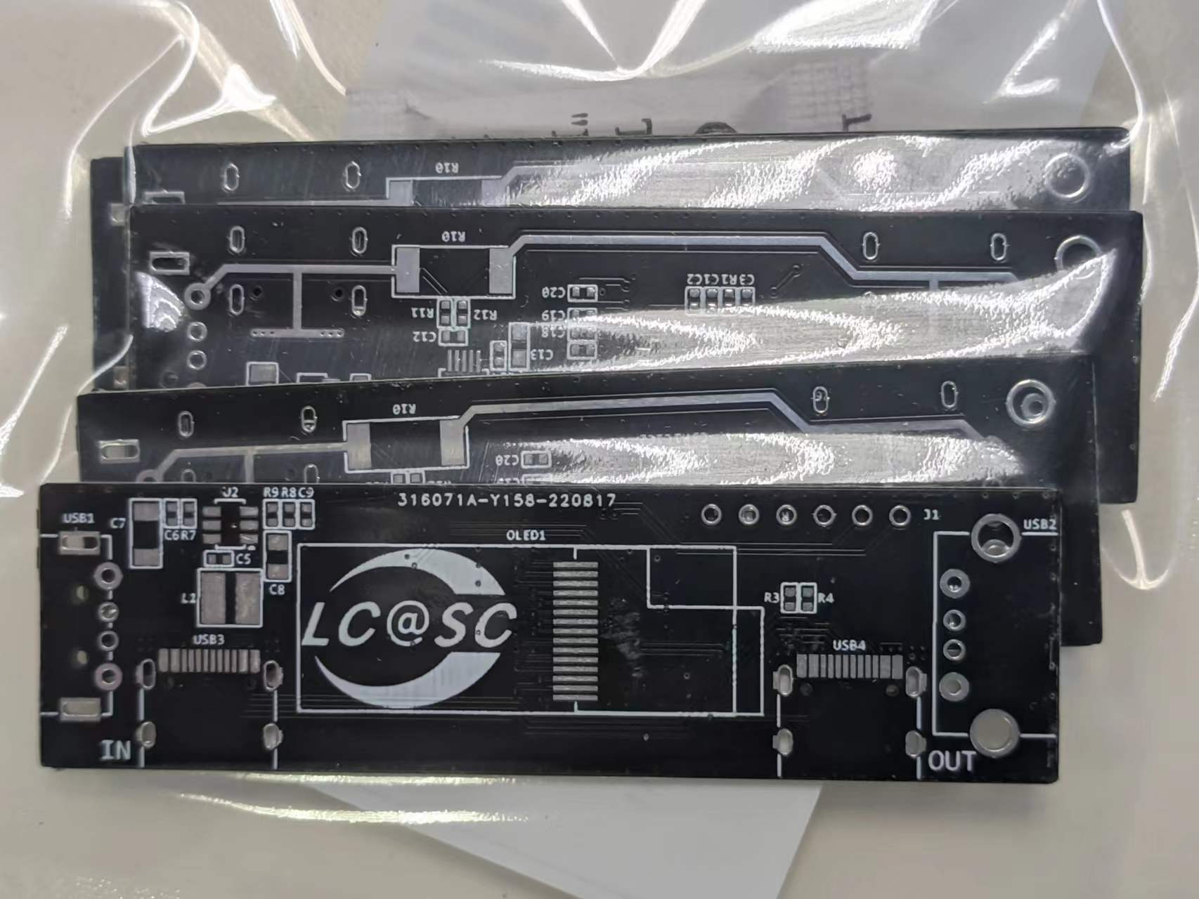
The soldered PCB is shown in the figure below.
Front

and back

INA226 close-up

N32G430 close-up

5. Since the software part
does not require a very precise clock, HSI is used as the clock source this time to save costs.
Since a large amount of calculations are not required, the PLL function is not turned on, which reduces the total power consumption of the system.
The system peripherals mainly use SPI, I2C and ADC. Among them, I2C is used for INA226 communication, SPI is used for OLED communication, and ADC is used to collect the voltage of D+ and D-.
This software development uses Nations.N32G430_Library.1.0.0.
The use of peripherals refers to the examples
6, BOM list

7, competition LOGO verification
8, demonstrate your project and record it into a video and upload it.
Demonstrate the normal working effect.

20V input demonstration
. Use a OnePlus mobile phone charger to produce 20V voltage with CH224K. No load is connected. The power meter works normally.

Xiaomi 27W fast charging protocol from the beginning to stability actual test video
studio_video_1663516034934.mp4
studio_video_1663515771172.mp4
studio_video_1663515548238.mp4
N32G430_USBTester.hex
BOM Download
PCB_PCB_#The 7th Lichuang Electric Competition#USB power meter based on N32G430_2022-09-24.pdf
PCB_PCB_#The 7th Lichuang Electric Competition#USB power meter based on N32G430_2022-09-24.json
PCB_#The 7th Lichuang Electric Competition#USB power meter based on N32G430_2022-09-24.pcbdoc
Gerber_PCB_#The 7th Lichuang Electronic Competition#USB power meter based on N32G430.zip
Schematic_#The 7th Lichuang Electric Competition#USB power meter based on N32G430_2022-09-24.pdf
SCH_#The 7th Lichuang Electric Competition#USB power meter based on N32G430_2022-09-24.json
Sheet_1_2022-09-24.schdoc
61504
STLink V2.1/DAPLink with DC-DC power supply
Introduction: DAPLink debugger, using USB-C interface, leading out SWD, UART, SWO and MCO pins
If you think the ST-Link V2.1 on the Nucleo board is inconvenient to use, you can transfer the ST-Link V2.1 part to the PCB of this project, so you get a ST-Link V2.1 with a USB-C interface.
Because DAPLink and ST-Link V2.1 use the same pin definition, this project can also be used as DAPLink.
It has a red and green dual-color indicator light, and the serial port has an independent indicator light, so the firmware in the attachment disables the indicator light flashing function when serial port data is sent and received.
The reset button is connected to the reset output of SWD, so when the target board being debugged does not have a reset button but leads to the reset pin, this button can be used to reset. In addition, when you need to upgrade the DAPLink firmware, press and hold this button to power on and start from the Bootloader.
This project uses DC-DC power supply, and the 3.3V output can provide a larger current.
The MCO function led out on the side is an 8MHz clock signal output, and the clock source is an 8MHz crystal oscillator. When debugging a target board without a crystal oscillator, connecting MCO to the clock input pin of the target board can provide a relatively accurate clock source.
The SWO function has not been tested yet.
This project uses 0603 packaged resistors and capacitors, which is more conducive to beginners practicing welding.
DAPLink Firmware.zip
PCB_PCB_2020-10-14_16-31-05_2022-09-24.pdf
PCB_PCB_2020-10-14_16-31-05_2022-09-24.json
PCB_2020-10-14_16-31-05_2022-09-24.pcbdoc
Gerber_PCB_2020-10-14_16-31-05.zip
Schematic_STLink V2.1 with DC-DC power supply_DAPLink_2022-09-24.pdf
SCH_STLink V2.1 DAPLink with DC-DC power supply_2022-09-24.json
Sheet_1_2022-09-24.schdoc
61505
electronic


 京公网安备 11010802033920号

 HDSP-A513-HH400


