# Q&A format
**Q: Why do you do this**
A: The previous sound card did a span, verify whether it is due to the board design. Speaking of which, I am really a procrastinator. There is a year between each of the three boards. This was verified in the first half of the year and is now being sent out. Let me talk about why I did the one before, because DAC is cheap and the implementation is effective.
**Q: How is the effect**
A: Listening to my fungus, I can't tell the difference from ordinary products. (Note that ordinary does not mean ordinary that one ear can hear, but ordinary in a regular manner.) But in terms of product parameters and characteristics, it is definitely not a high-end level.
The output can be connected to headphones.
**Q: How to use**
A: You need an IIS signal in a standard format. For example, you can use the first version of PCM2706 PCB ([USB decoder (pcm2706+PCM1754)] (https://oshwhub.com/ The IIS interface introduced by always_one/usb-xie-ma-qi-pcm2706)), or any other method of FPGA will do, as long as it meets the standard IIS signal format. Speaking of which, this fully demonstrates that the previous design had serious PCB design problems or power supply problems.
**Q: What changes have been made compared to the previous design to improve the effect? **
1. For power supply, an LDO is used. The LDO used is actually average. In theory, the power supply suppression effect is not improved much. In fact, I found that if the power supply used casually is not suitable, it will still affect the effect.
2. PCB design. Needless to say, this is all independent. Use ribbon cables to connect signal lines, and several more GNDs are added to the signal lines to reduce the return path.
**Q: What’s the use**
This design is so that it can be stacked. I may design the upper board in the future.
**Q: Regarding the purchase and use of components**
A certain Baobao store was pitted. One of them bought three pieces and two pieces were broken. Pay attention to yourself. I can’t remember what they were called. They used the word "quan".
This thing costs a few cents to disassemble. All other components are very cheap. The 12V power supply is used, just find any one. If there is noise, just change it. I am just testing, and the power effect is not specially adjusted.
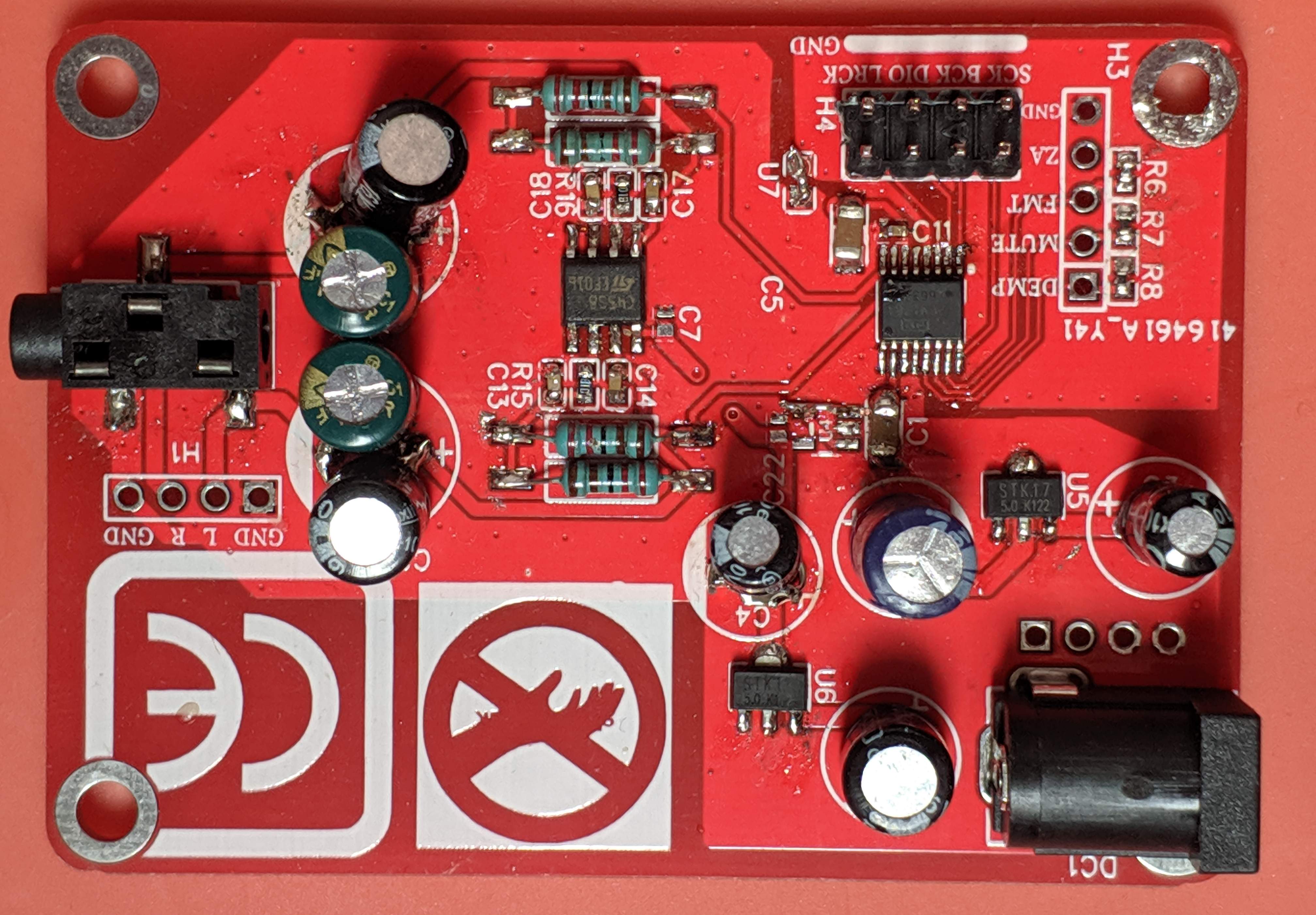
_**Output coupling capacitor**_
I also added it randomly. I adjusted it according to the impedance of the output connection. As for the type, I used electrolyte here because it is cheap.
_**Three op amps**_
The op amps in the picture are very expensive and unnecessary. The OPA337 is a Bufer. As you can see from the actual picture, I just flew the wires to it without installing any parts. The other two op amps are used for filtering. The original design is a rail-to-rail OPA, but as long as it can be powered by 12V, it can be used casually. It is an audio thing anyway. I seem to be using a 4558.


 京公网安备 11010802033920号

 GB12864BSGAANDB-V01


