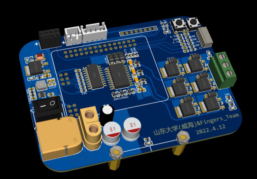
## The brushless drive module of the 17th Extreme Speed Off-Road Group, I am eager for the boss to point out the problems.
> Mainly, there is little communication in daily life. I hope to get everyone’s opinions and suggestions and will improve it in the next step.
> The [Open Editor] button in the upper right corner can directly open the entire project, including schematics and pcbs
> ###### Because it is a new version of EDA, please see the opening method in the video below
### Question
1. Burn MOS, There are 5 or 6 short circuits. Sometimes it will burn when the switch is pressed again to power up. Sometimes it will burn after a run and then power on. I have also burned out the gate driver chip twice. It should be the gate driver part. They both burned out when powering on. . . Will generate heat
2. The 5v part has been burned once (compared to the 9 times it has been burned before and after)
3. After a rough look at the waveform, there are many burrs and the peaks of the burrs are also very large
#### Thank you all in advance! ! !
-----
### Supplementary questions
1. Applied to sensorless brushless, software six-step commutation, power supply 12 and 16v have been used, in most cases 16 is very easy to burn
2. Brushless with around 4000kv The instantaneous starting current of the motor is above 10, as measured in the previous video.
3. This is also my first time using a brushless driver, and I don’t know how to improve it further. I don’t know much about four-layer boards. I drew four-layer boards mainly for the convenience of wiring and no other special purpose. If I continue to do it in the future, I will start over from the beginning based on the improvement suggestions. I hope that the entire circuit system will be more stable and will not burn again.
-----
### It is currently known that
1. The line driving the gate is too long and should be close to the MOS. It is best to stabilize the driving chip.
2. All diodes such as bootstrapping and MOS tube G-electrode discharge are Schottky, which has a short reverse recovery time.
3. The large capacitor is close to the MOS and has a higher withstand voltage.
4. The MOS copper area can be larger.
5. Software driver: Frequency adjustment

