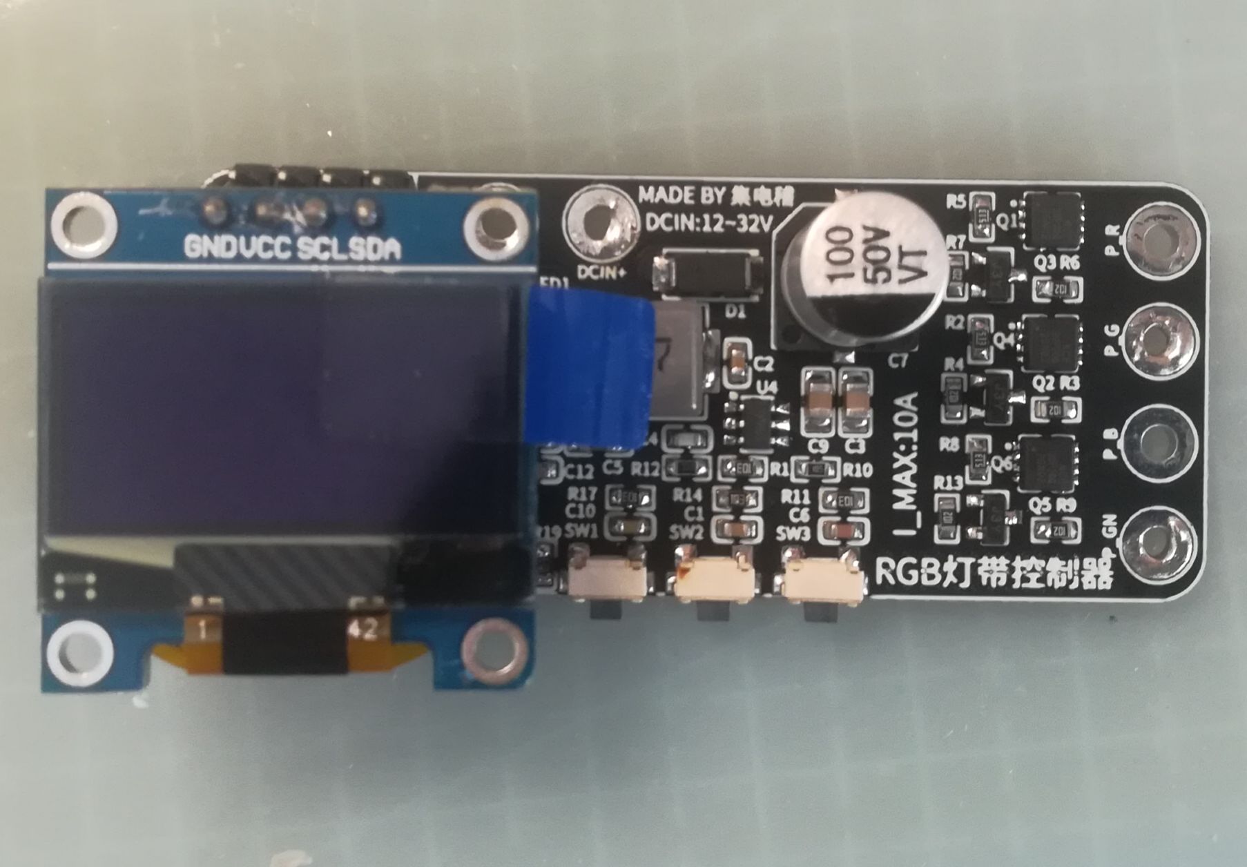
###### Written in front:
I originally wanted to make a light strip controller, but after I finished it, I found that most of the light strips have a common anode: (
So, you can start making it after you read the information clearly!
# Production Process:
## 1. Material preparation:
ESP8266 module: Everyone has this, so I don’t need to tell you where to buy it ( ̄▽ ̄)"
12864OLED screen: This is pretty easy to find, so I won’t say more ( ̄ ▽ ̄)"
PMOS tube: [NCE30P20Q](https://item.taobao.com/item.htm?spm=a21n57.1.0.0.2826523cpJtAh2&id=660710351687&ns=1&abbucket=0#detail)
(If you think it is expensive, you can use what you already have on hand. PMOS replacement with the same package, pay attention to the parameters, withstand voltage of at least 30V)
Buck chip: [ME3116](https://item.taobao.com/item.htm?spm=a21n57.1.0.0.1420523cLGG9vp&id=709191944305&ns=1&abbucket= 0#detail)
Buck inductor: [4.7UH 0630](https://detail.tmall.com/item.htm?abbucket=0&id=610264910272&ns=1&skuId=4287669464297&spm=a21n57.1.0.0.fecd523c1Ja9si)
NPN transistor: [ SS8050](https://item.taobao.com/item.htm?spm=a1z10.3-c.w4002-17890096034.10.5bbb3600zeTTyl&id=10190156502)
SMD aluminum electrolytic capacitor: [35V220UF](https://item.taobao .com/item.htm?spm=a1z10.3-c.w4002-17890096034.11.4e753600KARUki&id=39611825172)
The rest of the chip resistors and capacitors are all in 0603 package
## 2. Make the board
slightly
## 3. Solder
all the original parts on the circuit board On the same side of the board, it is recommended to use Teppanyaki welding. After welding the original patch, weld the original plug
## 4 for burning.
There is a burning interface reserved on the upper left side of the board, and you can use the USB to serial port module for burning. Note that the power supply voltage is 3.3V)
The rest is left to everyone to play freely. Goodbye!

