1. Project Introduction
This project is a training project for the JLCPCB Desktop Temperature and Humidity Meter Training Camp. It is a palm-sized desktop mini temperature and humidity meter. It uses the Sensory SHT40 as the temperature and humidity sensor, which features small size, high accuracy, and fast speed. After fully learning and understanding the training project, only the Sensory SHT40 sensor module was retained, and the following modifications were made:
1. The main controller was replaced with the inexpensive but resource-sufficient Heyu AIR001.
2. Since there is no requirement for the main frequency stability, the external crystal oscillator was removed. 3.
All surface-mount resistors and capacitors were replaced with 0603 packages to reduce the size.
4. Other components with the same function but lower price (such as shift registers, digital tubes, etc.) were replaced.
In addition, this project also added functions such as simultaneous display of dual digital tubes, sensor module disconnection detection, and entering low power mode when there is no operation.
2. Hardware
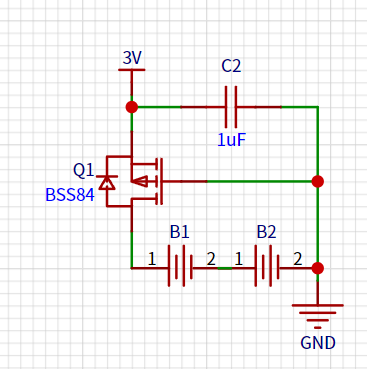
The power supply is mainly composed of two AA 1.5V dry batteries. First, a MOSFET was added at the power input to prevent reverse connection. Then, capacitors were added to each IC power supply pin to make the power supply more stable.
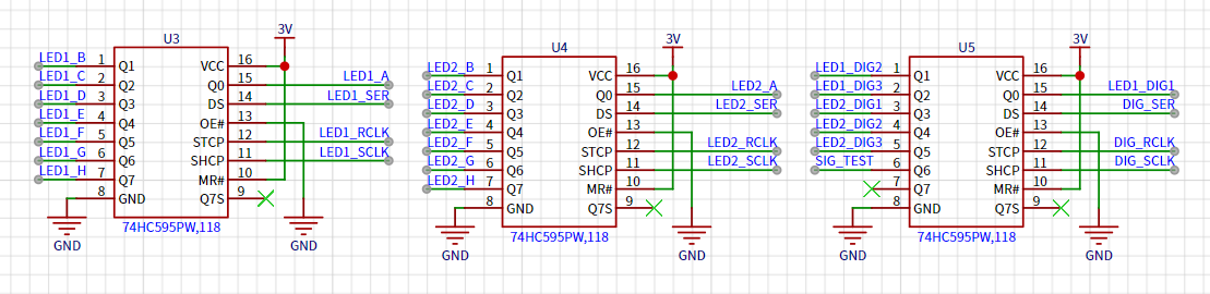
temperature and humidity sensor module is connected to the main control I2C pin via a 4-pin 1.27mm header, with pull-up resistors added according to timing requirements. After data acquisition, the data is transmitted via three shift registers to the segment and digit selection pins of two 3-digit LED displays, controlling the on/off state of each segment.
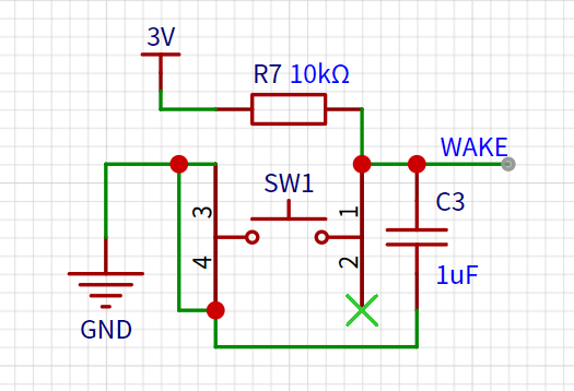
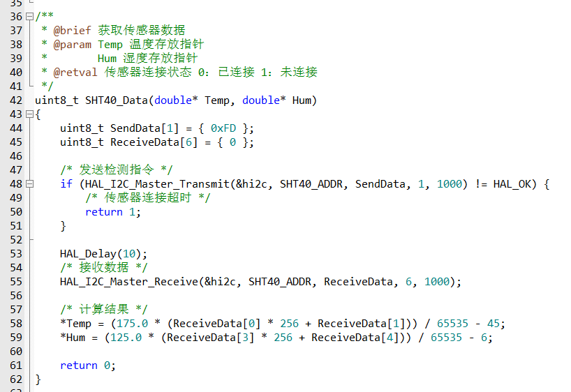
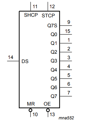
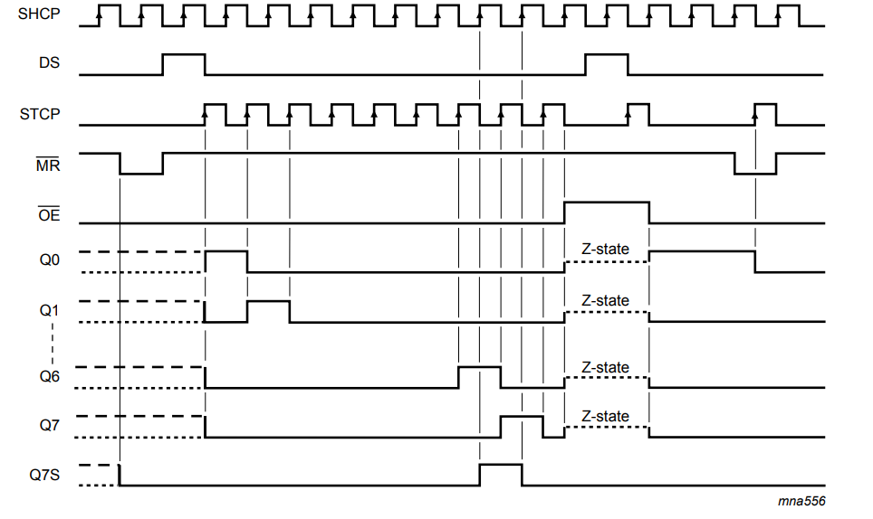
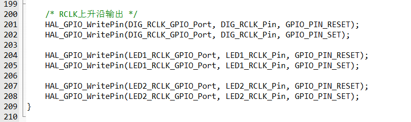
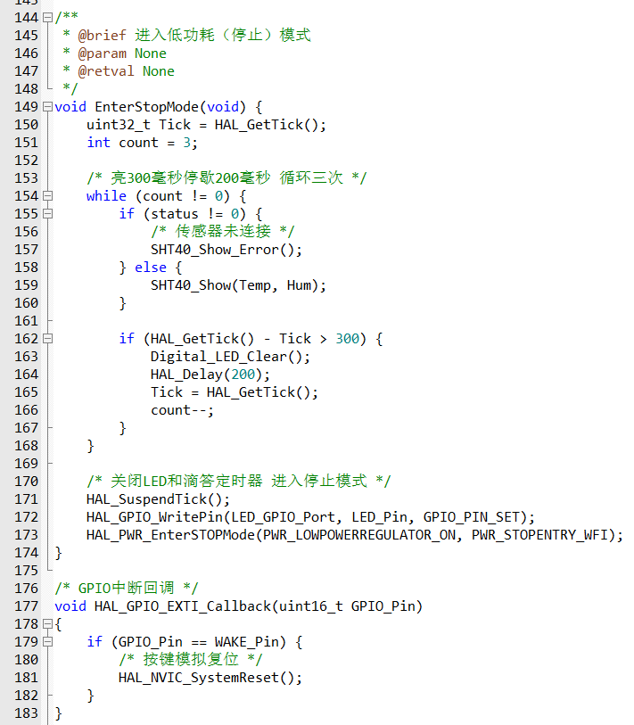
Two LEDs are used for status control to indicate whether the detector is running and whether the shift registers are functioning correctly. A button is added to start temperature and humidity sampling and wake up the system in low-power mode. The core software process is written in Keil 5 and uses the peripheral library provided by Heyu to control the on-chip peripherals. The main program logic is as follows: Upon program startup, all peripherals are initialized, the system clock is configured, and then the GPIO and function multiplexing of the LEDs, button, and I2C are initialized. Once preparation is complete, the temperature and humidity sensor can be started for data acquisition, and the LED display is controlled via the shift registers. During data acquisition, the temperature and humidity sensor performs timeout detection; if the specified response time is exceeded, a specific indicator will be displayed as shown in Video 2. After a 10-second wait, the program enters low-power mode to conserve power. Data acquisition: According to the SHT40 datasheet, its I2C address is 0x44. After the main controller sends a 0xFD acquisition command to the sensor, it returns 6 bytes of data. The 0th and 1st bytes are temperature data, and the 3rd and 4th bytes are humidity data. The actual result is then calculated according to a given formula. Data output: Sampled data is output to the digital tube via a shift register. First, let's look at the digital tube interface definition: The digital tube has 8 bit input terminals connected to 3 common connection terminals. The input terminals control the segment selection of the digital tube, and the common terminals control the bit selection. Since there are as many as 8*3*2=48 control ports, connecting them all to the main controller's GPIO ports would be a waste of IO resources. Therefore, a shift register is needed for store-and-forward. Let's look at the shift register: The shift register provides clock signals for data shifting and output through two clock control terminals. Every 8 clock cycles, 1 byte of data can be obtained through the data transmission terminal and output simultaneously bit by bit from the 8 ports. The main controller provides clock control and data transmission signals connected to three shift registers. The output ports of these shift registers are connected to two seven-segment displays. Here, data encoding is required: each segment of the seven-segment displays is encoded clockwise, prioritizing the most significant bit. The segment to be displayed is 1, and vice versa, it's 0. To provide a visual effect, the running lights surrounding the seven-segment displays are also encoded. In the original project design, displaying data separately on the two seven-segment displays didn't look very good. Since the bit selection of both seven-segment displays can be controlled simultaneously, having both displays output the same bit of data at the same time improves the display effect and reduces waiting time. The acquired data can then be used to control the display of the seven-segment displays via the shift registers: in low-power mode , if no operation is performed within 10 seconds, all peripheral clocks will be turned off, entering low-power mode. When a key input is detected, an interrupt is triggered to reset the system, allowing sampling and output to resume.
Voltage and current meters based on the CW32 development board.
1. Project Introduction
This project is a training project for the CW32 digital voltmeter and ammeter training camp. After fully understanding the training project, the following modifications were made:
The LDO circuit was removed, and the onboard USB power supply was used directly.
The digital tube was replaced with a TFT display screen for better display effects.
All surface-mount resistors and capacitors were replaced with 0603 packages to reduce size.
2. Hardware Design
The project requires the use of a development board, so only the external application circuit needs to be designed separately, and then connected to the development board via pin headers as an expansion board.
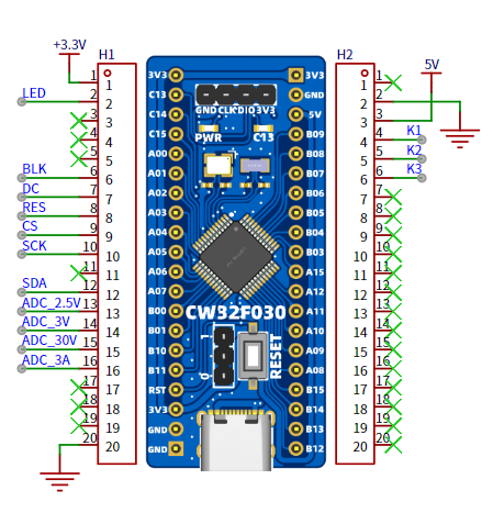
2.1 Power Supply Design
Since there is no DC power supply and considering the compact size of the expansion board, the external LDO circuit was removed, and the USB input of the development board was used directly as the power supply.

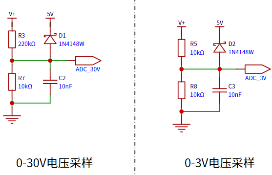
2.2 Voltage Sampling
: The voltage is input to the ADC of the core board using a dual-range sampling method. When using the ADC's internal 1.5V reference voltage, R5 (10kΩ) and R8 (10kΩ) can measure voltages between 0-3V through a voltage divider, while the voltage divider circuit composed of R3 (220kΩ) and R7 (10kΩ) can measure voltages between 0-34.5V.
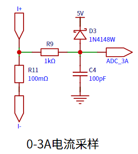
2.3 Current Sampling: Current
sampling uses a 100mΩ sampling resistor. Based on the 3A design range, its power requirement is at least 900mW.
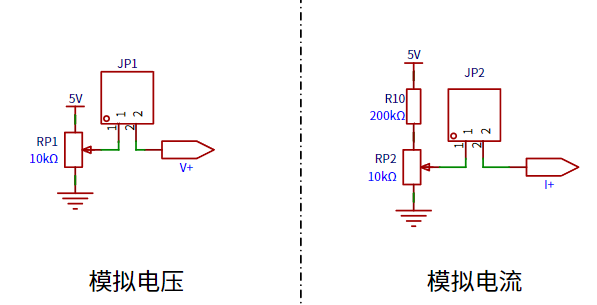
2.4 Analog Input:
For convenient functional testing, the voltage and current are directly controlled from the power supply through two potentiometers, connected to the sampling circuit using jumper caps.
2.5 Display Output:
The output section has been modified to output measured values on a TFT display screen, which is far superior to a digital tube in both price and display effect.
3. Software Design:
The system is written in Keil 5 and uses the peripheral library provided by CW32 to control various aspects of the development board. The overall process is simple: the system clock, LEDs, buttons, screen, and voltage/current acquisition functions are initialized sequentially, and then measurements are performed and output in an infinite loop.

3.1 Clock Initialization
: An external 8MHz clock is connected to a PLL to output 64MHz via 8x multiplication to the system clock, and a tick timer is initialized.

3.2 LED and Button Initialization:
LEDs and buttons can be directly controlled via GPIO, so they are initialized together.

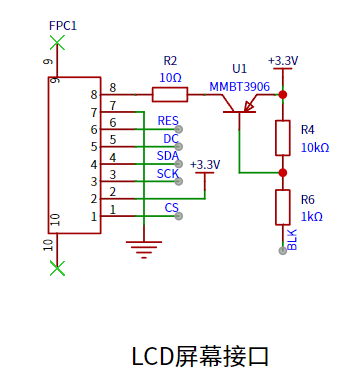
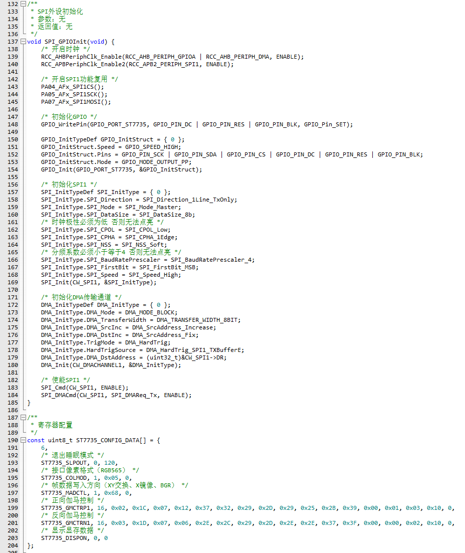
3.3 Screen Initialization:
In addition to initializing GPIO, the screen also requires configuration of SPI, DMA peripherals, and the screen's own registers.

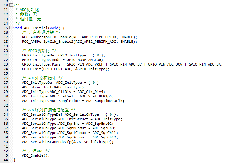
3.4 ADC Initialization:
The ADC mainly uses a multi-channel sequential scan mode to measure the 0-3V voltage range, 0-30V voltage range, and 0-3A current range channels sequentially.
3.5 Voltage and Current Measurement:
A mean filtering algorithm is used for voltage and current measurements to smooth the results. Multiple ADC values are sampled continuously using a circular queue, and the average value is taken. The actual value is then calculated using a voltage divider circuit.


3.5 Display Output:
For the characters to be displayed, first take the modulus, then fill in the font color and background color, and finally convert it into RGB565 data format and send it to the screen.


Voltage and current measurement.mp4
CW32_Based_Voltage_Ammeter.zip
PDF_Voltage and Current Meter Based on CW32 Development Board.zip
Altium_Voltage and Current Meter Based on CW32 Development Board.zip
PADS_Voltage and Current Meter Based on CW32 Development Board.zip
90610
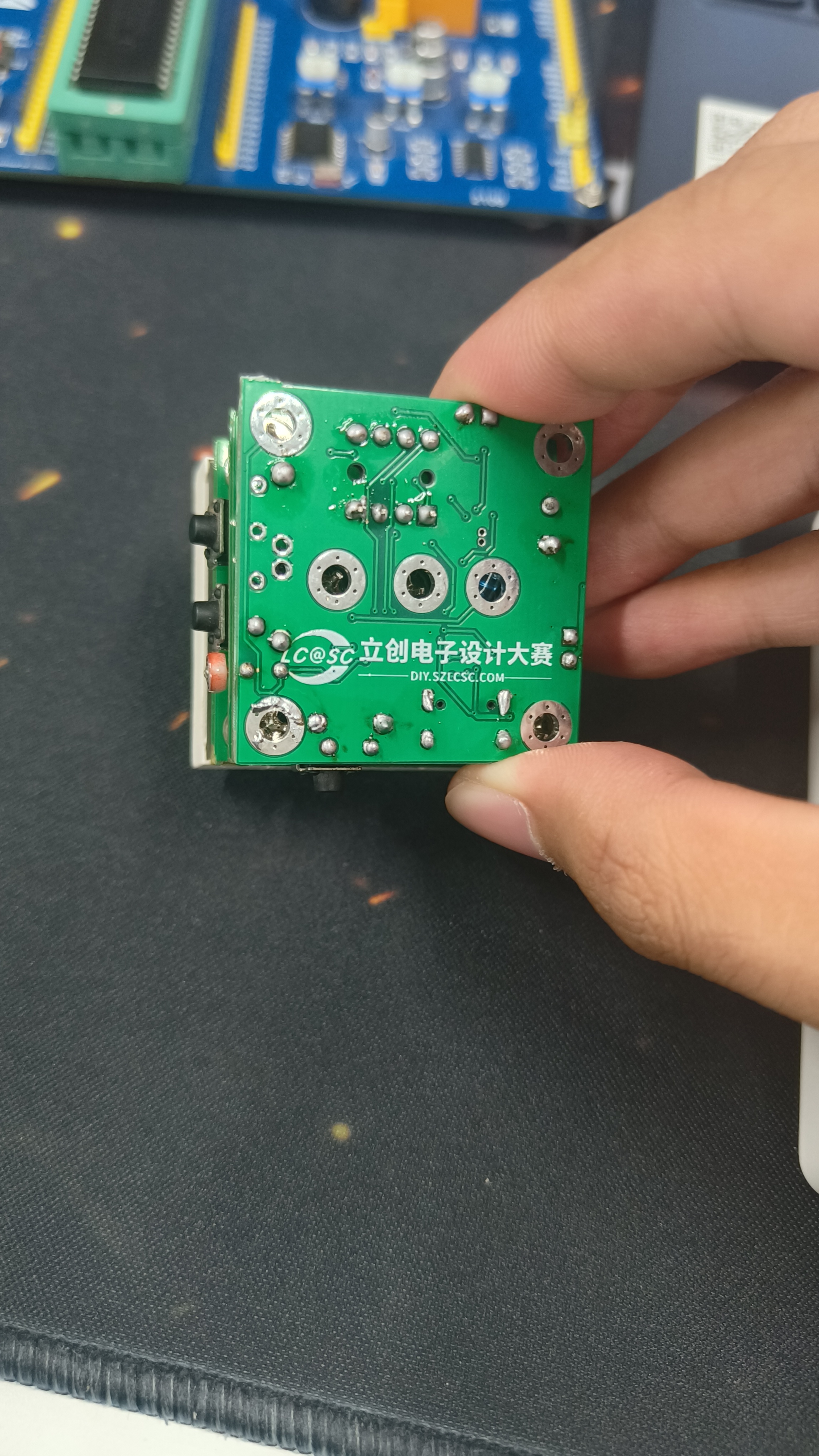
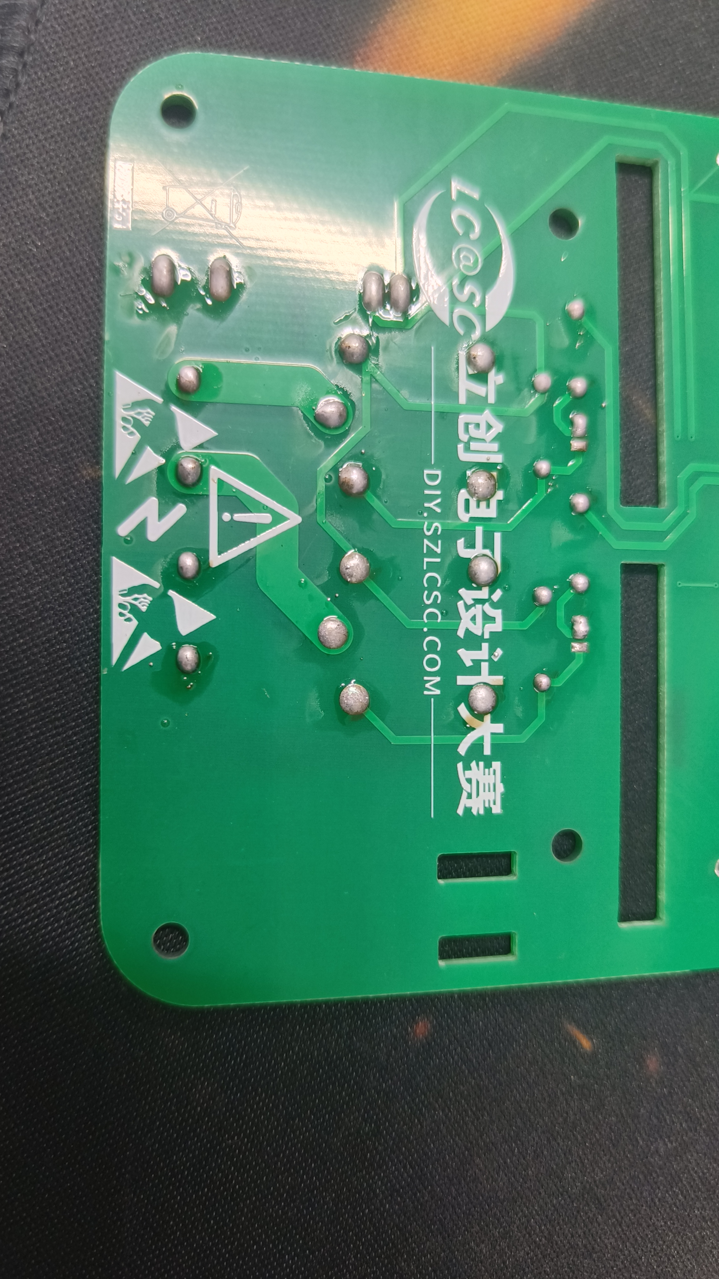
#8th LCSC Electronics Design Contest# Dot Matrix Reminder Water Dispenser
The interval reminder function is implemented using the STC8H1K08 chip and 74HC595 driver dot matrix.
Note: * Required fields,
please fill them in during the registration phase ↓
* 1. Project Function Introduction
The DIY Water Reminder is a smart device based on the STC8H1K, designed to help people maintain good hydration habits. This device can remind users to drink water at set times to ensure they stay adequately hydrated, contributing to health and quality of life.
Timed Water Reminders: The DIY Water Reminder can be set to remind users at set times, such as once per hour. This helps users avoid forgetting to drink water due to being busy.
Display Screen: The device has a dot-matrix display screen that shows the current time, reminder schedule, and water level in the cup. Users can easily understand the information.
Sound Reminders: In addition to the dot-matrix display, the device is also equipped with a buzzer reminder function.
Customizable Reminders: Users can customize the reminder frequency and time according to their needs. This customization function allows the device to adapt to different people's lifestyles.
*2. Project attributes
have only been publicly disclosed on the LCSC EDA open-source platform; Original.
* 3. Open source license
GPL3.0.
Please fill in the details during the competition stage.
* 4. Hardware:
Use M3*10mm double through studs to connect the top and bottom plates. Note the soldering method between the DS1302 battery holder and the DS1302. Changing the time requires re-downloading the program. After changing the time, comment out the time-writing code and download again. Please use a passive buzzer (the sound is music - Two Tigers). If board assembly prevents board production, please delete the oval border layer in the middle of the PCB and cut it open yourself.

* 5. Software:
See the attachment for the specific source code. Open the source code in Keil and use STC-ISP to download the program to the STC8H1K chip.
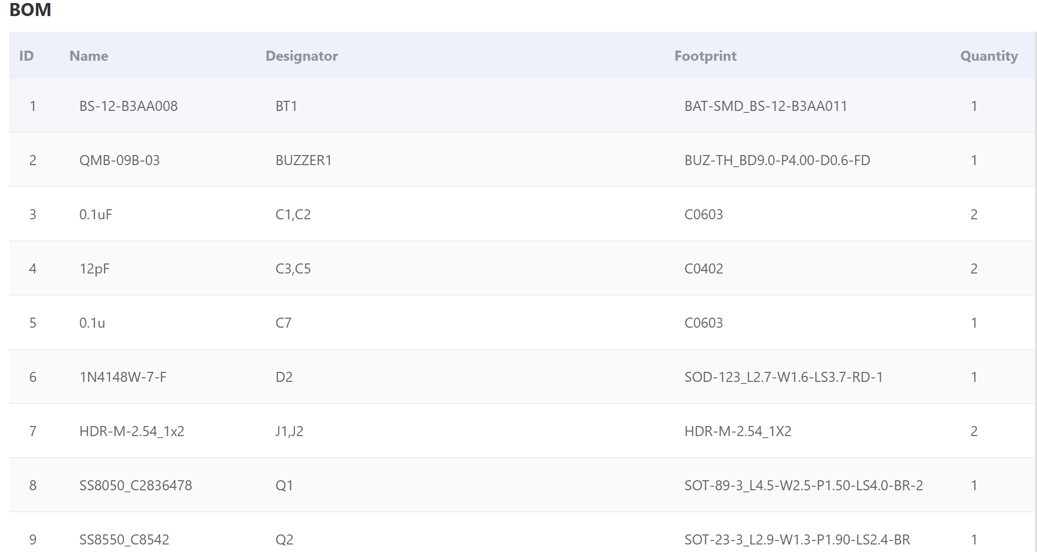
* 6. BOM list.
* 7. Competition logo verification.

* 8. Demo your project and record a video to upload.
BOM_Dot Matrix Reminder Water Dispenser (Verified).xlsx
PCB.pdf
Schematic diagram.pdf
source code.zip
90611
Dot matrix water dispenser with reminder function (verified)
The interval reminder function is implemented using the STC8H1K08 chip and 74HC595 driver dot matrix.
Connect the top and bottom plates using M3*10mm double studs. Note the soldering method between the DS1302 battery holder and the DS1302. Changing the time requires re-downloading the program. After changing the time, comment out the time code and download again. Please use a passive buzzer (the sound should be music - Two Tigers). If you cannot produce a PCB due to panelization issues, please delete the oval frame layer in the middle of the PCB and cut it open yourself.
Two Tigers.zip
BOM_Dot Matrix Reminder Water Dispenser (Verified).xlsx
90612
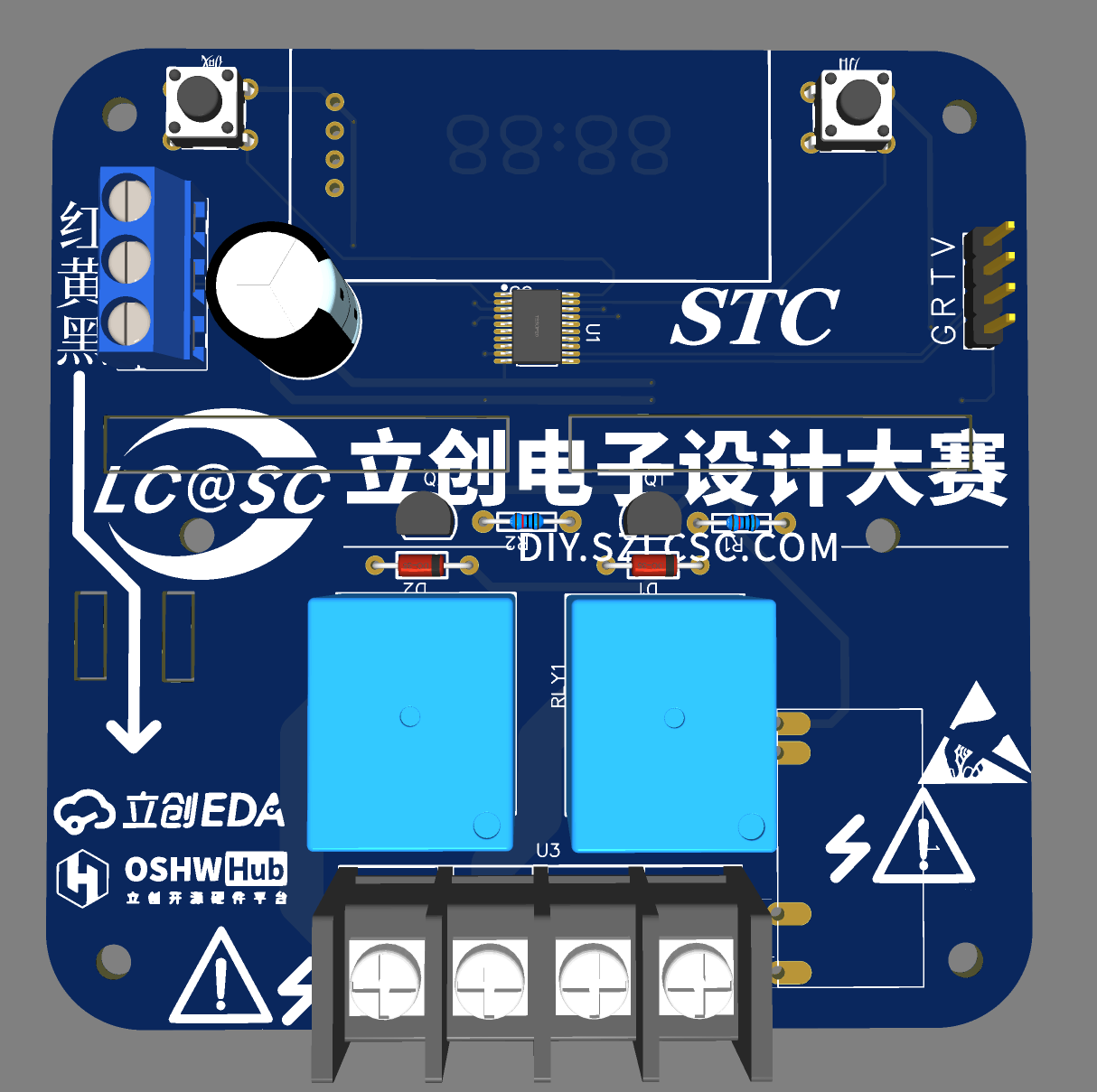
#8th LCSC Electronics Design Contest# STC8H Temperature Controller
A temperature control switch implemented using an STC8H1K08 microcontroller and a DS18B20.
Note: * Required fields,
please fill them in during the registration phase ↓
* 1. Project Function Introduction
This project aims to monitor and maintain the temperature of specific environments. It can be applied to various fields such as greenhouses, incubators, heaters, and refrigeration equipment to ensure that the temperature remains stable within the required range.
Project Functions:
Temperature Monitoring: Real-time monitoring of ambient temperature via connection to a temperature sensor (e.g., DS18B20).
Temperature Setting: Users can set the desired target temperature so that the controller can adjust the temperature according to the set value.
Digital Display: The device is equipped with a digital display screen to display information such as the current temperature and target temperature.
Temperature Calibration: Features a calibration function to ensure accurate temperature measurements.
*2. Project attributes
have only been publicly disclosed on the LCSC open-source platform.
* 3. Open-source license
GPL3.0
: Please fill in during the competition stage. ↓
*4. Hardware
temperature data is stored in the EEPROM and is not lost upon power failure
. (Note: To achieve negative temperatures, the EEPROM reads 64 as 0 degrees Celsius, meaning this controller supports control from -63 to 192 degrees Celsius (but in reality, the DS18B20 only supports -55 to 125 degrees Celsius).
The default program is to turn on the controlled device, causing a temperature drop (refrigerator). A reverse version (thermos) will be uploaded later.)


*5. Software: The source code
is normally burned using STCISP software; see attachment. * 6. BOM list: See attachment. Note the pin positions of the purchased AC-DC module. The DC+ and DC- pins on the one I bought were reversed compared to the schematic. I used the axial lead of a resistor to move it to the corresponding position, but this is still a significant safety hazard. * 7. Competition LOGO verification .* 8. Demonstrate your project and record a video for upload. Video requirements: Please shoot in landscape mode, with a resolution of at least 1280×720, in Mp4/Mov format, and a maximum file size of 100MB per video; Video title: LCSC Electronics Competition: {Project Name} - {Video Module Name}; e.g., LCSC Electronics Competition: "Autonomous Driving" - Team Introduction. More details: https://diy.szlcsc.com/posts/15a52db9fd7d40c492eb505280278e45
pcb.pdf
Schematic diagram.pdf
BOM_STC8H Temperature Controller - Verified.xlsx
Refrigerator type.hex
main.zip
90613
Uno controlled PTC constant temperature heating table
The Arduino Uno is used to control a bidirectional thyristor, and zero-crossing detection and successive approximation methods are employed to achieve constant temperature control.
Preface :
I bought a 140W PTC heating platform from Deer Fairy, but it lacks temperature display and adjustment functions. Luckily, I had a spare Uno and a 1.3-inch OLED screen that I mistakenly bought when making an electronic load, so I decided to use them.
Warning: This project involves 220V AC power. The creator must have some basic circuit knowledge. The author guarantees the safety of the circuit design but is not responsible for any safety issues arising during the creation and use of the circuit!
1. Software Function Introduction and Design Ideas : The software
is compiled using Arduino IDE. A rotary encoder adjusts the set temperature. Double-clicking the encoder's SW key saves the set temperature to the Uno's EEPROM. Holding down the SW key for 3 seconds starts heating. During heating, the third line of the screen displays "Heating," and there is no display when not heating. Initially, I wanted to use Arduino's library function PID control, but later found that it couldn't control the temperature because the PID period is 2ms, while the sinusoidal AC current period is 20ms. Considering that PTC temperature control doesn't require extreme precision, and given the non-linear characteristics of PTC heating, an approximation method was used. After bridge rectification, the zero-crossing signal is sampled every 10ms. After 10 samples (100ms), if the current temperature is 40 degrees lower than the set temperature, the PWM remains high.
The hardware
design considers the separation of strong and weak current circuits, and the PCB is designed as three boards: a zero-crossing detection and SCR control board, an encoder adjustment and OLED display board, and an UNO adapter board. The PCB design is very amateurish; I don't know how to lay copper on 220V lines, so areas near 220V lines are left unpainted. To save money, the three boards were drawn as a single board frame. It's said that JLCPCB charges for panelized boards if the slot length exceeds 75%, but during my board production, it was approved as a single board – a matter of luck.
Ignore the unconnected jumper wires. After cutting the board, connect them with cables.
3. Attachments
4. Some individual components are available via Taobao links
: 1. 3OLED https://item.taobao.com/item.htm?spm=a21n57.1.0.0.2790523cEgrK2L&id=37848651711&ns=1&abbucket=7#detail
The encoder module pin headers need to be removed and soldered in reverse. https://item.taobao.com/item.htm?spm=a1z09.2.0.0.288f2e8dAfPp8P&id=648231745636&_u=f2h4vops881c
Connector 2.54 Glue housing straight pin header https://item.taobao.com/item.htm?spm=a1z09.2.0.0.288f2e8dAfPp8P&id=526112254730&_u=f2h4vops1065
You can buy both the 2-pin and 4-pin cables from the same store. The FC-10P cable is 20cm long, and the DC3-10P cable is also available; search for both from the same store.
5. Assembly Precautions:
Don't throw away the PTC heating platform screws that come with the Deer Fairy product; they are heat-insulating and quite useful. After countersunk the original four holes on the PTC board, use 3x50mm screws to pass through and secure them with nuts. Then, fit the screws onto the PTC heating platform screws that come with the Deer Fairy product. It tested for 20 minutes without any problems; the 3D printed shell (PLA material) can withstand the load. Instructions are included in the attachment.
BOM_ptc constant temperature soldering station.csv
Gerber_PCB_pct Thermostatic Soldering Station.zip
Assembly PTC images.rar
software.rar
90615
[Allwinner Online x YuzukiHD] Nezha D1s Development Board
[Allwinner Online & YuzukiHD Collaboration] Based on Allwinner D1s chip design, mainly used for D1s performance evaluation, solution research, developer DIY, etc.
D1s Introduction:
The D1s is a high-performance, cost-effective AIoT chip launched by Allwinner for the smart decoding market. It uses the Alibaba Pingtouge C906 processor with a 64-bit RISC-V architecture, has 64MB of built-in DDR2 memory, supports Linux systems, and integrates a large number of self-developed audio and video codec IPs. It supports full-format video decoding including H.265, H.264, MPEG-1/2/4, and JPEG, and supports multiple audio interfaces such as ADC, DAC, I2S, PCM, DMIC, and OWA. It can be widely used in smart home panels, smart commercial displays, industrial control, and automotive products.
Function Introduction:
The Nezha D1s development board is a solution evaluation board based on the Allwinner D1s chip design.
Supports RGB display interface;
supports DSI interface;
supports TP interface;
supports LINEIN interface; supports HPOUT interface;
supports TVIN/TVOUT interface;
integrates Allwinner XR829 WiFi/BT chip;
supports JATG/UART debug;
supports SD card;
supports USB Host/Device;
can be used for chip evaluation, solution research and personal DIY, and can be applied to product forms such as game consoles, smart commercial displays, and smart central control. Strengths: Screen display, video decoding
system block diagram .

Related materials
: D1s online documentation: https://d1s.docs.aw-ol.com/
SDK download method: https://d1s.docs.aw-ol.com/study/study_2getsdk/
Information updates and material summary post: https://bbs.aw-ol.com/topic/1257/
Purchase address: Taobao purchase link:
https://item.taobao.com/item.htm?id=672608097923
Related images
: Video
decoding 1080p@60 video, and audio playback using a Bluetooth speaker (screen size 480 * 272, maximum supported 1920 * 1080 screen) (green board is the previous test version)
20220418234113.mp4
PDF_【Allwinner Online x YuzukiHD】Nezha D1s Development Board.zip
Altium_【Allwinner Online x YuzukiHD】Nezha D1s Development Board.zip
PADS_【Allwinner Online x YuzukiHD】Nezha D1s Development Board.zip
BOM_【Allwinner Online x YuzukiHD】Nezha D1s Development Board.xlsx
90616
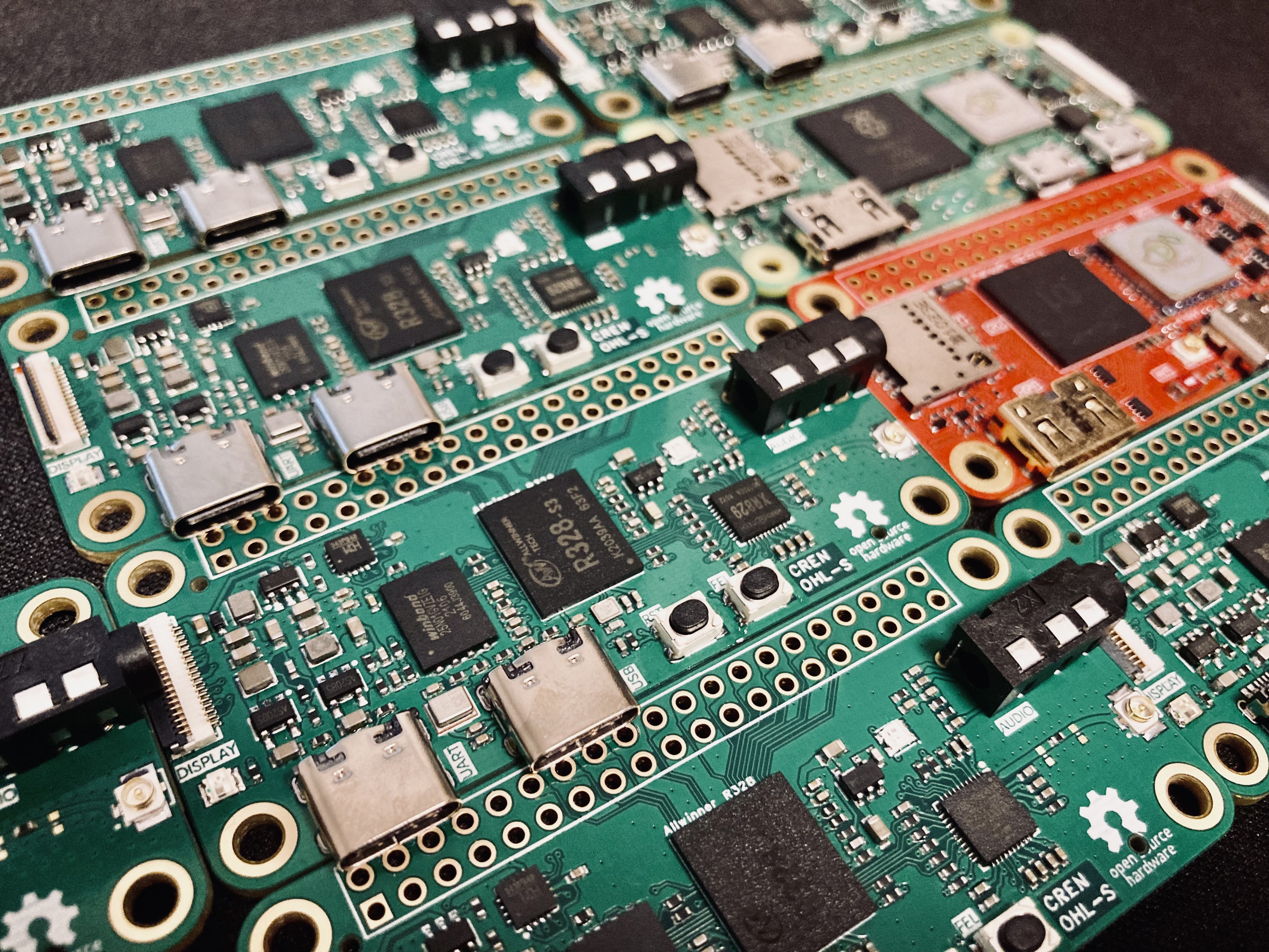
Yuzuki Rosetta Low-Cost Linux Development Board
The Yuzuki Rosetta is a low-cost Linux development board based on the Allwinner R328-S3. It offers dual-core A7 processors, 128MB of memory, NAND Flash, Wi-Fi & BitTorrent, and a rough estimated cost of 35 yuan.
The Yuzuki Rosetta
is a low-cost Linux development board based on the R328-S3 chip. It features dual-core A7 processors, 128MB of RAM, NAND Flash, Wi-Fi & BT
Cortex A7 * 2
DDR3 128MB
XR829 Wi-Fi, BT
MEMS
Audio Codec & 3.5mm
RGB LED, WS2812
CH343P UART to USB
SPI, and an 18-pin TFT LCD

. The manual is available at: https://github.com/YuzukiHD/YuzukiRosetta.
The R328-S3 chip was widely disassembled and costs approximately 4 RMB per chip (some used chips may have burned-out eFuse fuses, so purchase with caution). Therefore, this chip was chosen to build this development board. The rough estimated cost is 35 RMB (however, the gold plating here will definitely cost more than 35 RMB).
[Image attached]
PDF_Yuzuki Rosetta Low-Cost Linux Development Board.zip
Altium_Yuzuki Rosetta Low-Cost Linux Development Board.zip
PADS_Yuzuki Rosetta Low-Cost Linux Development Board.zip
BOM_Yuzuki Rosetta Low-Cost Linux Development Board.xlsx
90617
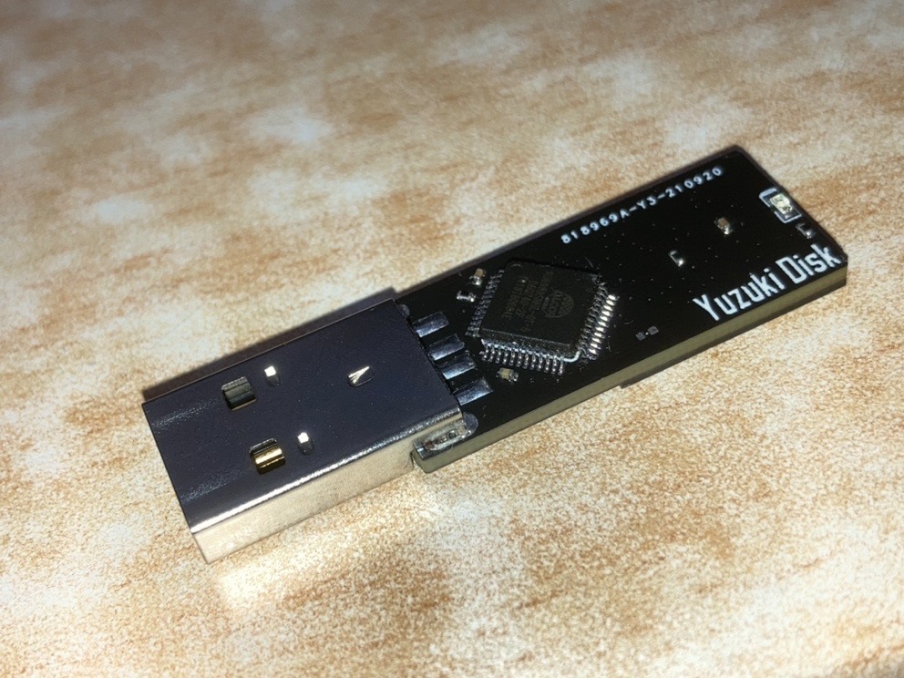
Alcor AU6989 USB 2.0 flash drive (Anguo)
The Alcor AU6989 USB flash drive solution verification board uses an Alcor controller and supports BGA132, BGA152, and BGA136 packaged NAND flash memory chips, supporting SLC/MLC/TLC/QLC.
After completing the verification,
I tried designing a USB flash drive board as a practice

project for a four-layer board. The background
was a chemistry class during a winter day in my senior year of high school. Looking at the blackboard full of writing, I was dozing off, so I secretly took out my phone and opened Taobao to see what interesting things I could find.
Suddenly, my eyes lit up: Lao Wang's new CBM2098S USB flash drive controller board, only 0.5 yuan each! I was overjoyed, thinking that making some USB flash drives myself would be a lot of fun. My balance dropped by 55 yuan. The
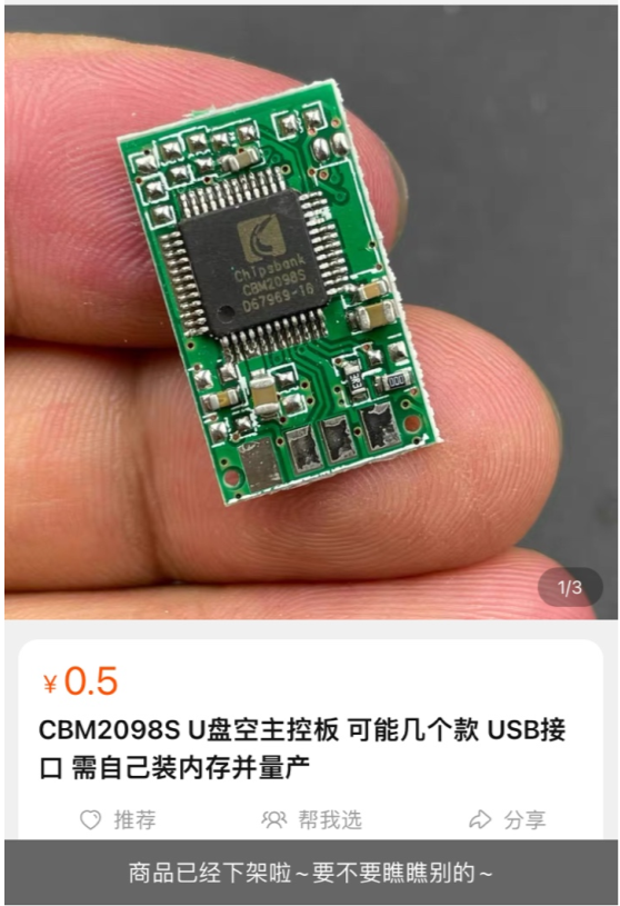
board arrived, and upon opening the package, I felt a wave of disappointment. It was just a TSOP48 flash memory socket. Besides the CBM2098S, there was another controller: AU6989SNHL-GT.
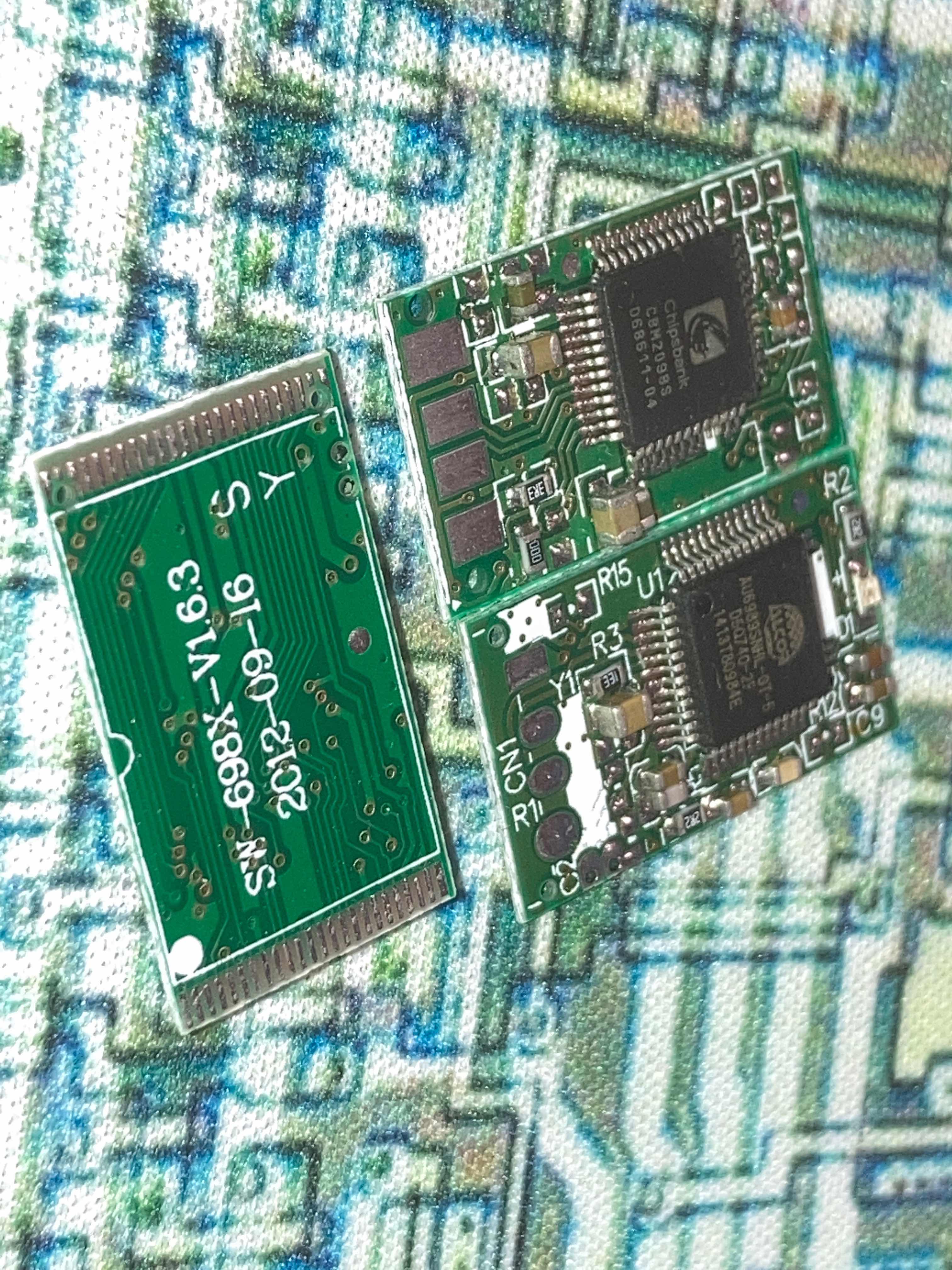
Nowadays, BGA flash memory chips are more common, and this TSOP48 was a real problem. TSOP48s are also quite difficult to solder. I salvaged a flash memory from an old set-top box and made a 128MB USB flash drive. With the college entrance exam approaching, I lost interest in it.
After the college entrance exam, I stumbled upon the LCEDA software. I tried it out on some simple boards and found it very useful, giving this hopeful
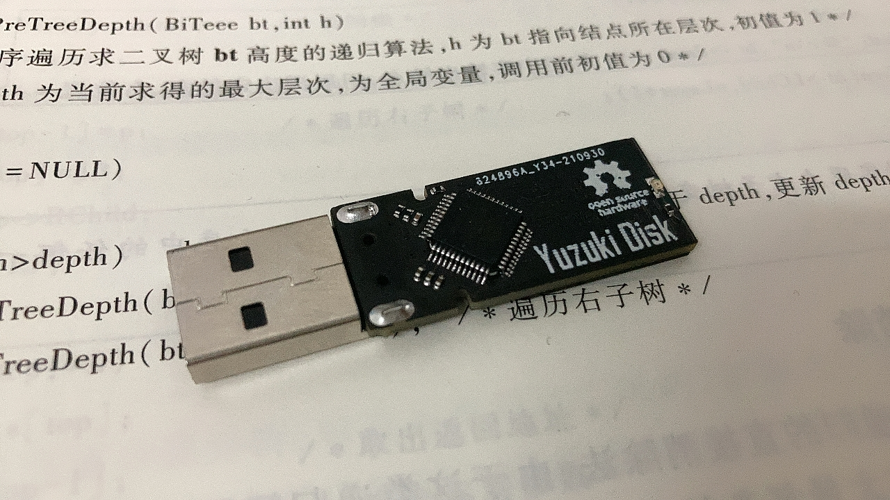
but hopeless user, who had downloaded and deleted AD three times, a glimmer of hope. On July 1st, JLCPCB provided a free 4-layer board prototype. I knew it was time to fulfill my unfulfilled wish, so I worked through the night to design the circuit. After several revisions and prototype tests, I finally had a usable main control board.
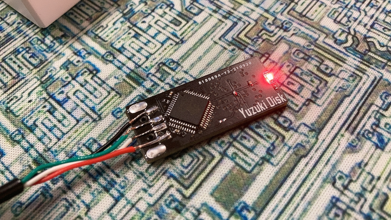
Project Overview:
A USB flash drive main control board (PCBA) based on the Alcor AU6989, with a minimal design, minimal external circuitry, and support for VCCQ 3V3 flash memory.
Support for the main controller
requires soldering a crystal oscillator (pins 9 and 10 are crystal oscillator pins, design your own). Are these main controllers still available? (
AU698X series ,
AU699X series
do not require a crystal oscillator
, AU6989SN-GT series
theoretically supports NAND Flash types (please refer to the firmware for a specific model support list):
BGA132 SLC/MLC/TLC/QLC
, BGA136 SLC/MLC/TLC/QLC,
BGA152 SLC/MLC/TLC/QLC,
maximum 2CH 4CE or 1CH 8CE. )
Update Log:
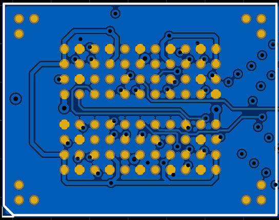
V1.4
Refactored routing, PCB layout
verification successful.
V1.3
Verification completed, successful card opening.
(My board design is terrible, got scolded, redrawing, sob sob.)
Low quality USB A connector, I love you!!!


V1.2
verification was successful, but a problem occurred
: the computer blue-screened upon power-up due to a reversed USB data cable connection (
after using a jumper cable, the drive was recognized, but the flash memory was not)
. V1.1
updated the BGA152 pads, using a simplified design
with the controller using an angled design, temporarily removing the crystal oscillator circuit
and adding support for Samsung 27nm jumpers SB1.

V1.0
completed the design, but prototype production
verification failed due to a problem.

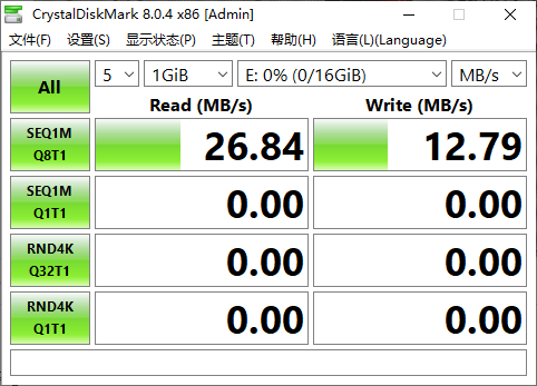
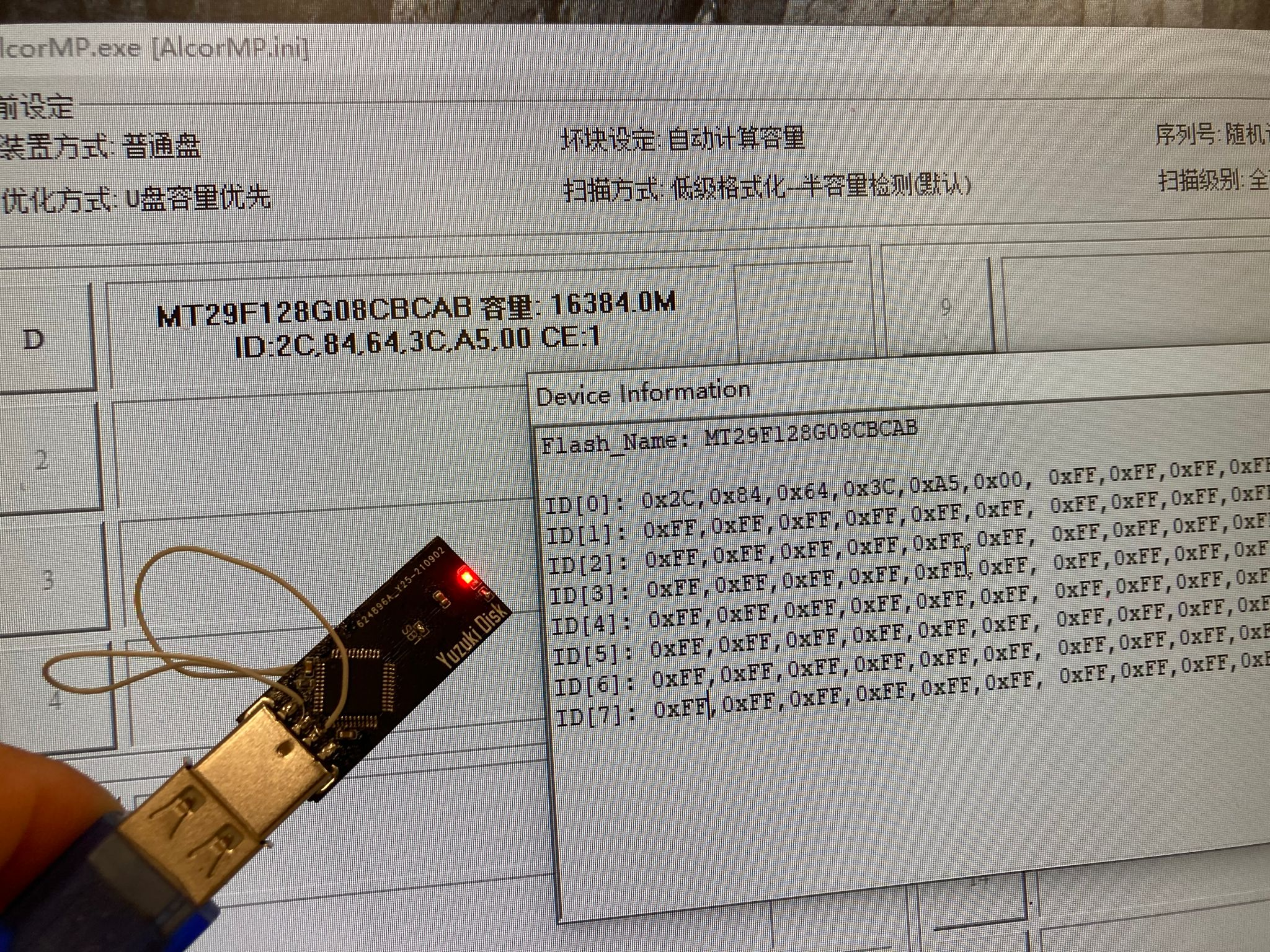
The card opening software settings for the
mass production tool version: ALCOR_U2_MP_v19.04.01.00.
The default configuration is fine; please search for the software yourself on Baidu.
BOM_Alcor AU6989 USB2.0 flash drive Anguo.xlsx
90618
electronic
 The data acquisition
 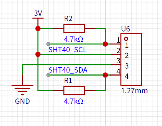 Two LEDs are used for status control to indicate whether the detector is running and whether the shift registers are functioning correctly. A button is added to start temperature and humidity sampling and wake up the system in low-power mode. The core software process is written in Keil 5 and uses the peripheral library provided by Heyu to control the on-chip peripherals. The main program logic is as follows: Upon program startup, all peripherals are initialized, the system clock is configured, and then the GPIO and function multiplexing of the LEDs, button, and I2C are initialized. Once preparation is complete, the temperature and humidity sensor can be started for data acquisition, and the LED display is controlled via the shift registers. During data acquisition, the temperature and humidity sensor performs timeout detection; if the specified response time is exceeded, a specific indicator will be displayed as shown in Video 2. After a 10-second wait, the program enters low-power mode to conserve power. Data acquisition: According to the SHT40 datasheet, its I2C address is 0x44. After the main controller sends a 0xFD acquisition command to the sensor, it returns 6 bytes of data. The 0th and 1st bytes are temperature data, and the 3rd and 4th bytes are humidity data. The actual result is then calculated according to a given formula. Data output: Sampled data is output to the digital tube via a shift register. First, let's look at the digital tube interface definition: The digital tube has 8 bit input terminals connected to 3 common connection terminals. The input terminals control the segment selection of the digital tube, and the common terminals control the bit selection. Since there are as many as 8*3*2=48 control ports, connecting them all to the main controller's GPIO ports would be a waste of IO resources. Therefore, a shift register is needed for store-and-forward. Let's look at the shift register: The shift register provides clock signals for data shifting and output through two clock control terminals. Every 8 clock cycles, 1 byte of data can be obtained through the data transmission terminal and output simultaneously bit by bit from the 8 ports. The main controller provides clock control and data transmission signals connected to three shift registers. The output ports of these shift registers are connected to two seven-segment displays. Here, data encoding is required: each segment of the seven-segment displays is encoded clockwise, prioritizing the most significant bit. The segment to be displayed is 1, and vice versa, it's 0. To provide a visual effect, the running lights surrounding the seven-segment displays are also encoded. In the original project design, displaying data separately on the two seven-segment displays didn't look very good. Since the bit selection of both seven-segment displays can be controlled simultaneously, having both displays output the same bit of data at the same time improves the display effect and reduces waiting time. The acquired data can then be used to control the display of the seven-segment displays via the shift registers: in low-power mode , if no operation is performed within 10 seconds, all peripheral clocks will be turned off, entering low-power mode. When a key input is detected, an interrupt is triggered to reset the system, allowing sampling and output to resume.
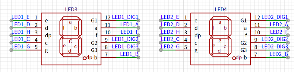


 京公网安备 11010802033920号

 M85049-33-112


