Silicon carbide totem pole 3KW power
supply input specifications: AC 110V~270V 20Amax
output specifications: DC 350V-430V 20Amax
power 3000W (design power 3500W)
efficiency 98.5%
This power supply is the pre-stage PFC stage for a subsequent 3KW LLC power supply or full-bridge adjustable power supply.
This design is described in detail, please read carefully. Criticism and corrections are welcome. Likes and favorites will be entered into a draw to receive a complete PFC totem pole board!
I. Introduction to PFC Principles
1.1 What is PFC?
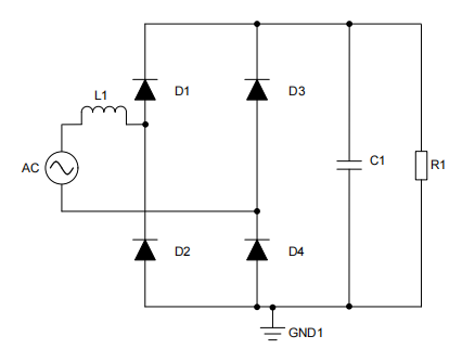
To understand PFC, we must first define power factor. Power factor is the ratio of active power to apparent power, measured in watts. Active power is the power consumed by the load, while apparent power is the power circulating between the power supply and the load. An ideal power factor is 1, meaning there is no loss due to reactive power, and all apparent power is active power. Switching power supplies are commonly used for power factor correction. Switching power supplies typically use a diode bridge to rectify alternating current (AC) signals into direct current (DC) signals. This diode bridge chops the AC signal, affecting the power factor and total harmonic distortion (THD).
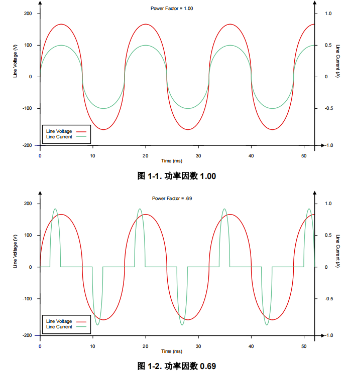
Figures 1-1 and 1-2 show the waveforms of systems with power factors of 1 and 0.69, respectively. Note that a lower power factor leads to an increase in peak current.
Switching converter topologies are used for active power factor correction to improve power efficiency and density. One of the most successful topologies over the past two decades has been a boost PFC, which uses a single low-side MOSFET, an inductor, and a diode. To achieve efficient AC/DC conversion, the MOSFET gate driver must meet specific requirements to effectively drive the MOSFET. Some of these requirements include peak drive current and switching characteristics. High drive current
is required because PFC requires high-power switching. Fast switching characteristics such as rise and fall times and propagation delay enable fast switching transitions, reducing losses and increasing efficiency. The reason for the need for fast switching transitions lies in the switching losses in the MOSFET. MOSFETs are inefficient during turn-on and turn-off due to the dynamic voltage and current they handle. Other requirements include undervoltage lockout and noise handling capabilities. Boost PFC is typically driven by a single-channel, low-side, non-isolated gate driver; the diagram below shows a boost PFC.

1.2 Why is PFC used in switching power supplies?
Relevant national regulations mandate the inclusion of PFC in electrical equipment exceeding a certain power rating to improve grid quality. Without PFC, the overall grid efficiency waveform will be affected, potentially causing other users to experience power outages. Power factor (PF) measures the degree of efficient power utilization; a higher value indicates higher power efficiency. As a capacitor-input circuit, the phase difference between current and voltage in a switching power supply leads to power loss. To reduce this loss and improve power utilization efficiency, PFC circuits are introduced into switching power supplies. PFC circuits improve the power factor of the power supply, enabling it to effectively manage reactive power while consuming active power, thereby reducing unnecessary losses on the grid and improving the overall efficiency of the power system.
1.3 What are the different types of PFC?
Compared to traditional boost PFC, interleaved boost PFC is a more efficient but more complex option. Interleaved boost PFC improves system efficiency but increases component count.
The gate driver requirements for interleaved boost systems are very similar to those for boost systems, except the second MOSFET requires an additional channel. To drive the two MOSFETs required for this topology, a dual-channel low-side gate driver, such as the UCC27624, is typically used. The figure below shows an example of an interleaved boost circuit.

Due to the development of third-generation semiconductors, totem-pole bridgeless PFC has begun to be widely adopted.

Traditional PFC converters implement passive diode bridges for rectification; this technology is now called passive PFC technology. The advantages of this type of solution are: simple design, high reliability, slow system control loop speed, and low cost. However, the disadvantages are also obvious: passive components are heavy, the power factor is low, and significant power losses occur, resulting in large heatsink size and high heat dissipation. Further investigation revealed that on low-voltage lines in wide-supply applications, the input bridge consumes approximately 2% of the input power. If designers can suppress one of the series diodes, they can save 1% of the input power, thereby increasing efficiency from 94% to 95%. Due to the aforementioned drawbacks, the rated power of traditional bridge-type PFCs is limited to below several hundred watts, especially in hybrid electric vehicles (HEVs) or electric vehicles (EVs), where small space and light weight are critical design parameters. Therefore, the trend towards bridgeless architectures is increasingly evident, which eliminates the traditional diode bridge. OBCs are based on silicon power devices and suffer from limitations such as low efficiency, low power density, and high weight. With the advantages of SiC MOSFETs, designers can take advantage of their superior performance in fast switching, low reverse recovery charge, and low RDS(ON) to greatly improve these limitations.
1.4 Why can only GaN and SiC be used for high-frequency transistors in totem-pole PFCs, and not ordinary MOS?
An inherent problem in totem-pole PFCs is the operating mode transition at the zero-crossing of the AC voltage. When the AC input transitions from the positive half-line to the negative half-line at the zero-crossing point, the duty cycle of the low-side high-frequency switch SiC2 changes from 100% to 0%, and the duty cycle of SiC1 changes from 0% to 100%. Due to the slow reverse recovery speed of the high-side diode (or the body diode of the MOSFET), the cathode voltage of D2 cannot immediately jump from ground to a positive DC voltage (which leads to a large current spike). Because of this issue, designers cannot use Si MOSFETs in a continuous conduction mode (CCM) totem-pole PFC.
Therefore, SiC1 and SiC2 must be gallium nitride (GaN) or SiC MOSFET field-effect transistors (FETs) with low reverse recovery; for this project, we chose SiC.
1.5 What is the direction of the operating current in a totem-pole PFC?

Totem-pole bridgeless PFC operation during the positive half-cycle: (A) S2 on (B) S2 off.

Totem-pole bridgeless PFC operation during the negative half-cycle: (A) S1 on (B) S1 off.
The high-frequency GaN FET operates at a switching frequency of 65kHz, and a pair of Si MOSFETs operate at the power frequency (approximately 45Hz to 60Hz). Therefore, the conduction path includes a GaN switch and a low-frequency Si switch, significantly reducing conduction losses. Dual-channel interleaving technology is used to reduce conduction losses and
input 98.5%.
1.6 What is the waveform generation logic of the totem-pole PFC (CCM), and how is the zero-crossing spike resolved?

Waveform generation logic: During the positive half-cycle of AC, the master PWM switches from a low duty cycle to a high duty cycle and then back to a low duty cycle, making the inductor current sinusoidal, while the slave switches do the opposite and complement each other. However, totem pole PFC has a zero-crossing inductor current commutation spike problem. In order to improve the current waveform, special treatment is needed at the zero-crossing point.
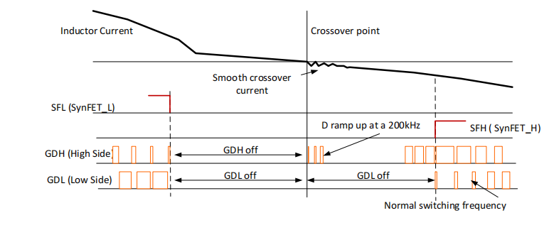
The above figure shows the totem pole drive waveform, GDH and GDL are high-frequency tube drive waveforms, SFL is low-frequency tube drive waveform, Inducor Current is inductor current, and Crossover point is the zero-crossing point.
Before zero-crossing, the outputs of all four gate drivers GDL/GDH/SFL/SFH are turned off. After zero-crossing, the active transistor (SFL or SFH) of the high-frequency transistor starts working first. Unlike outputting full duty cycle from the beginning, the duty cycle of the active transistor gradually increases from zero to full duty cycle at a PWM frequency of 200kHz until the dead time ends. In this way, the high-frequency transistor can smoothly switch between active and passive states. The soft-start of the active transistor generates a very smooth inductor current to discharge the parasitic capacitance at the midpoint of the low-frequency bridge arm, thereby minimizing or eliminating the current spike at the AC zero-crossing point. The low-frequency synchronous transistor is usually a superjunction MOSFET, whose Coss stores a large amount of energy, resulting in a large zero-crossing current spike. The zero-crossing dead time is ±100us, which can prevent potential short circuits when the AC sampling signal is close to 0V and may be interfered with by noise.
1.7 What are the differences between PFC operating modes?
There are two main operating modes of PFC: CRM (Critical On-Mode) and CCM (Continuous On-Mode). CRM is widely used in low-power applications around 300W.
The characteristics of CRM mode PFC mainly include the following:
Zero-current power switch conduction: In CRM mode, the power switch conducts with zero current, which helps reduce switching losses and improve efficiency.
Linear inductor current rise: When the switch is on, the inductor current rises linearly.
Higher conducted interference at low frequencies: Although controllers using CRM PFC can easily modify the feedback section, this method results in higher conducted interference at low frequencies.
Adjustable switching frequency: CRM mode allows changing the switching frequency at the zero crossing of the sine wave, and the switching frequency can be made very high. However, the IC usually internally limits the upper frequency limit to prevent EMI testing failure.
CCM is widely used in high-power applications.
A significant feature of CCM mode is that its current flows continuously, almost DC, and the ripple is very small. This continuous flow of inductor current helps reduce switching noise and improve power supply efficiency and stability. Compared to DCM mode, CCM mode is more suitable for high-power applications.
II. Introduction to Silicon Carbide and Positive/Negative Power Supply Design
2.1 What is Silicon Carbide?
Silicon carbide MOSFETs use silicon carbide (SiC) semiconductor material, while ordinary MOSFETs use silicon material. Silicon carbide has excellent properties such as high melting point, high hardness, high thermal conductivity, high radiation resistance, and high-temperature stability, while silicon material does not have these characteristics.
In terms of characteristics, silicon carbide MOSFETs have faster switching speeds, enabling higher frequency and higher efficiency power conversion. It has higher electric field strength and lower on-resistance, better electromagnetic interference resistance, and is suitable for high-temperature, high-power, high-frequency, and high-voltage applications.
In terms of working principle, silicon carbide MOSFETs have higher electric field strength and higher leakage current, resulting in lower conduction losses under high-voltage conditions. The working principle of ordinary MOSFETs is based on the substrate injection concept or induction concept, while silicon carbide MOSFETs have higher electric field strength and switching speed.
2.2 Why does silicon carbide (SiC) require positive and negative power supply drive?
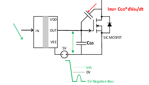
SiC MOSFETs are primarily used in OBC DC/DC systems for high-voltage and high-switching applications, resulting in a significantly higher dVds/dt ratio during switching compared to ordinary Si MOSFETs. Taking a bridge circuit as an example, during the rapid turn-on of the upper MOSFET and turn-off of the lower MOSFET, the Vds of the lower MOSFET increases. At this time, charge is transferred to the gate of the lower MOSFET through the Miller capacitance Cgd, causing a small spike in the gate voltage. Depending on the manufacturer and channel technology, the threshold voltage of SiC MOSFETs is generally between 2V and 5V. If the voltage rise caused by crosstalk during this process exceeds the turn-on threshold voltage of the SiC MOSFET, it may cause the lower bridge arm to turn on incorrectly, leading to shoot-through between the upper and lower bridge arms, resulting in serious consequences such as system short circuit damage.
To mitigate the risk of bridge arm shoot-through during switching, SiC MOSFETs typically require positive and negative voltage drives. Negative voltage turn-off ensures that even small voltage spikes during turn-off will not exceed the threshold voltage, preventing the MOSFET from turning on. The diagram below shows an auxiliary power supply driver requiring input pulses.
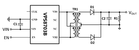
This project uses the VPS8703B full-bridge driver chip. The VPS8703B is a transformer driver specifically designed for small-size, low-standby-power micropower isolated power supplies. With only simple input/output filter capacitors, an isolation transformer, and a rectifier circuit, it can achieve isolated power supplies with input voltages from 6 to 30V, various output voltages, and output power from 1 to 10W. The maximum input voltage is 30V, compared to the Texas Instruments SN6505's maximum 5V input voltage, allowing for a wider input voltage range. It also integrates a 250kHz frequency. Isolated positive and negative power supplies are obtained through the transformer output windings, which can also power isolated current and voltage sampling chips.

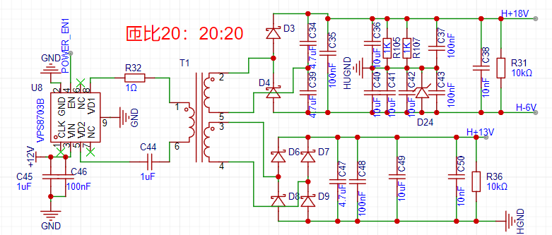
2.3 Why is a capacitor added to the primary side of the auxiliary power transformer?
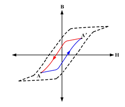
The normal operation of a full-bridge transformer requires meeting the "volt-second balance" requirement, meaning the volt-second product generated during the transformer's excitation process should equal the volt-second product generated during the demagnetization process. If they are not equal, core saturation may occur. Here, B represents the magnetic flux density of the core, and H represents the magnetic field strength inside the core. When switches PM1 and NM2 are turned on, the full-bridge transformer is in the "excitation" stage, and the magnetic flux density continuously increases along the arrow direction from A to A'. At the moment when PWM1 and PWM2 are turned off, the magnetic flux density reaches its positive maximum value A'. When switches PWM2 and PWM1 are turned on, the full-bridge transformer is in the "demagnetization" stage, and the magnetic flux density continuously decreases along the arrow direction from A' to A. At the moment when PM2 and NM1 are turned off, the magnetic flux density reaches its negative maximum value A. The magnitude of the magnetic flux density B is mainly determined by the product of the voltage amplitude Vp of the transformer's primary winding during the switch-on process and the switch-on time Ton, i.e., Vp*Ton, commonly referred to as the "volt-second product." The normal operation of a transformer requires adherence to the "volt-second balance" principle, meaning the volt-second product generated during the transformer's excitation process should equal the volt-second product generated during the demagnetization process. If they are not equal, a bias magnetization phenomenon will occur. As the converter continues to operate, the accumulation of bias magnetization energy will eventually cause the magnetic flux density of the core to gradually increase in the direction of the bias magnetization, exceeding the saturation magnetic flux density range of the magnetic element, ultimately leading to core saturation and inability to operate normally.
In short: the absence of a DC blocking capacitor may cause bias magnetization, bias magnetization will lead to magnetic saturation, and magnetic saturation will cause a sharp increase in current, burning out the device. Of course, the VPS8703 has overcurrent protection, so a capacitor is not necessary; adding a capacitor may result in a decrease in output voltage and power.
2.4 Why is an isolation driver necessary?
As a semiconductor integrated circuit (IC), isolation devices allow data and power to be transmitted between high-voltage and low-voltage units while preventing any dangerous DC current or uncontrolled transient current from flowing out of the grid. A well-known example is lightning strikes. Isolation can break ground loops formed in circuits with high energy flow. There are several isolation methods. Among all isolation methods, current isolation is a method that provides protection against large potential differences.
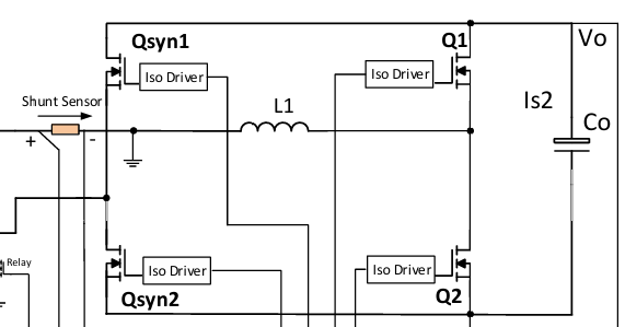
Because the ground of the totem-pole PFC control circuit fluctuates with the frequency of the input voltage, the PFC output voltage needs to be sampled using a high-voltage differential operational amplifier. All power devices require isolated drivers.
2.5 How to select a silicon carbide MOSFET?
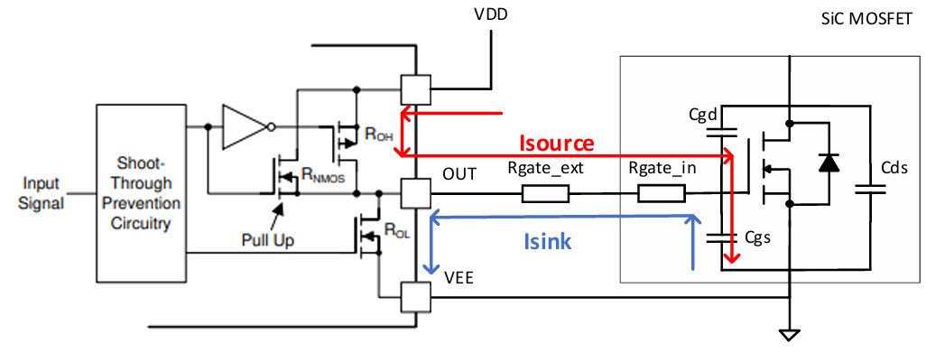
When selecting a silicon carbide MOSFET, pay attention to parameters such as Ciss, Corss, and Qg. Since silicon carbide MOSFETs have high switching frequencies, these parameters will affect their switching losses. Ron determines the conduction losses. When using a driver, we should also pay attention to the drive current, carefully calculate, and select appropriate Rg turn-on and turn-off resistors.
Driver ICs typically charge and discharge the gate capacitor using source current and sink current to switch MOSFETs or IGBTs. To achieve the fast switching characteristics of SiC MOSFETs, resulting in lower switching losses and higher switching frequencies, a larger drive current is usually required.

By observing Vgs and Vds, we can determine whether the value of Rg is appropriate.
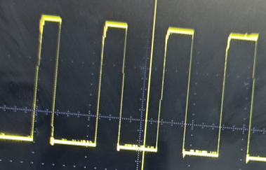
The Vgs rising edge in the above figure has a significant delay at the top. This indicates that Rg is too large. The above
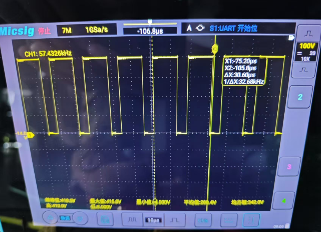
figure shows the waveform after adjusting Rg, with neither overshoot nor delay. Overshoot will exceed the maximum voltage of silicon carbide (SiC), but the duration is generally very short, and SiC can still operate, only with a reduced lifespan. Some SiC datasheets specify the overvoltage operating time. The
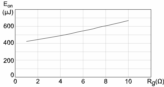
above figure shows the relationship between turn-on loss and Rg value. The next chapter will detail how to calculate Rg.
III. Theoretical Calculation
3.1 Current Limiting Sampling Resistor Value:
A suitable resistor value can provide a reasonable range of power protection. Note the resistor's power rating.

3.2 Inductor Value Calculation:

It is worth noting that the inductor's inductance should still have 70% of its original value at 20A DC bias. Refer to the inductor's datasheet. This project uses a 360uH inductor, which still has 320uH of inductance at 20A.
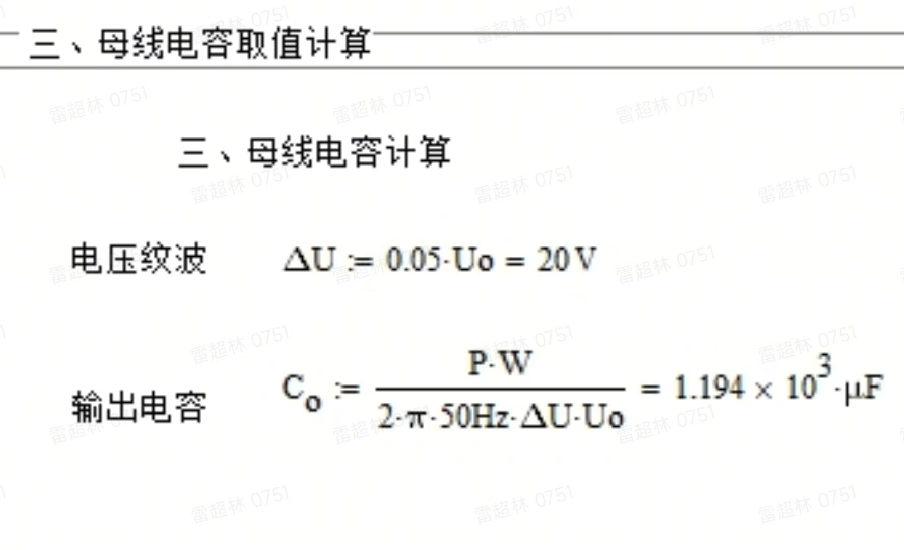
3.3 Output Capacitor Calculation:
Multiple output capacitors should be connected in parallel whenever possible. Remember to calculate the power rating of the bleeder resistor. A 100nF decoupling capacitor needs to be added at the output to reduce high-frequency ripple
. 3.4 The driving resistor for
the MOSFET can be adjusted based on the waveform; 10 ohms is recommended

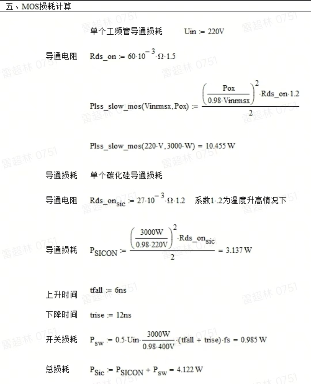
. 3.5 Calculation of switching and conduction losses:
In PFC hard switching, switching and conduction losses are roughly equal in low-to-medium power applications (1-10kW). In high-power applications (above 10kW), conduction losses dominate because of the synchronous rectifier's ZVS turn-on and turn-off. At power frequency, due to the very low frequency, conduction losses dominate. Switching losses are related to Vds rise time, fall time, and frequency.
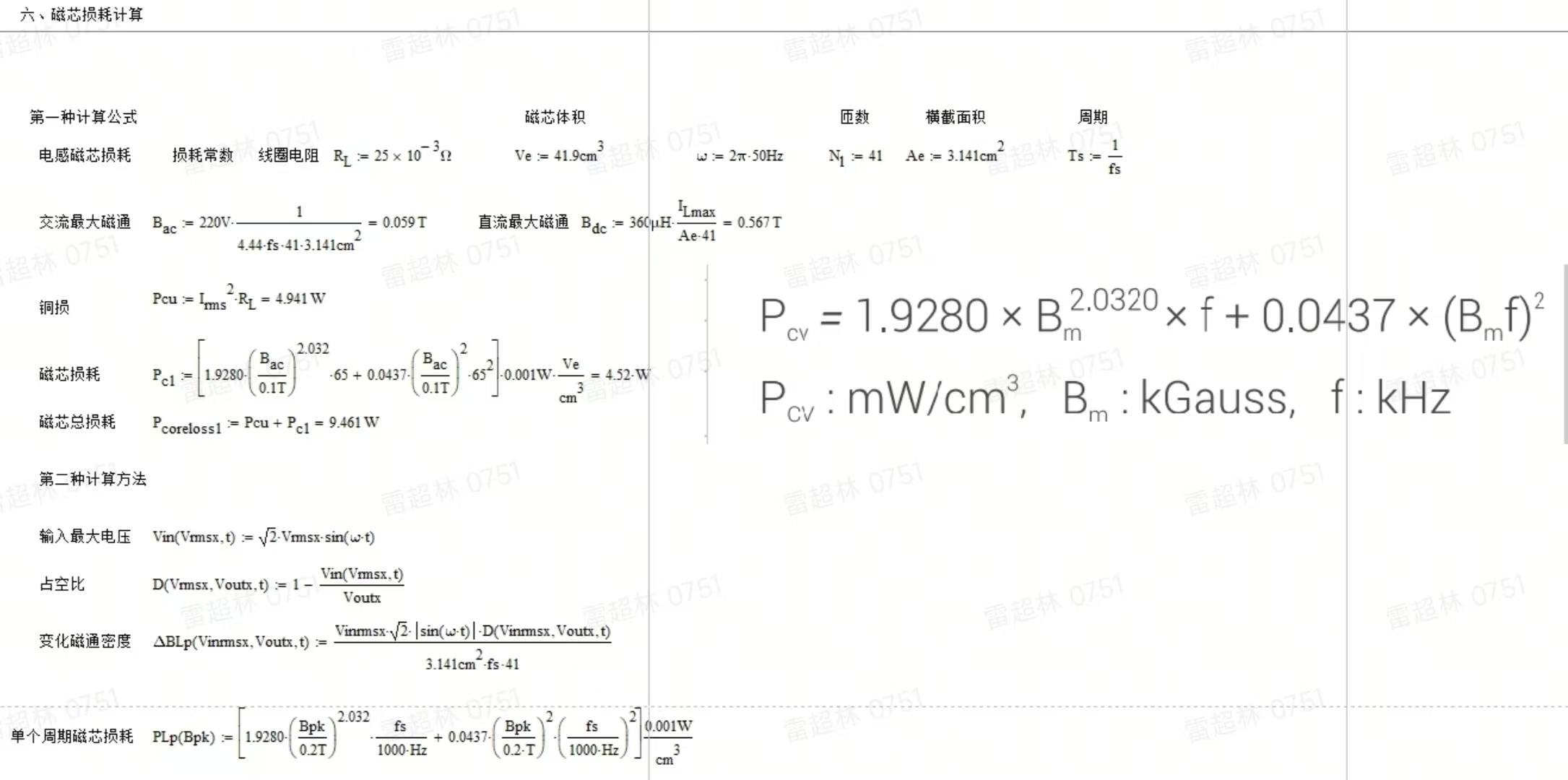
3.6 Calculation of inductor core losses:
There are many methods for calculating core losses, primarily the Steinmetz formula and the loss formula provided by core manufacturers based on material testing, which is generally a fitted formula.
The hysteresis loop H (where B is magnetic flux density and H is magnetic field strength) of the core material is a function of frequency /'. The total core loss consists of three parts: hysteresis loss, eddy current loss, and residual loss. Residual loss at high frequencies mainly includes losses caused by size resonance, domain wall resonance, and natural resonance [l], but its proportion is small. From the dynamic hysteresis loop, it can be seen that the higher the operating frequency, the larger the hysteresis loop, and the greater the loss per unit mass. When describing the core loss of a transformer using the loss separation method, it can be decomposed into static hysteresis loss, dynamic eddy current loss, and residual loss P.
The core loss density (unit: W/kg) represents the core loss per unit mass. The classic method for describing high-frequency loss density is the Steinmetz formula,

where K is the loss coefficient, f is the frequency, B is the magnetic flux density, and a and β are loss constants.

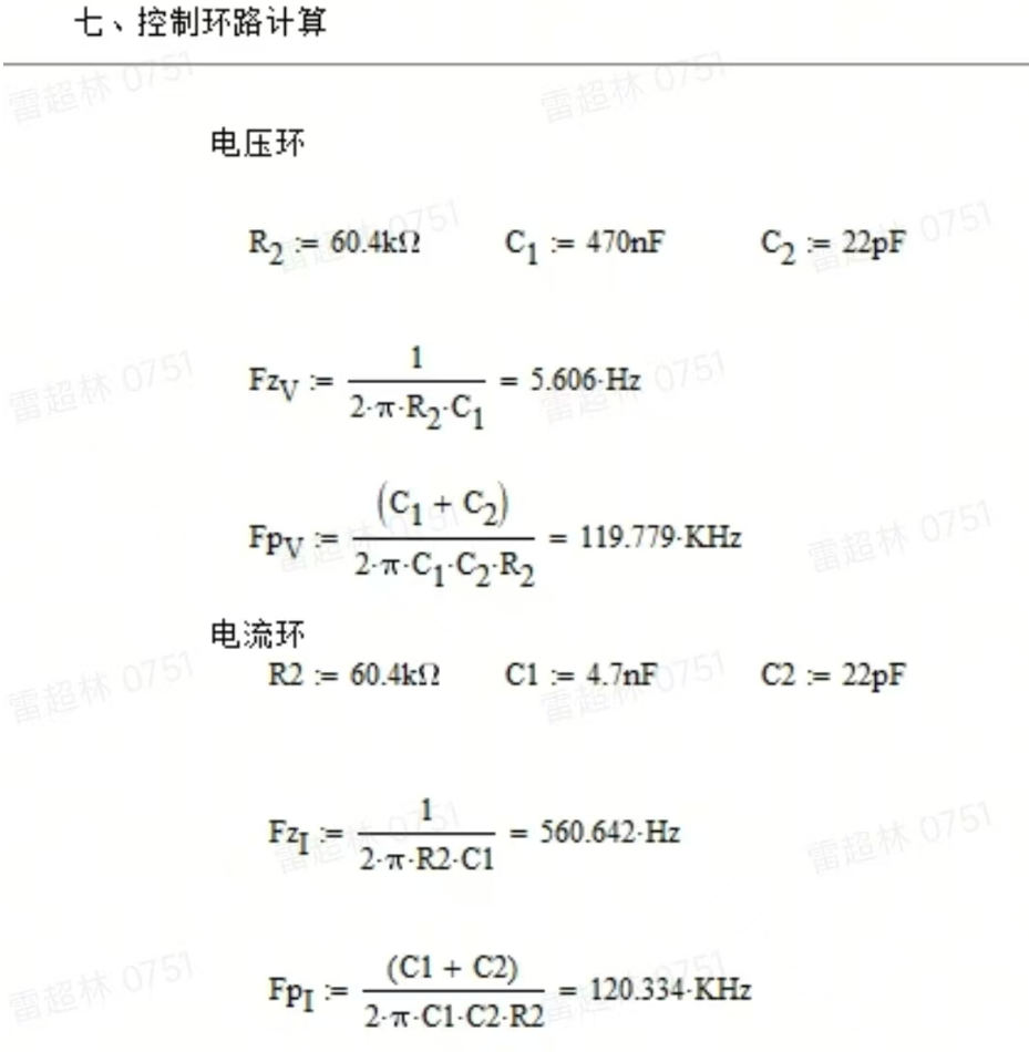
3.7 Zero-Pole Compensation Calculation:
This circuit uses a type II compensator for compensation, with one zero and one pole. Due to the 2x power frequency ripple on the output voltage, the voltage sampling crossover frequency was set to 5Hz to reduce the impact on the circuit voltage loop. The values of the compensation network are related to the output load, capacitor ESR, etc., and need to be adjusted according to different operating conditions in practice. In the previous project, when setting the voltage of the 220/380V adjustable power supply, it was found that the output of EG1163S was unstable below 5V, and the Vgs waveform showed large and small waves. The loop crossover frequency and phase margin were tested, the loop response was reduced, the phase margin was increased, and the 10nF feedforward capacitor was changed to 20nF to solve the problem of unstable voltage regulation.
IV. Waveform Analysis:

High-frequency tube waveform ,
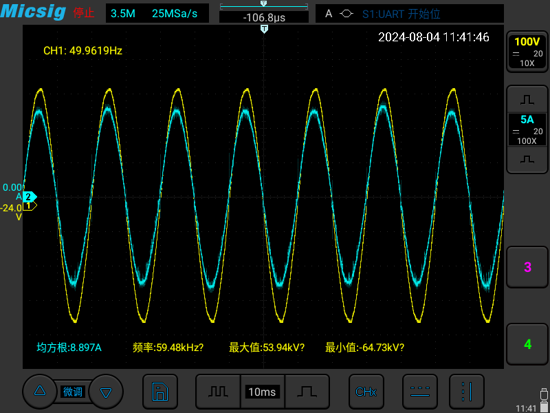
voltage and current waveforms,
high-frequency tube waveform,

low-frequency tube waveform.
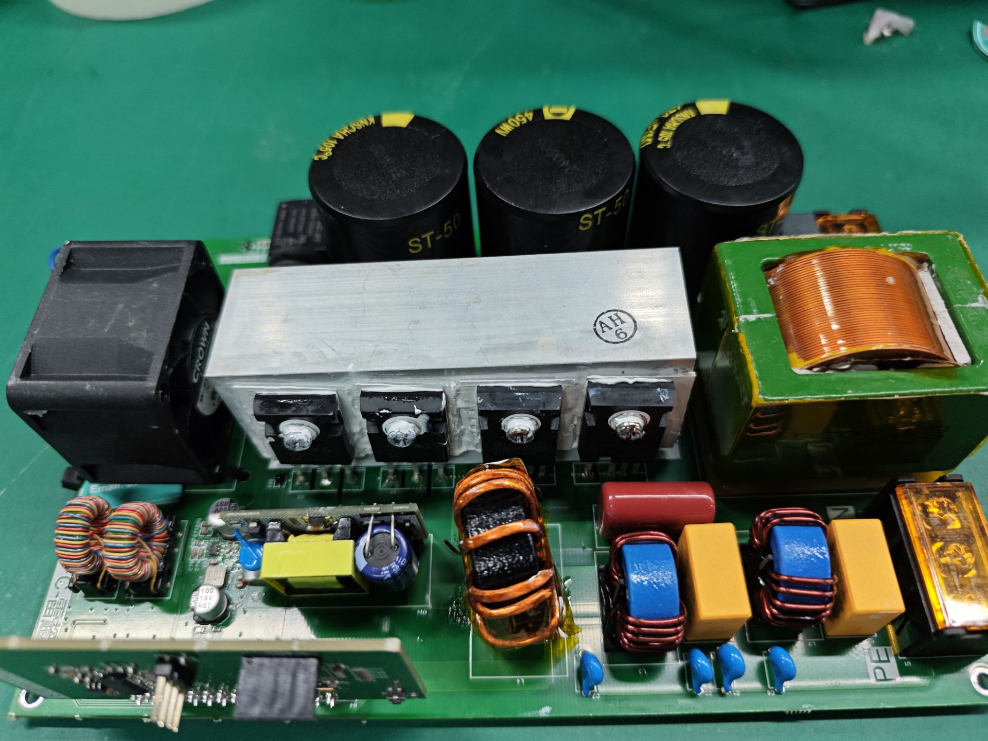
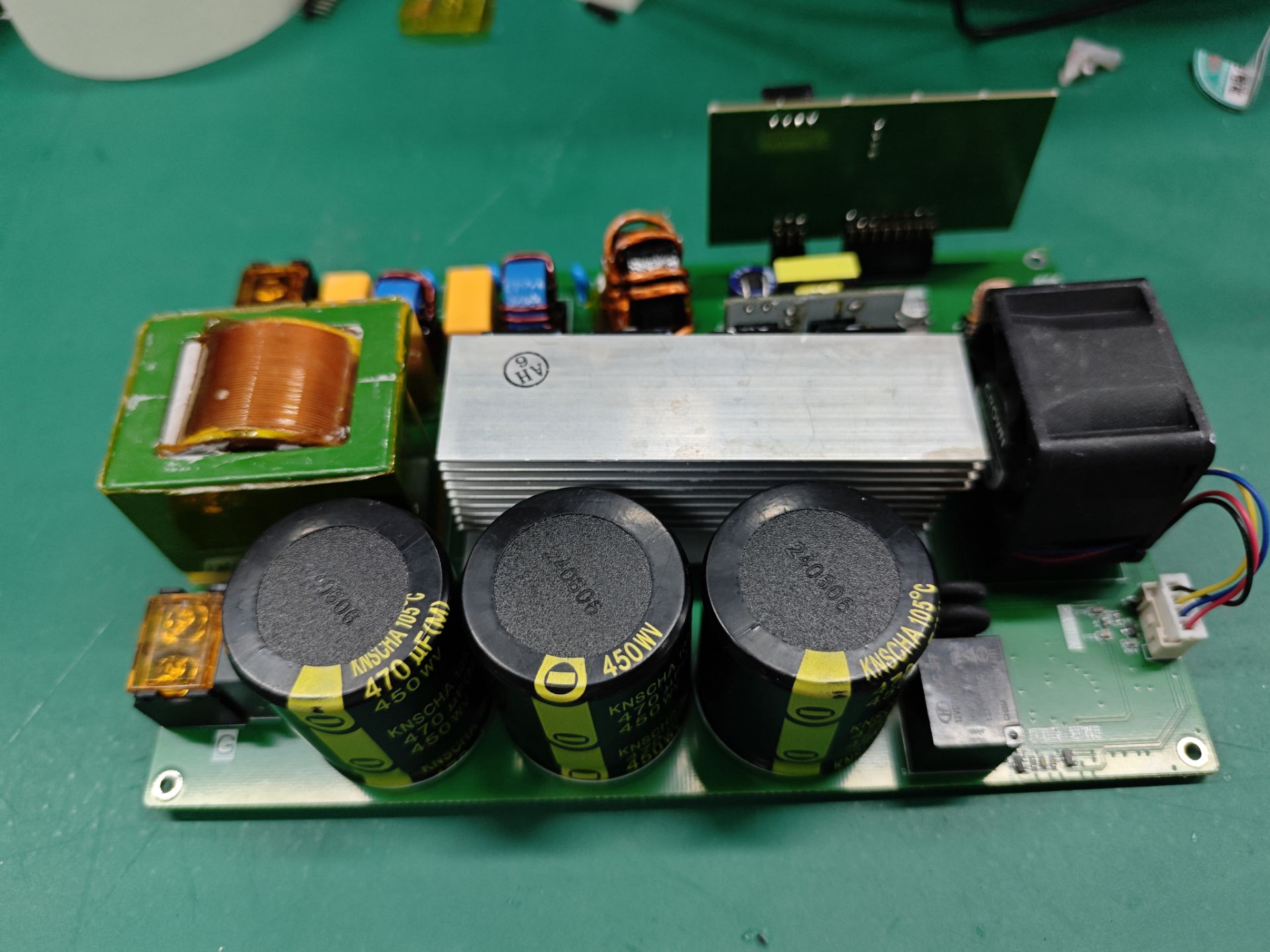
V. Physical Demonstration:

The maximum temperature of the 3KW unit after 10 minutes is the inductor temperature, 34.6 degrees

Celsius. The maximum temperature in 120 minutes is the inductor temperature, 43.8 degrees.

The maximum power is 3.5kW and can run for a long time.
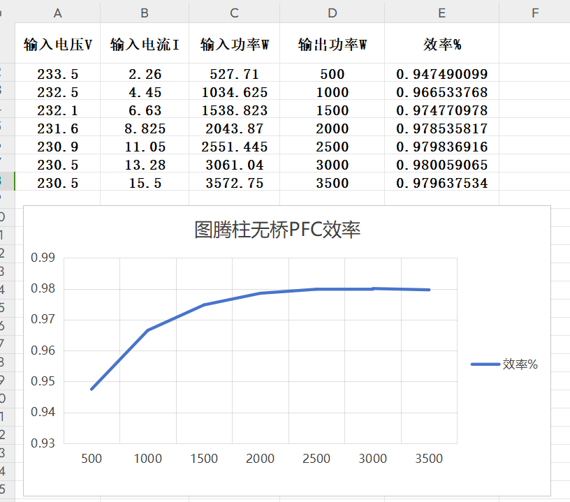
The efficiency curve is around 98%.
At this time, the power frequency tube has an internal resistance of 60mΩ, the high frequency tube has an
internal resistance of 27mΩ, and the CISS is 2nF. The power frequency tube is replaced with a 30mΩ internal resistance, and the high frequency tube remains unchanged. The test result is:

3000/(231.2*13.15)= 0.98675.
The efficiency increases from 98% to 98.675%. Then, the high frequency silicon carbide is replaced with a 15mΩ internal resistance, CISS is 9nF, and the drive resistor Rg is changed to 4.7Ω. After testing, 3000/(230.8*13.25)=0.981, which is 18W more. The loss efficiency decreases from 98.675% to 98.1%. Physical picture Reference [1] Lu Fangcheng, Guo Yunxiang. Comparative analysis of calculation methods of iron loss of medium frequency transformer under non-sinusoidal excitation [J]. High Voltage Technology, 2017, 43(3):808-813. DOI:10.13336/j.1003-6520.hve.20170303016. [2] Xi Binsheng. Research on Vibration and Loss Characteristics of Nanocrystalline Iron Center Medium Frequency Transformer [D]. Hubei: Three Gorges University, 2023. [3] 4kW Single-Phase Totem PFC Reference Design Using C2000 and GaN, Texas Instruments [4] 4kW GaN Totem PFC Reference Design for Electrical Appliances, Texas Instruments [5] 7.4kW Bidirectional On-Board Charger Reference Design for Electric Vehicles/Hybrid Electric Vehicles Using GaN, Texas Instruments [6] How to Adjust Silicon Carbide MOSFET Drive to Reduce Power Loss, STMicroelectronics [7] OBC DC/DC SiC MOSFET Drive Selection and Power Supply Design Points, Texas Instruments [8] Silicon Carbide Gate Driver: A Disruptive Technology in the Power Electronics Industry, Texas Instruments


 京公网安备 11010802033920号

 74F74SCX


