For a video demonstration of the module's weighing capabilities, please visit Bilibili: https://www.bilibili.com/video/BV1NT421y7vf/?spm_id_from=333.999.0.0&vd_source=4c57166c6142504cc135c2135bf9844e
Module purchase link: https://item.taobao.com/item.htm?abbucket=12&id=790227004246&spm=a230r.7195193.1997079397.6.5abe7dfbTM2wkt&skuId=5394129133014
Open-source code address: https://github.com/EggplantPotatoes/weight_control_DSX
Function Description:
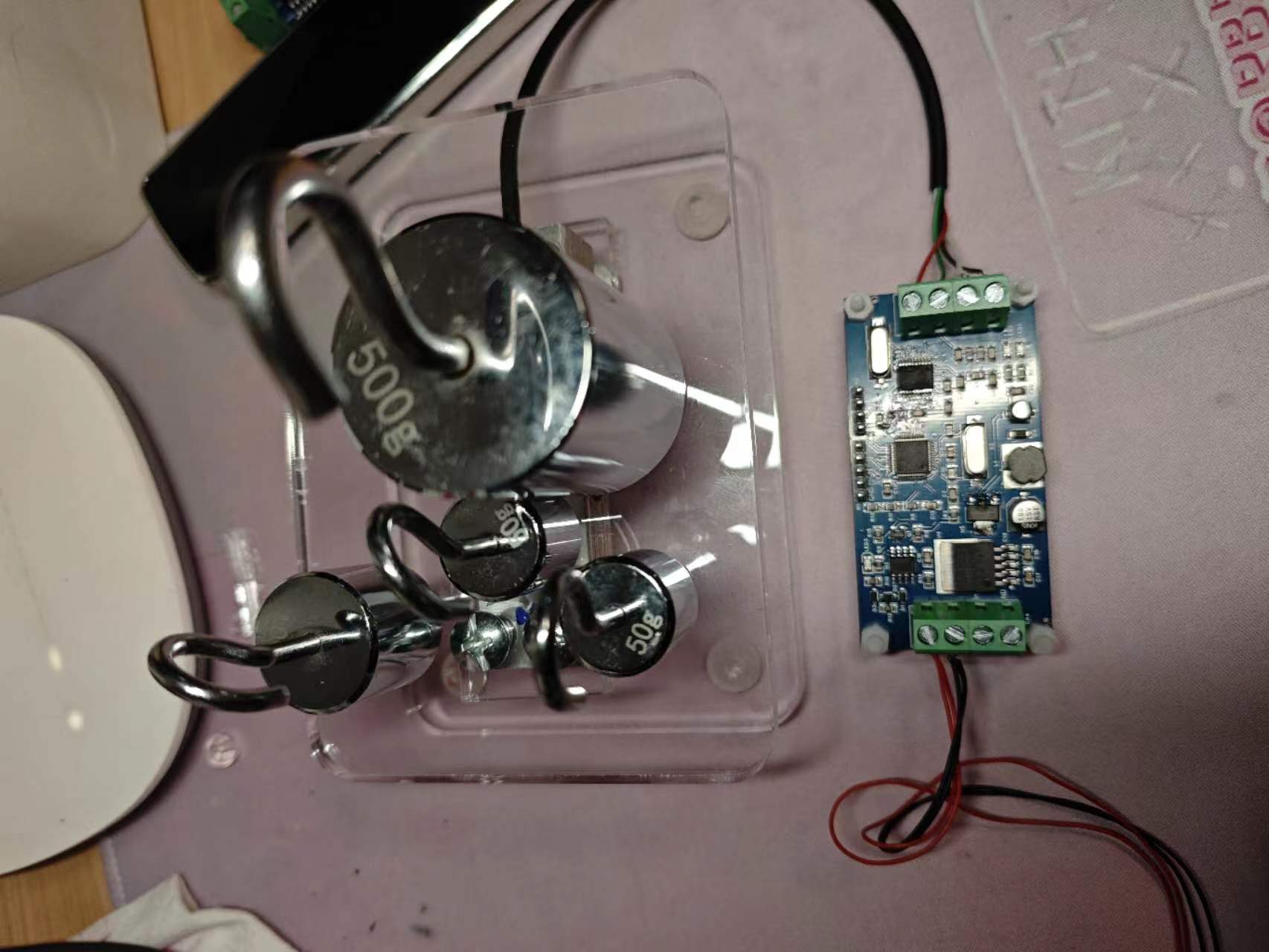
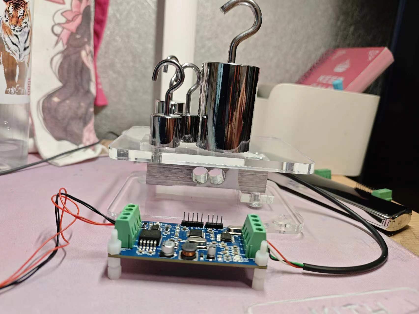
1. This project is a high-precision weighing control module with a weighing accuracy of up to 100,000. Supports RS485 communication and Modbus RTU communication protocol.
2. 7~44V wide voltage power supply.
3. The main control MCU uses STM32F103C8t6, and the AD acquisition chip uses CS5530, 24-bit sampling.
4. The communication protocol supports zeroing, reading weight, reading raw AD data, weight calibration, and communication address modification.
5. ADC sampling uses mean filtering and Kalman filtering.


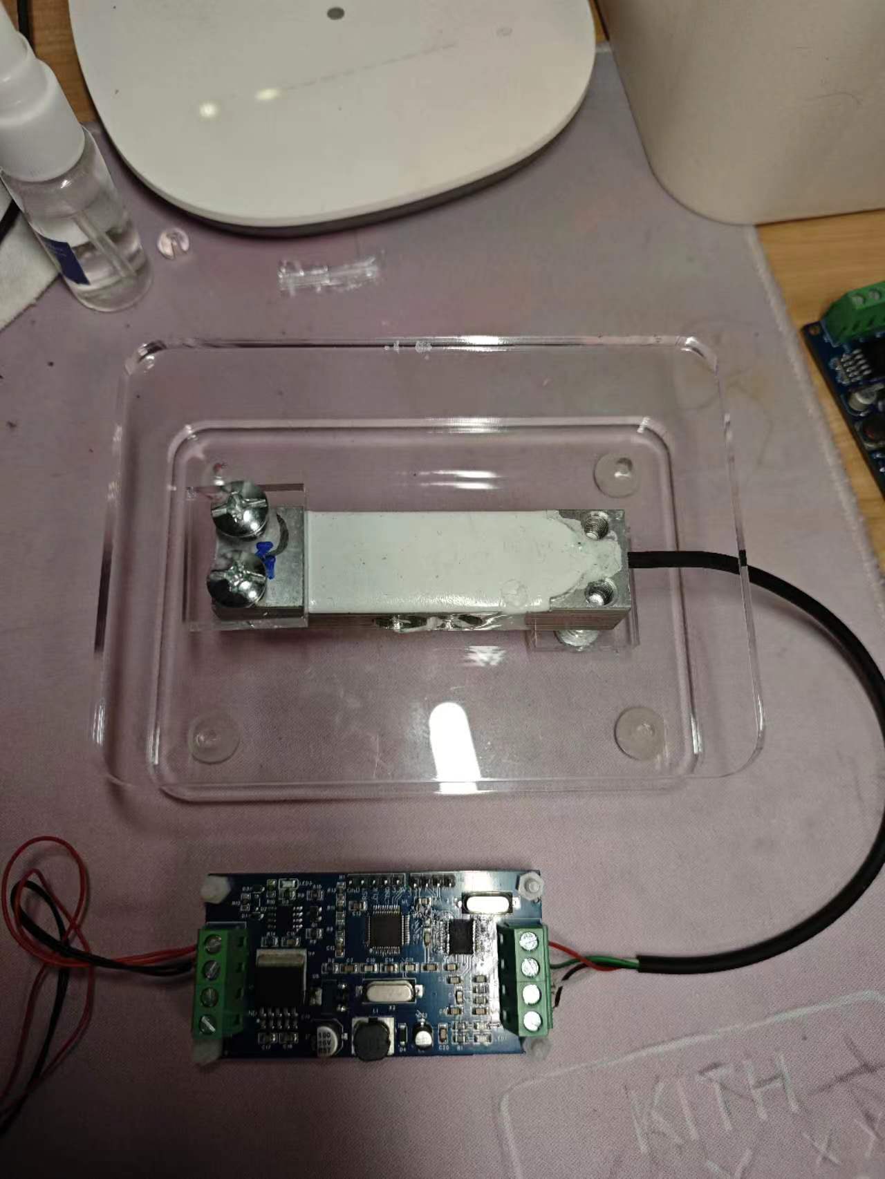
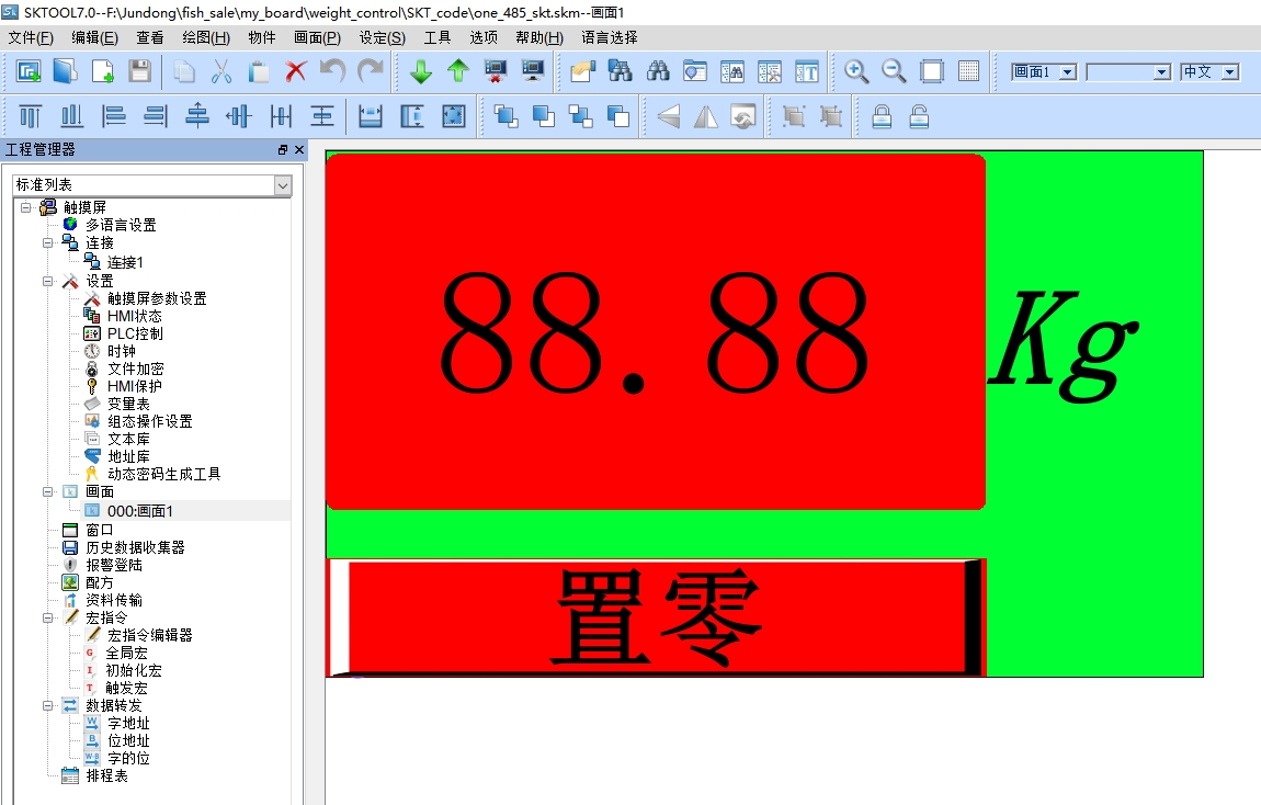
Host Computer Introduction :
There are two types of host computers: one is a self-developed PC,

and the other uses the SK-070QT display and control system.

488b9069a152441c7ae2a3b73b9d3d79.mp4
PDF_High-precision AD acquisition module, weighing module, electronic scale module.zip
Altium High-Precision AD Acquisition Module Weighing Module Electronic Scale Module.zip
PADS High-Precision AD Acquisition Module Weighing Module Electronic Scale Module.zip
BOM_High-precision AD acquisition module weighing module electronic scale module.xlsx
95005
Low-cost closed-loop current sensor
A closed-loop Hall effect current sensor is used to detect the current. The signal is then sent to an oscilloscope.
Because motor debugging requires current observation, I initially wanted to build a Rogowski coil current probe following an online open-source tutorial. However, winding the Rogowski coil didn't go smoothly, so I switched to using a readily available closed-loop Hall effect sensor. The solution is relatively simple, just amplifying the signal through an instrumentation amplifier circuit. Currently, there's an AC attenuation issue; I tried to solve it, but it didn't help much, so I abandoned it.
I used a ±75A current sensor from TB (Taiwan), with a current range of 2.5±2V and a detection unit of DC~200kHz. The signal was amplified and converted to two levels, 200mV/A and 50mV/A, using an operational amplifier. It was connected to an oscilloscope via an SMA-J to BNC-J cable. The 5V power supply uses a Type-C interface, and the power supply and output power are isolated, effectively ensuring the oscilloscope's safety. Actual testing compared to a Tektronix TCP0150 revealed that the DC performance was basically the same, but there was attenuation above 10kHz in the AC. Testing under 10A 25kHz conditions showed attenuation of less than 1A, which is perfectly adequate for daily motor debugging. Total cost less than 100.
Current probe ±75A, note that the output range needs to be changed to 2.5±2: HCS-ES5 closed-loop Hall current sensor, high reliability and anti-interference - Taobao (taobao.com)
Housing: Aluminum alloy housing, split aluminum housing, battery box, circuit board PCB box, aluminum profile housing, custom opening 50*20 - Taobao (taobao.com)
0d9a7eb6bf7f84b2c9560c13f2db4878.jpg
0d9a7eb6bf7f84b2c9560c13f2db4878.mp4
PDF_Low-cost closed-loop current sensor.zip
Altium - Low-cost closed-loop current sensor.zip
PADS_Low Cost Closed-Loop Current Sensor.zip
BOM_Low-cost closed-loop current sensor.xlsx
95008
A tutorial on STM32 self-balancing car that even a paramecium can learn
This tutorial on making an STM32 self-balancing car is so easy even a complete beginner can learn it. It includes all the open-source code, PCB layout, and bill of materials, along with accompanying tutorial videos on Bilibili. It provides both HAL and standard library code, and its modular plug-in design is perfect for beginners.
This STM32 self-balancing car features self-balancing, Bluetooth remote control, and ultrasonic obstacle avoidance. It can be easily replicated using tutorials. The total cost is around 200 RMB.
You can find open-source videos and purchase the finished product on Bilibili (uploader: 会飞的鱿鱼03).
Open-source video tutorial links: 【STM32 Self-Balancing Car Tutorial (Basic Edition) - Bilibili】 https://b23.tv/P2qUKXY
【STM32 Self-Balancing Car Tutorial (Software Edition) - Bilibili】 https://b23.tv/9OwPClN
For materials, software code, and a hardware parts list, join QQ group: 752273834, password: 会飞的鱿鱼03.
Any questions can be discussed in the QQ group or by contacting the group owner privately.
QQ group number: 752273834.txt
Materials List.xlsx
3. Acrylic board file.rar
1. STM32 self-balancing scooter source code.rar
Altium-based STM32 self-balancing robot tutorial that even a novice can learn. (zip file)
PADS_Even a Paramecium Can Learn STM32 Balance Car Tutorial.zip
BOM_Even a Paramecium Can Learn to Make an STM32 Balance Car Tutorial.xlsx
95009
7135-LED flashlight driver
The flashlight driver uses a 4*7135 diode, which can accommodate up to four 7135 diodes. The current draw is approximately 1.5A. One Schottky or switching diode (17mm diameter, 1.6mm thickness) is needed for reverse polarity protection.
The flashlight driver uses 7135 chips in 4, 6, and 8 configurations.
Each 7135 chip provides 350mA of current. The more 7135 chips connected in parallel, the greater the current provided.
Four chips provide approximately 1.5A, which has been verified. The PCB design for 6 or 8 chips is unverified.
A Schottky diode or switching diode can be used on the PCB to prevent reverse connection and ensure the battery is installed correctly. The diameter is 17mm, and the recommended thickness is 1.6mm.
PDF_7135-LED flashlight driver.zip
Altium_7135-LED flashlight driver.zip
PADS_7135-LED Flashlight Driver.zip
BOM_7135-LED Flashlight Driver.xlsx
95010
New 1C1A desktop charger based on IP6520 and IP6505 standards
The new 1C1A desktop charger, based on IP6520 and IP6505 standards, adds fast charging and power status indicators compared to the old version. It supports DC input of 7.1V-32V, with 13V-24V recommended, and features adaptive input polarity.
This project is an upgrade of the old desktop charger!
IP6520 Introduction:
The IP6520 is a step-down converter with integrated synchronous switching, supporting multiple fast charging protocols, Type-C output, and USB PD2.0/PD3.0 (PPS) protocols, providing a complete solution for car chargers, fast charging adapters, and smart power strips. The IP6520 has a built-in power MOSFET, an input voltage range of 7.1V to 32V, and an output voltage range of 3V to 12V, providing a maximum output power of 25W. It can automatically adjust the output voltage and current according to the detected fast charging protocol. Typical output voltages and currents are: 5V/3A, 9V/2.5A, and 12V/2A. The IP6520's PD output has CV/CC characteristics. When the output current is less than the set value, it outputs in CV mode with a constant output voltage; when the output current is greater than the set value, it outputs in CC mode with a reduced output voltage. The IP6520 features automatic overcurrent point adjustment. After a successful handshake with the high-voltage SCP and fast charging protocol, it supports a maximum output of 10V/2.5A. When the device connected to the IP6520's Type-C interface supports high-voltage SCP, it prioritizes high-voltage SCP output, resulting in higher charging power compared to PD output. The IP6520's output voltage includes line compensation; as the output current increases, the output voltage increases accordingly to compensate for voltage drops caused by connection line impedance. The IP6520 has a soft-start function to prevent inrush current from affecting the stability of the input power supply. The IP6520 supports Type-C interface output, integrates various fast charging protocols, and can automatically identify the fast charging protocol supported by the connected device via CC1/CC2 or DP/DM, then automatically adjust the output voltage and current accordingly. The IP6520 supports the following fast charging protocols: DCP (Apple and BC1.2), Qualcomm QC2.0/QC3.0 (class A), Huawei's FCP and HVSCP fast charging protocols, and Samsung's AFC (MAX 12V) fast charging protocol. The IP6520 supports USB PD2.0/PD3.0 (PPS) output protocols. The IP6520 has multiple protection functions, including input overvoltage and undervoltage protection, and output overcurrent, overvoltage, undervoltage, and short circuit protection.
The IP6520 uses an ESOP-8 package.
It supports DCP/QC2.0/QC3.0/FCP/HVSCP/AFC/MTK PE/PD3.0/PPS up to 25W (IP6520-C-65W20V, maximum 68.25W).
The IP6505
is a buck converter with integrated synchronous switching, supporting 11 fast charging protocols and providing a complete solution for car chargers, fast charging adapters, and smart power strips. The IP6505 integrates a power MOSFET, with an input voltage range of 4.5V to 32V and an output voltage range of 3V to 12V, providing a maximum output power of 24W. It can automatically adjust the output voltage and current according to the detected fast charging protocol. Typical output voltages and currents are: 4V@3.6A, 5V@3.4A, 7V@3A, 9V@2.5A, and 12V@2A. The IP6505 boasts a buck conversion efficiency of up to 97%. The IP6505's output exhibits CV/CC characteristics: when the output current is less than a set value, it outputs in CV mode with a constant output voltage; when the output current is greater than a set value, it outputs in CC mode with a reduced output voltage. The IP6505 features line compensation, increasing the output voltage as the output current increases to compensate for voltage drops caused by connection impedance. It also has a soft-start function to prevent inrush current from affecting the stability of the input power supply. The IP6505 integrates various fast charging protocols, automatically identifying the supported fast charging protocols of connected devices via DP/DM and adjusting the output voltage and current accordingly. Supported fast charging protocols include: DCP (Apple, Samsung, and BC1.2), Qualcomm QC2.0/QC3.0 (class A), MTK PE1.1/2.0, Huawei FCP/SCP, Samsung AFC, and Spreadtrum SFCP. The IP6505 offers multiple protection functions, including input overvoltage and undervoltage protection, and output overcurrent, overvoltage, undervoltage, and short-circuit protection.
The IP6505 is packaged in an ESOP-8 package.
Supports DCP/QC2.0/QC3.0/MTK PE1.1/PE2.0/FCP/SCP/AFC/SFCP up to 24W.
For this project
, PCB1 should be made of FR-4 material, and PCB2 (empty board) should be made of aluminum substrate. A frosted acrylic panel is recommended.
Required components include 4 M2 screws (5mm long), 4 M2 double-ended knurled screw posts (11mm long), 8 M2 single-ended knurled screw posts (3mm thread, 3mm body), and one 3.5mm thick thermal pad.
Installation instructions are omitted here.
For the IP6520 model, the IP6520-C-65W20V option is available (this model supports 20V; pay attention to capacitor voltage rating).
This project is an upgrade of the old desktop charger.
Update Log
2024-04-29: Fixed LED1 polarity error; thanks to @hmjb888 for pointing out the error.
IP6505_datasheet.pdf
IP6520_datasheet.PDF
PDF_New 1C1A Desktop Charger Based on IP6520 and IP6505 Solutions.zip
Altium's new 1C1A desktop charger based on IP6520 and IP6505 standards.zip
PADS New 1C1A Desktop Charger Based on IP6520 and IP6505 Standards.zip
BOM_New 1C1A Desktop Charger Based on IP6520 and IP6505 Solutions.xlsx
95012
XT30 CAN splitter
RoboMaster uses a power distribution board
Note: This is a KiCAD project! Please
ensure
it is used with the baseplate. The bottom copper layer is VCC, and exposed solder joints without covering pose a short circuit risk.
The project drawing shows the effect without a vertical mounting interface. The GH1.25 socket can be directly replaced with either a horizontal or vertical mounting. Therefore, this is for photography purposes.
Note that
the hole positions are consistent with the DJI C-board, and the dimensions are consistent with the official DJI ESC center board.
The vertical XT30 uses a wire-bonding type, and
the horizontal XT30 uses a board-bonding type.
The CAN interface is a GH1.25 2P interface
. Attachments:
KiCAD original project
baseplate SLDPRT file,
baseplate STEP file.
power_deliever_xt30_can.zip
Base plate.SLDPRT
Base plate.STEP
PDF_XT30 CAN Splitter Board.zip
Altium_XT30 CAN Splitter Board.zip
PADS_XT30 CAN Splitter Board.zip
BOM_XT30 CAN Split Board.xlsx
95013
electronic


 京公网安备 11010802033920号

 HLMP-K401-E00VB


