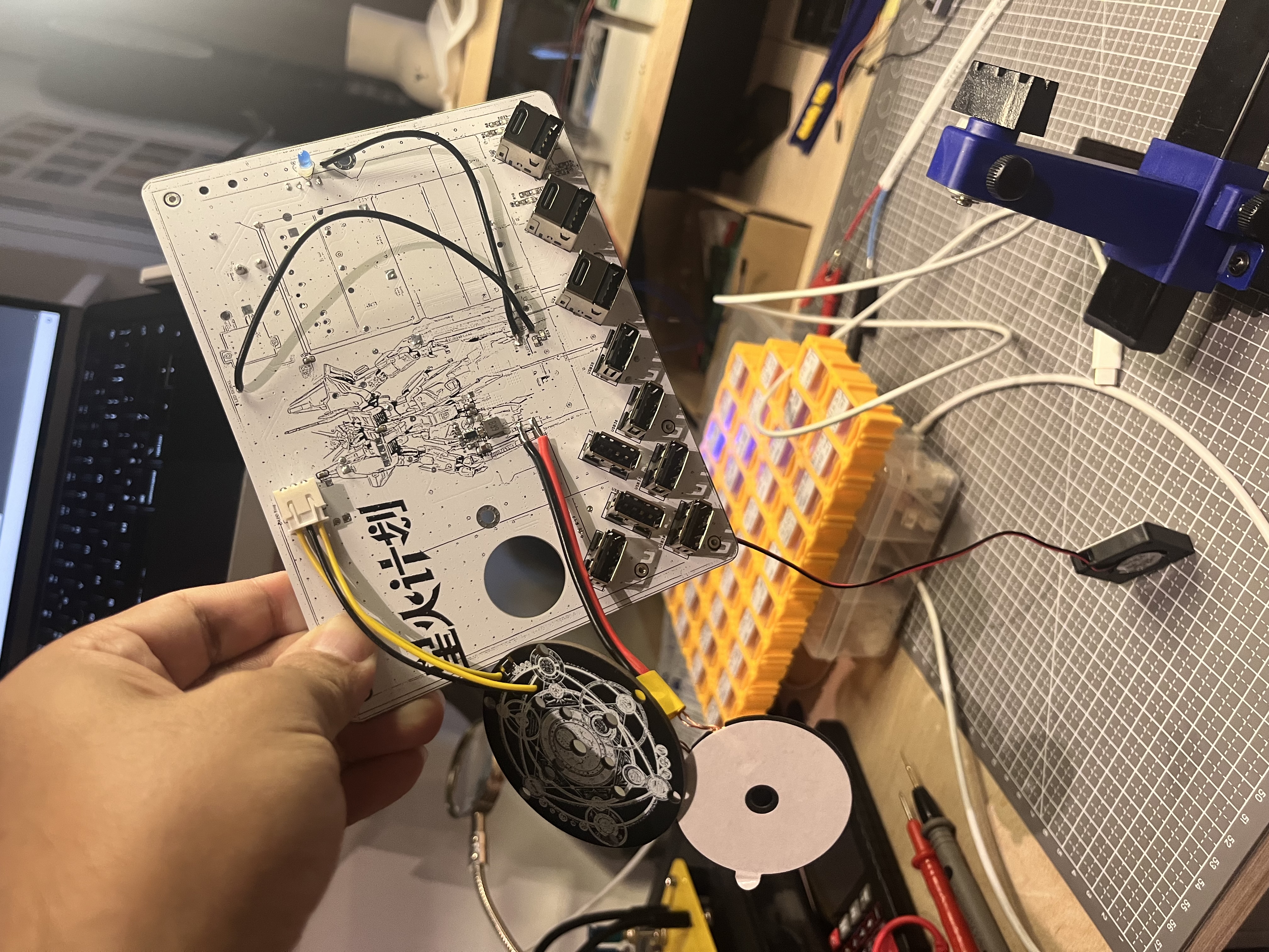
I want to make a USB power supply that can be plugged in however I want, but it can't protrude or warp; the embedding must be perfect, flat, like the keyboard of my Apple MacBook Air laptop—flat and tactile.
It should be wirelessly charging and have a flashy light, but I need to suppress the light while charging;
it can't be too revealing or conspicuous, avoiding being stared at by many. It needs to be placed in a quiet corner against the wall, waiting patiently until I need to charge it. It
needs a very flashy internal casing, but the outer shell must cover it up so it's not easily visible to outsiders. This is the ultimate aesthetic of a tech geek with an art background
! But! Some power supplies are inherently flashy and can't be hidden.
This mainly discusses the power supply box for the power station, but the desktop is also open source, using mostly JLC FA materials. The desktop substrate needs to be purchased from Taobao.
Process video: https://www.bilibili.com/video/BV1UMx4ekEu7/
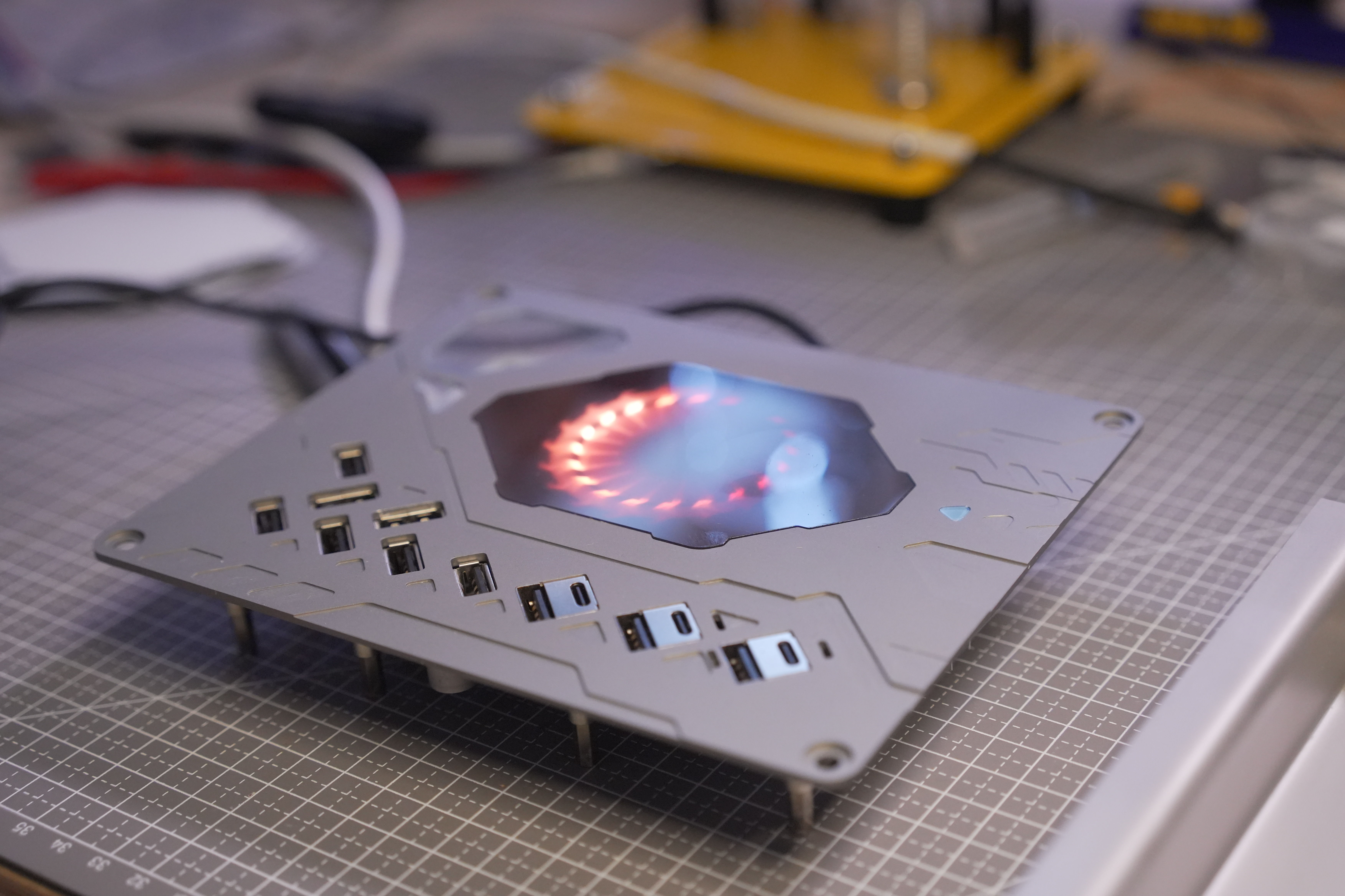
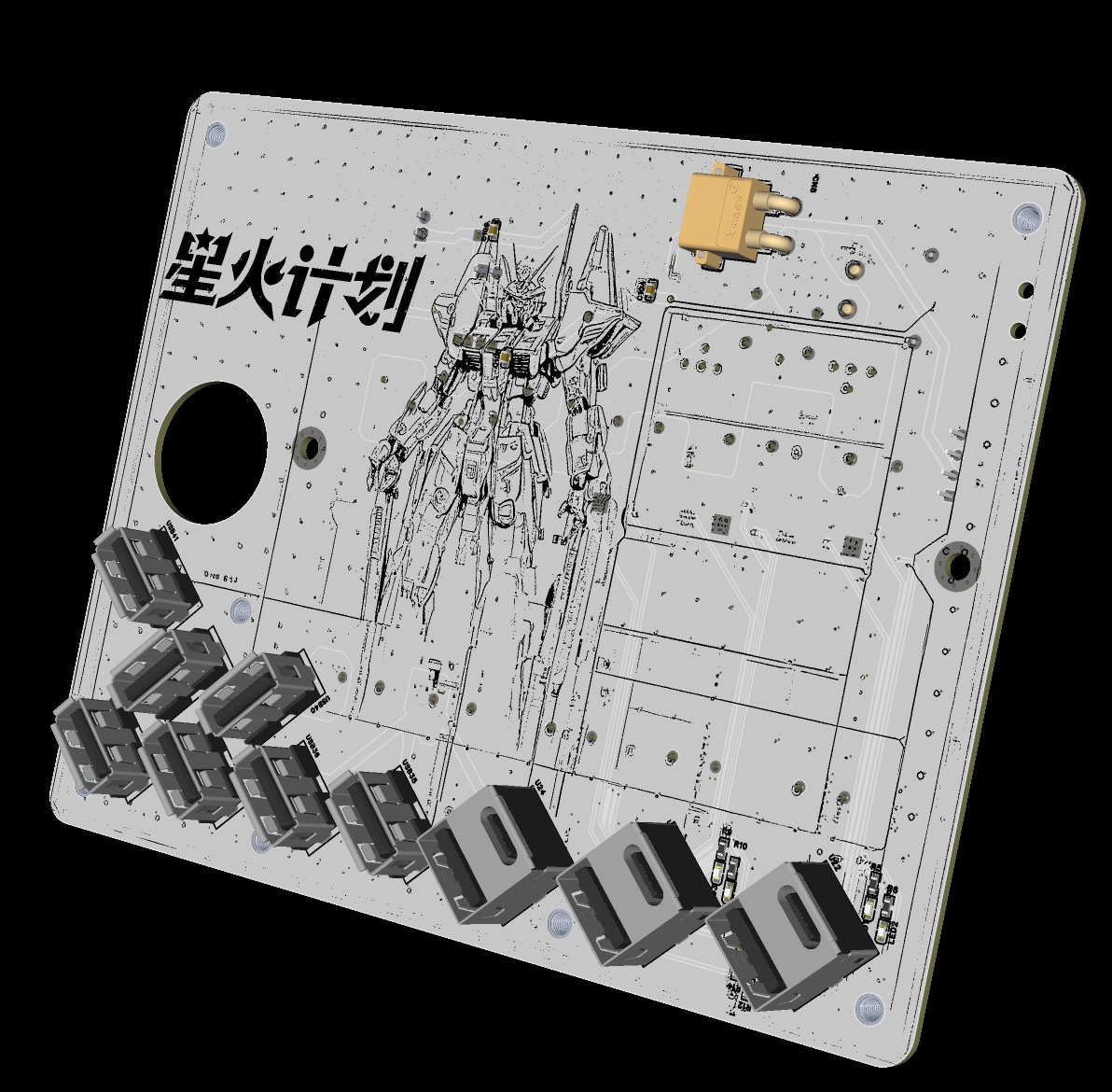
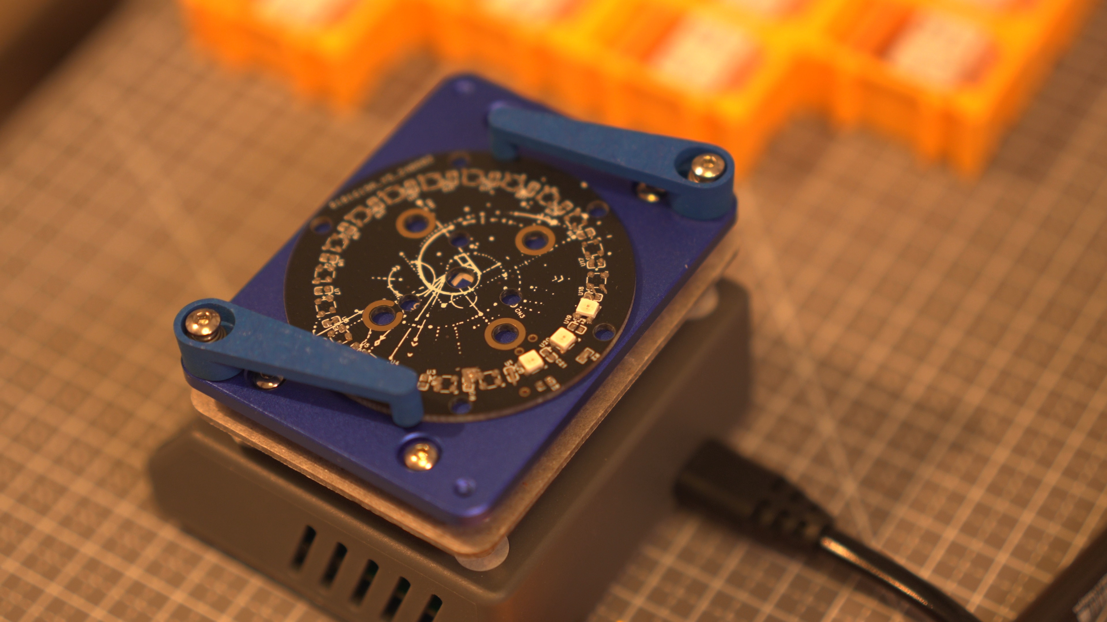
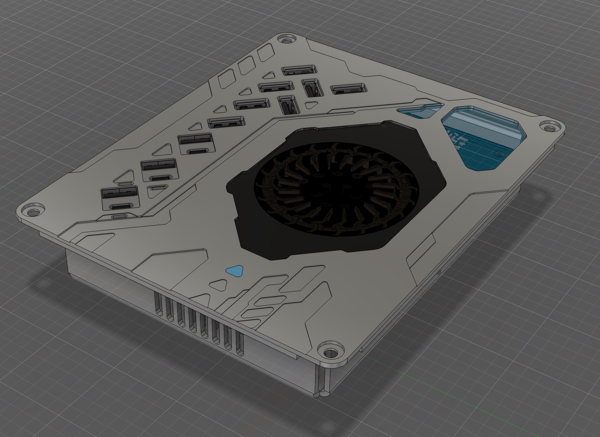
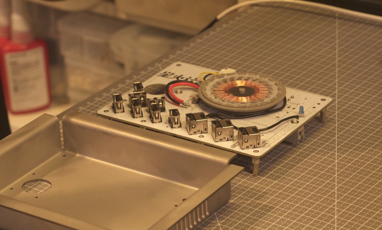
Actual product image (above) PCB + top cover
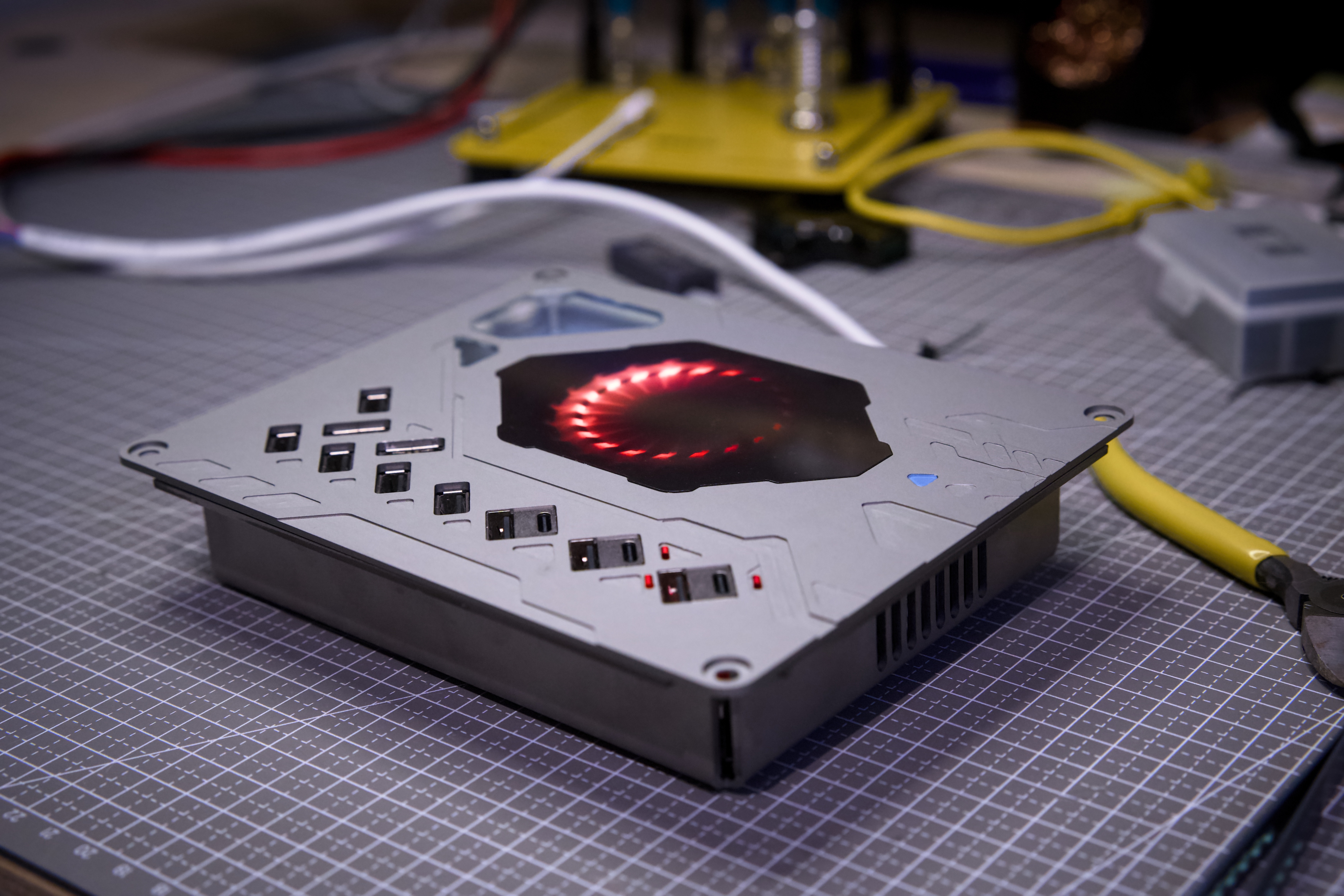
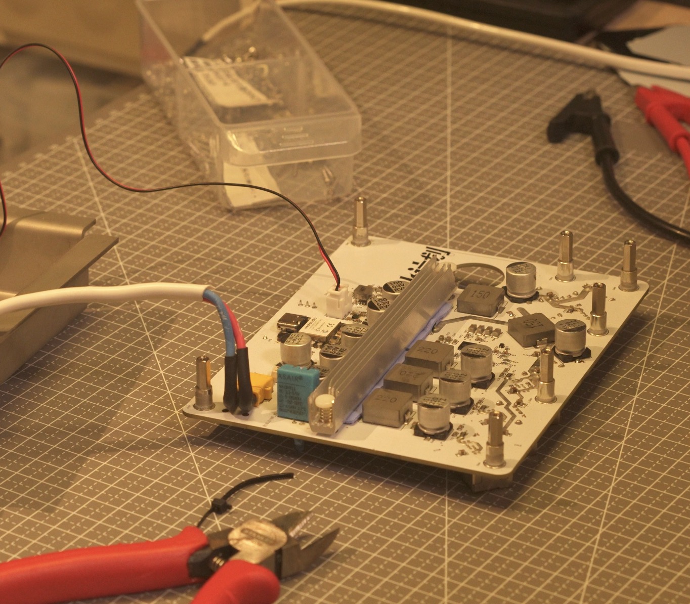
actual product image (above) Completed
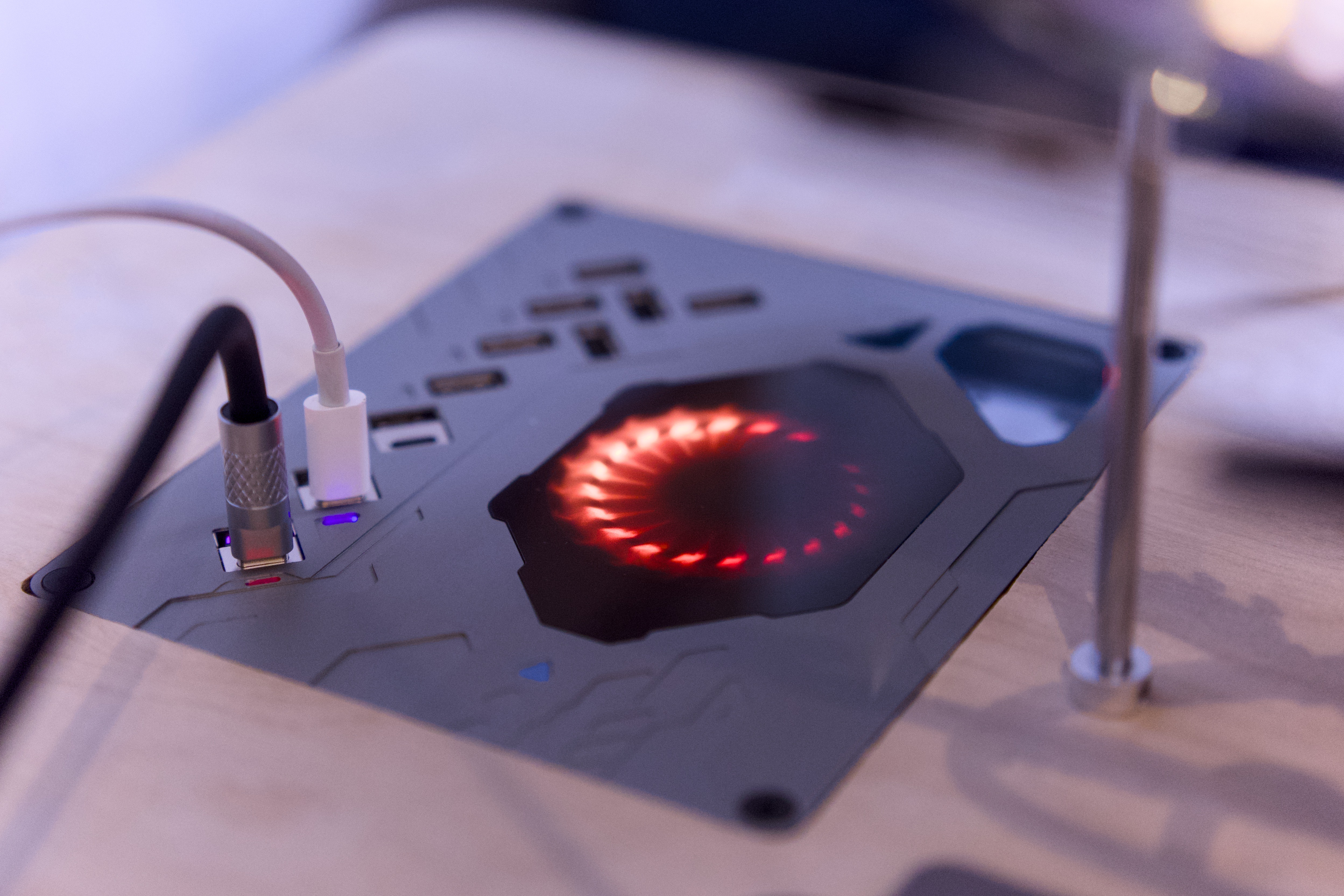
product image (above) This desktop power
station , embedded in the desktop,
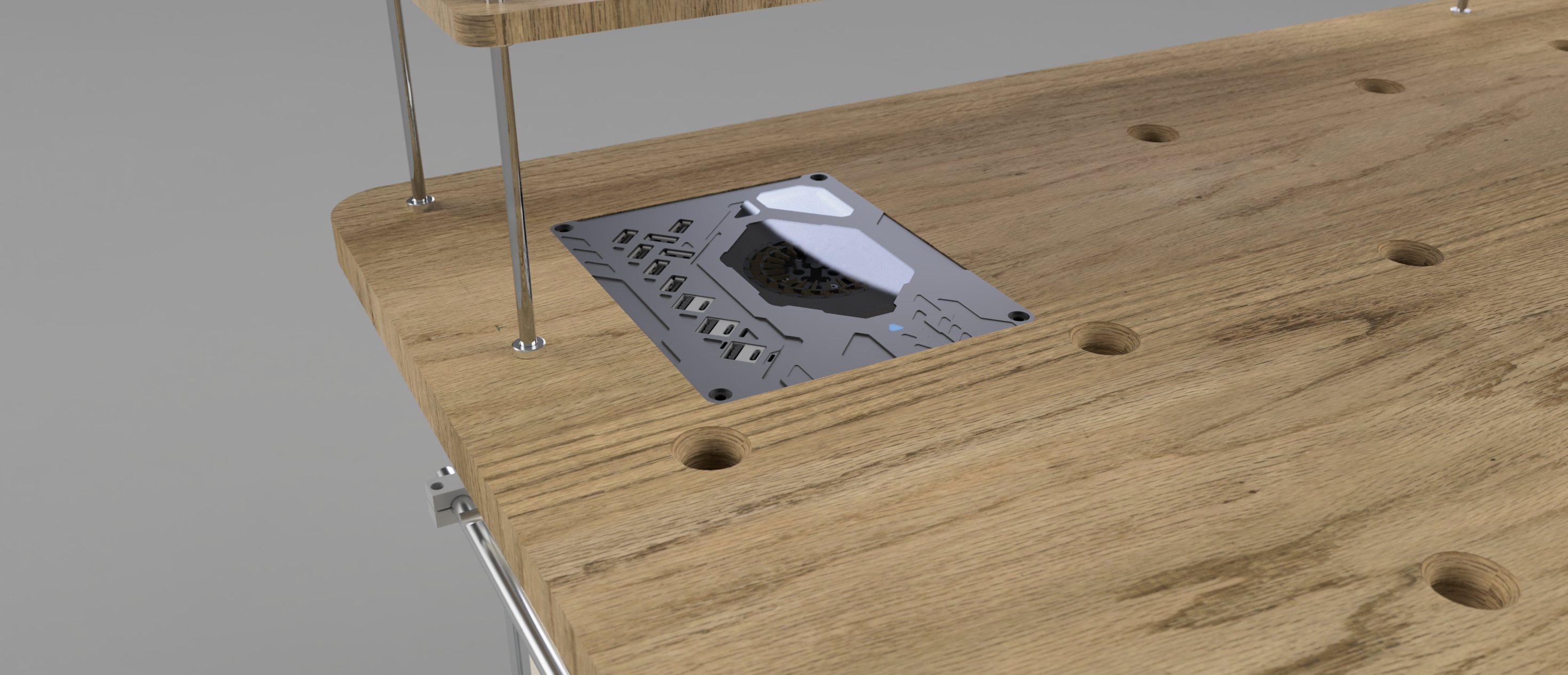
provides high-power fast charging for USB devices and supports wireless charging for mobile phones.
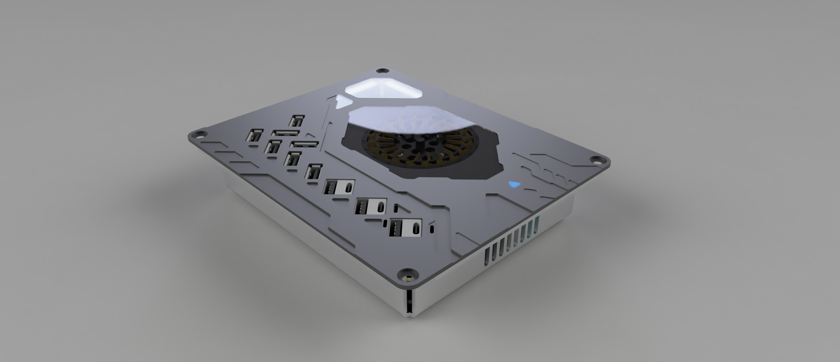
It utilizes JLC PCB, panel, CNC, 3D printing, and sheet metal work to create a 13-port 245W USB/TYPE-C workbench power station + wireless charging station
.

The PCB
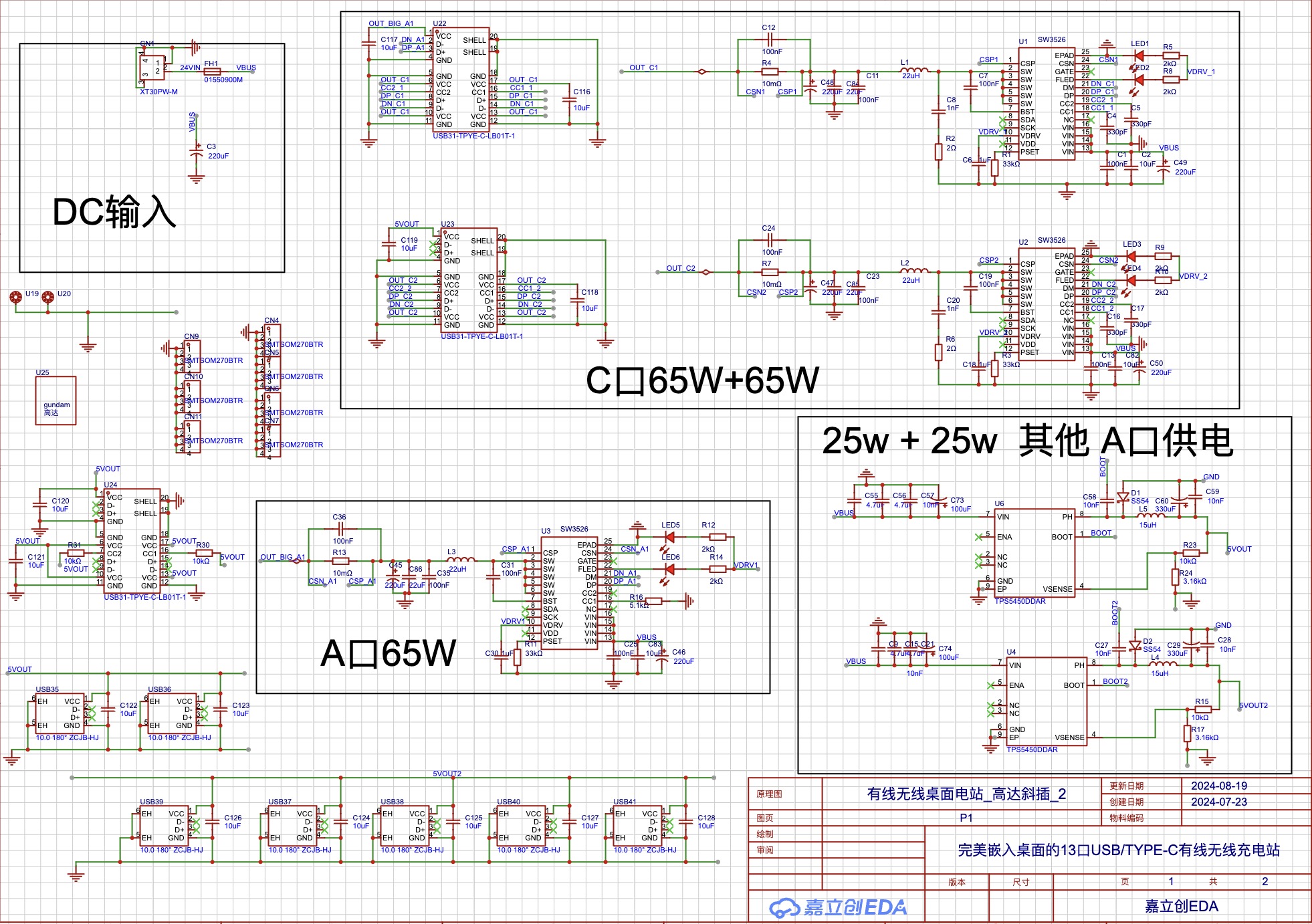
uses three SW3526 chips, corresponding to two Type-C and one Type-A ports.
The other Type-A ports are powered by a TPS5450,
and the remaining Type-C port is a fixed 15W port powered by one of the TPS5450 chips.
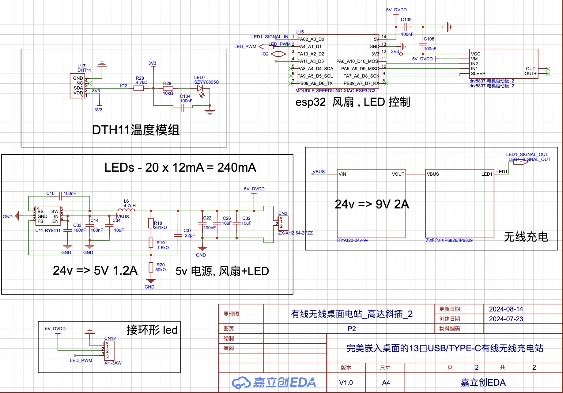
The ESP32 microcontroller uses ESPHOME low-code to control the fan based on temperature and the LED ring animation based on the on/off status of the wireless charging module's LED indicator.

The board is modified from DongDuZhiLang's desktop charging station (2C 65W 1A 65W 10A 5W).
Previously, I only knew how to use ESP32 and Arduino, and I couldn't draw circuits. I've only been learning for a few months, previously using JLC EDA... I made one or two small, simple sensor boards, which is considered my EDA entry point. This was my first time making such a complex board, and at first, I thought I couldn't possibly fix it, given how complicated it was. However, I spent time slowly understanding the entire circuit and learned how to use and connect the SW3526 and the TPS5450DDAR. It's still very basic, so please correct me if I'm wrong.
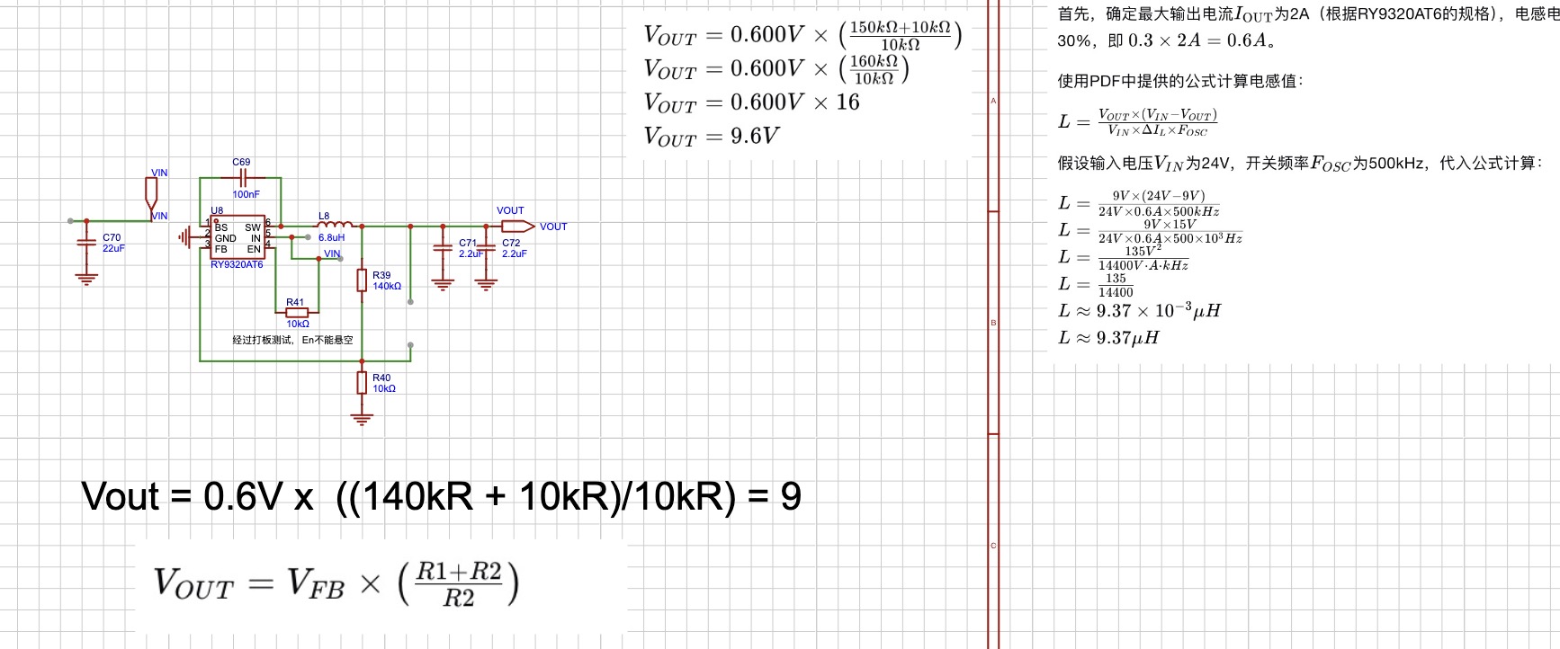
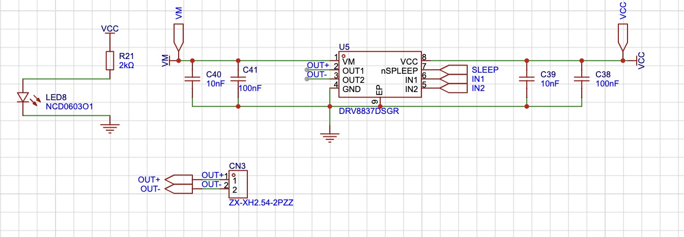
The board is based on the teacher's original design, but all the USB connectors were soldered to the back facing upwards because I wanted to embed it flush with my desktop. I added a temperature sensor, an ESP32-C3, and a fan for active cooling. A cheaper solution could have been used for this, but I chose this one because I had many spare ESP32s. I learned ("copied") a 24V to 5V RY8411 circuit to power the fan, and also checked if a drv8837 could be used to drive the fan (verified).
I added a 12A fuse.
I used ESPHome to obtain DTH11. Active heat dissipation is implemented for the temperature.
A heatsink mounting location was also designed. An
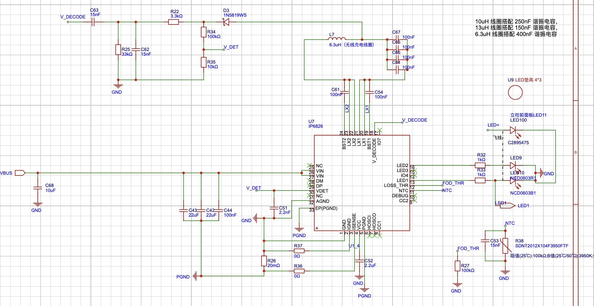
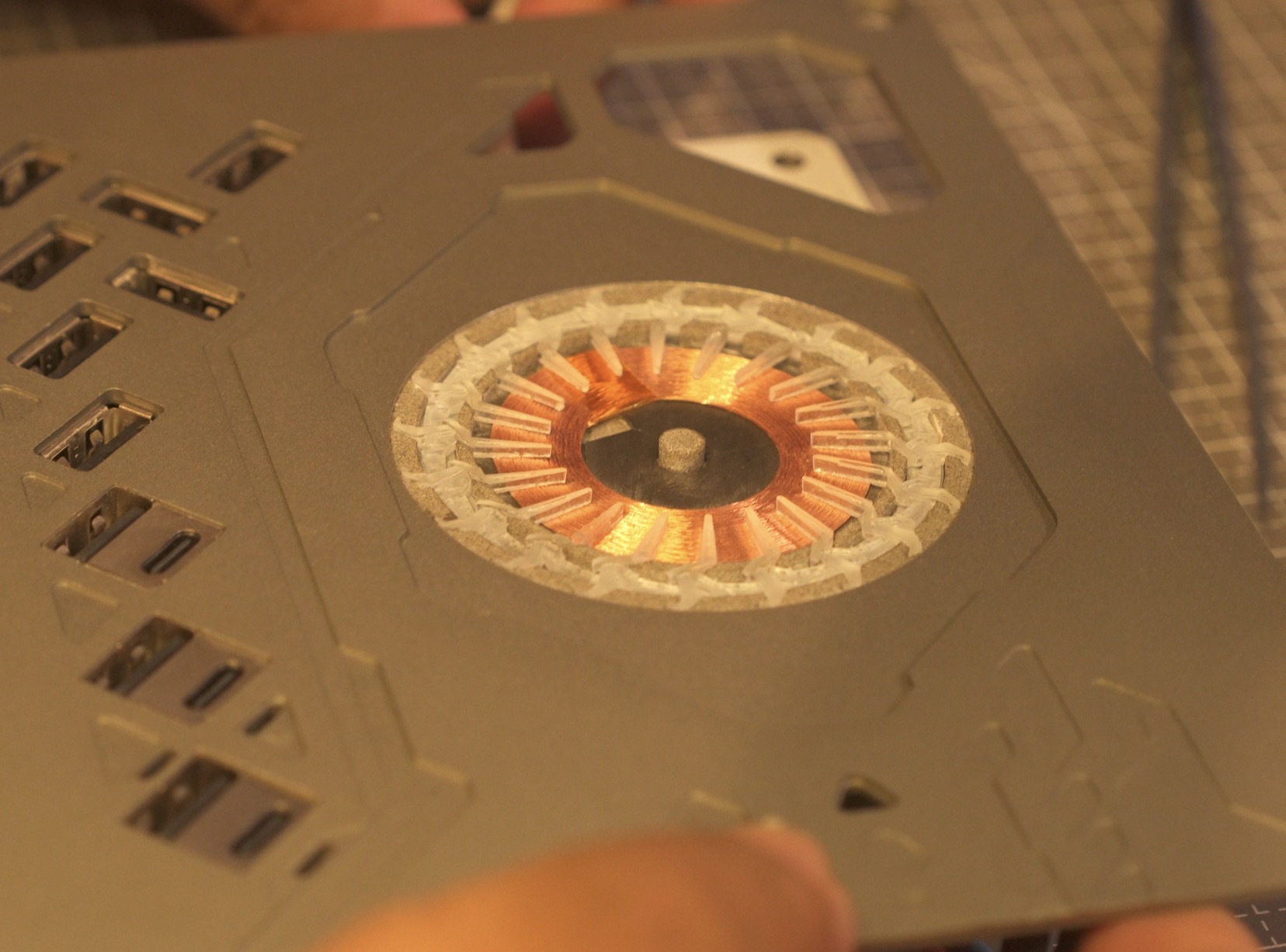
IP6829 wireless charging module was added. The coil specifications can be found by searching "ultra-thin 43.5mm with adhesive backing".

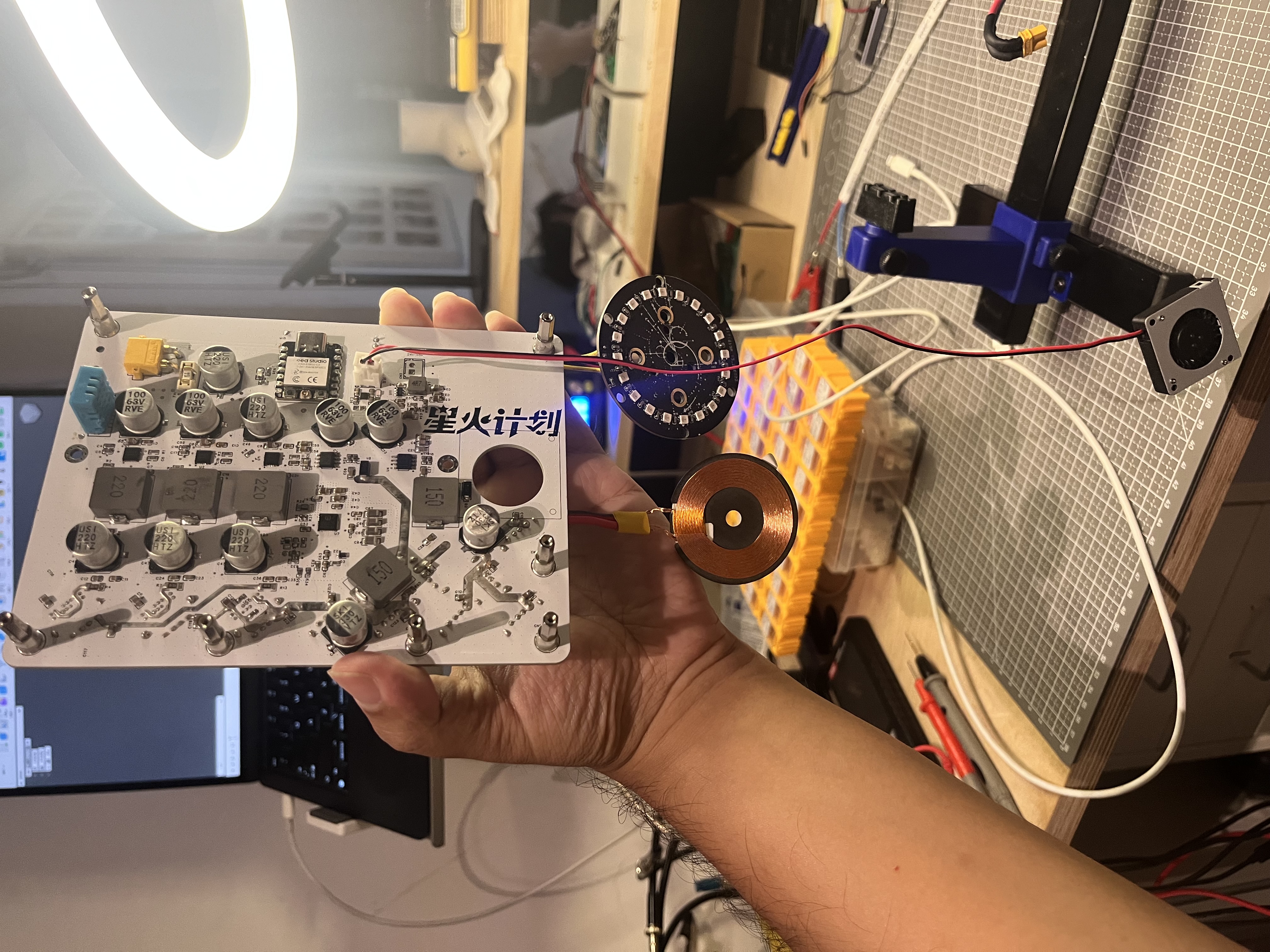
This is a picture of the completed motherboard. During soldering, it was found that the solder pile area and the adjacent pads were too close, and the capacitors on the circuit were easily attracted, causing the 5V-GND to be directly connected. This needs to be noted. The PCB has been slightly adjusted.
Soldering precautions:
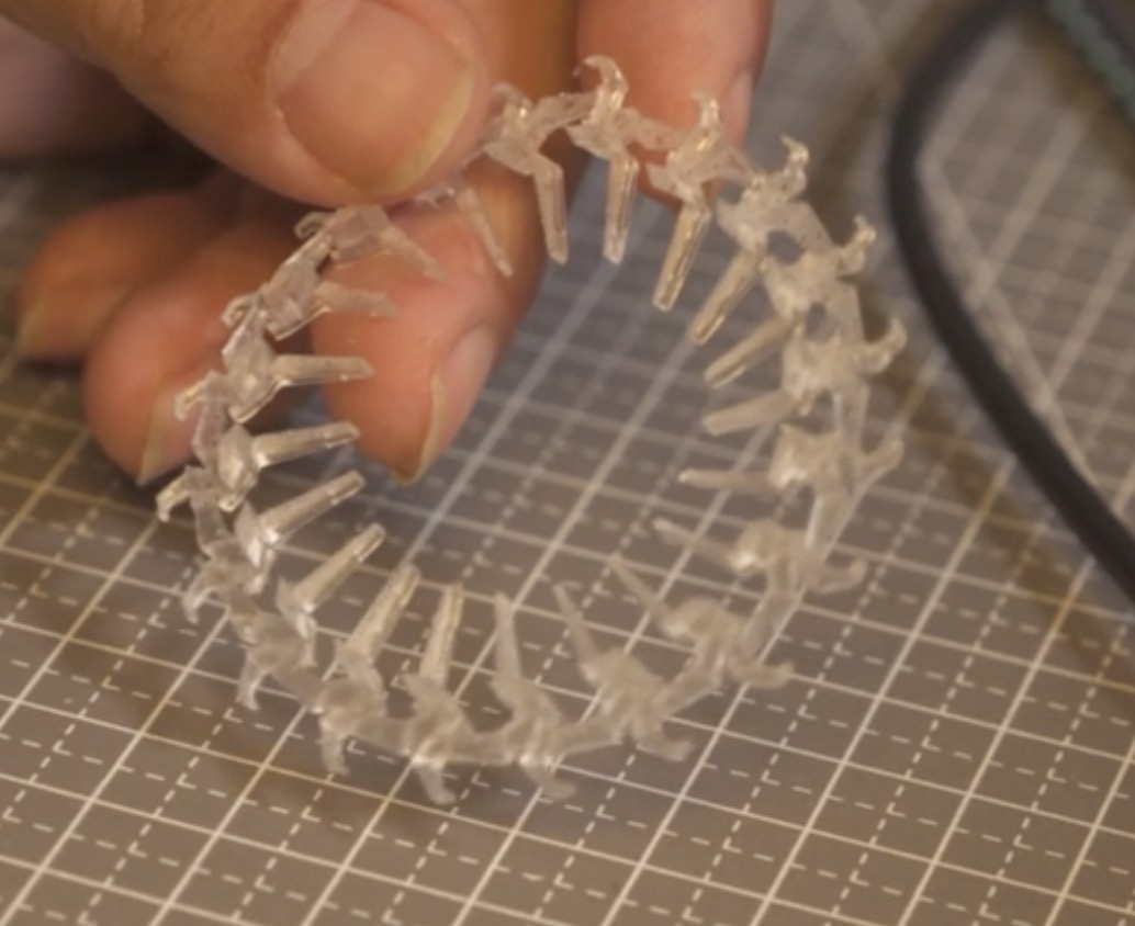
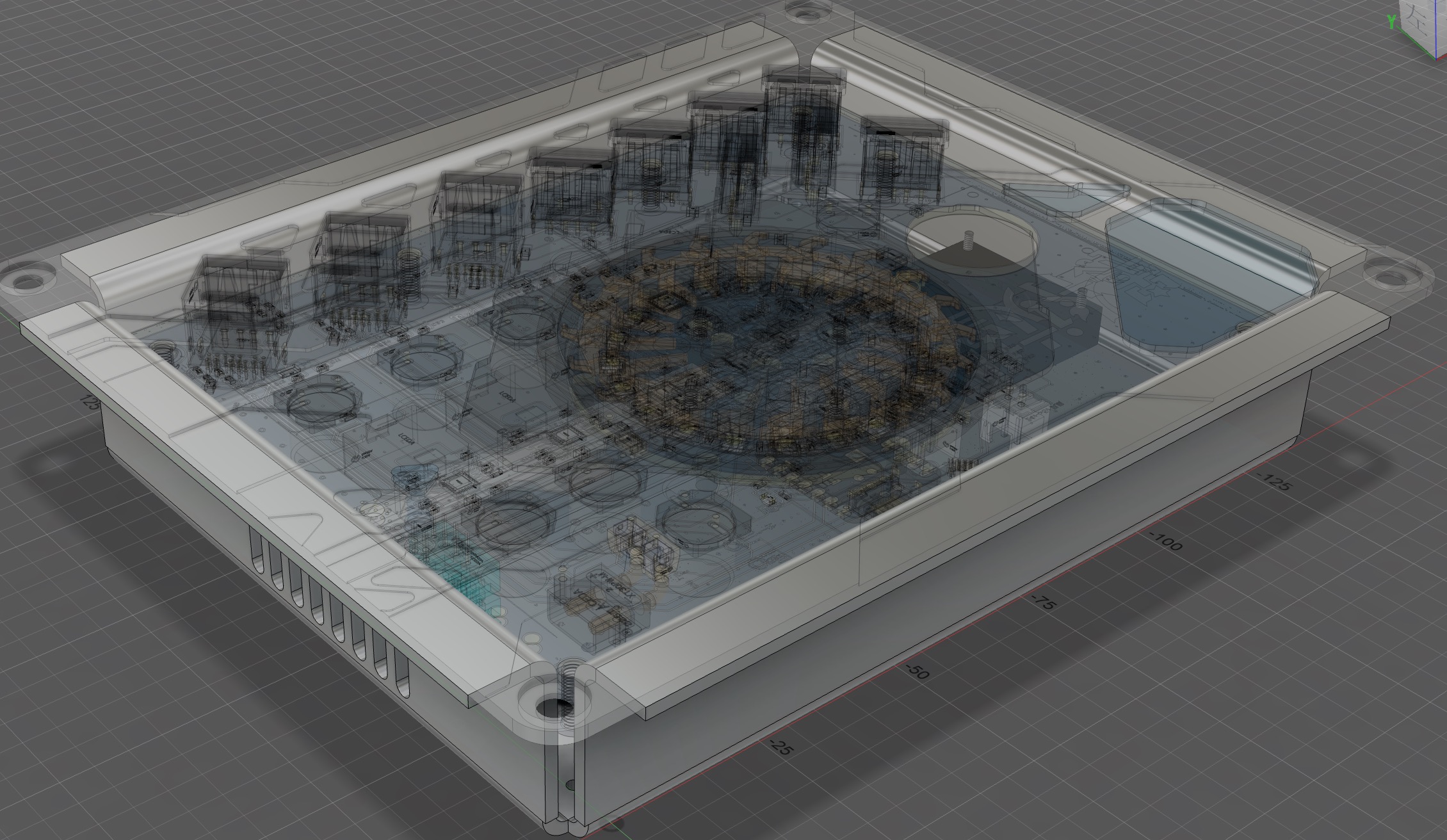
SW3526 and other chips that indicate static electricity. Never use an ungrounded soldering iron to solder the wireless charger. The wireless charger is powered by 9V. Testing showed that 12V does not work, only 9V
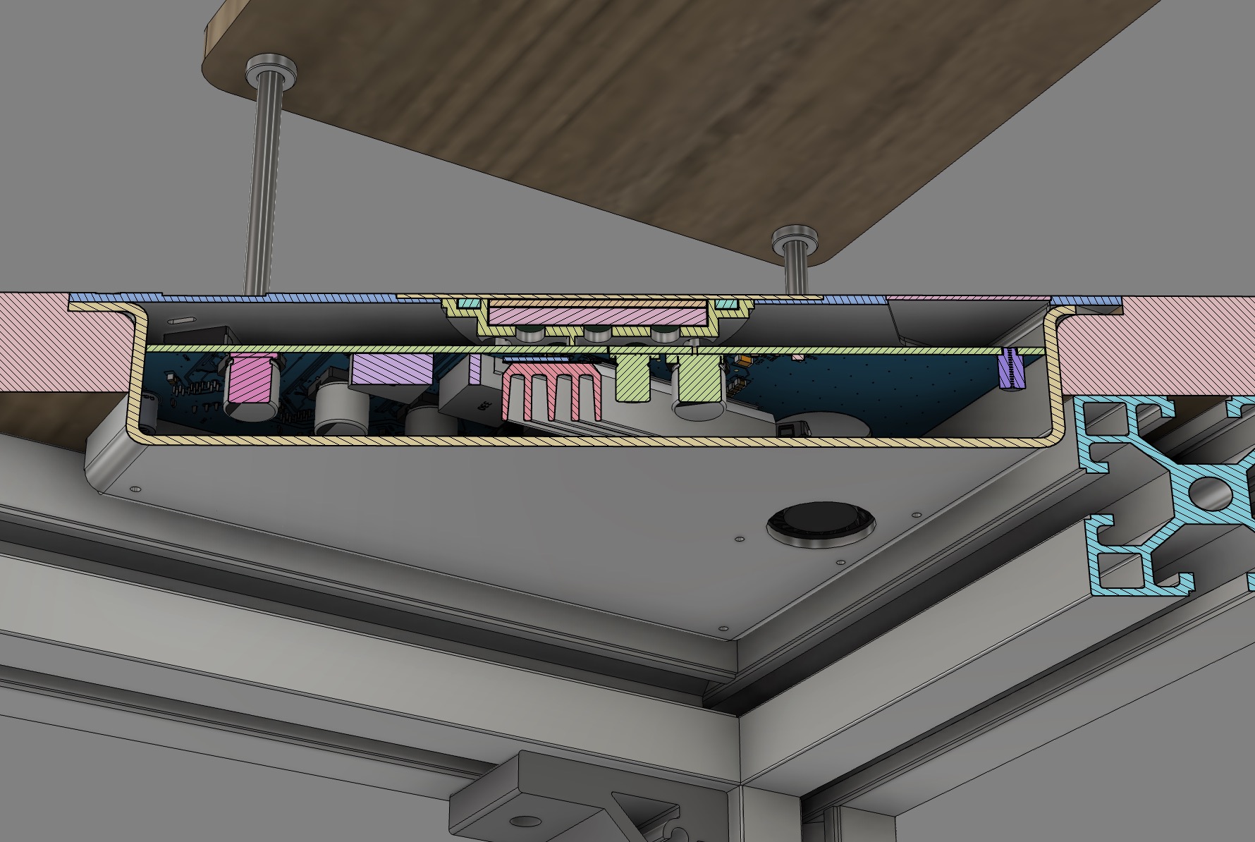
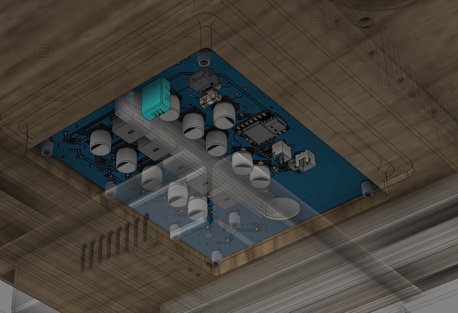
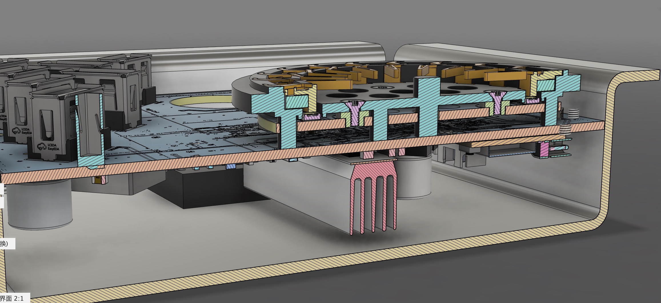
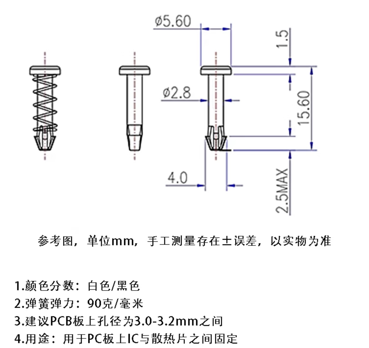
wireless charging. My coil is 6.3uH. The bracket structure is shown in the picture above. The blue part is the 3D printed bracket, which is fixed by the top cover plate, but it is not tightly connected to the motherboard. It is fixed to the LED ring board below with a countersunk M2x4. The LED ring board below the bracket is controlled by ESPHOME and is a WS2812 LED. The code is in the attachment. The colors and flowing light effects were adjusted. The front and back light guide rings and the base are combined. The fan control is DRV8837. Here, it's just a simple PWM control of the IN1's on/off state. The code is all on ESPhome. ESPhome is very simple once you get the hang of it. Spend time understanding its module concepts, and you'll be able to do a lot without writing code (I did write some code for a better flowing light rotation effect for the LED...). The actual shell (above) is made of 201 stainless steel with 120 sandblasting, and the texture is very good, but it leaves fingerprints when touched (facepalm) . The bottom box of the shell is sheet metal. I found an SMTSOM270BTR copper pillar on EDA. The 3D size can be previewed in EDA, which is quite good. However, the model with L=7mm is 3mm, which is incorrect. It needs to be changed after importing into Fusion. The board actually needs to be 17mm. Here, I also used 10mm hexagonal copper pillars bought on Taobao to connect the four corner screw holes of the cover. It can be fixed with self-tapping screws or used as a decoration. I used it for decoration. The sheet metal shell is bent excessively inward by about 0.5-1mm on the two long sides, and the PCB can't fit because the shell is stainless steel...2mm, it's really hard to bend... ($%^& Not budge...%^&* ). I chose to grind the PCB, and after grinding for a long time, I finally put it in... Temperature measurement, heat dissipation. The heat dissipation is this size, custom-cut 110mm. Spring rivets, 15.6mm type, 3mm hole drilled in the heatsink. Actually, a surface-mount PCB temperature sensor could also be used for temperature measurement (more suitable), but I haven't used it before. DHT is used more often, ESPHome supports it, and I don't want to change it. After installing ESPHome from Baidu, connect the computer to the ESP32C3 via USB, modify the part related to Wi-Fi and password in usbpower.yaml, and enter esphome run usbpower.yaml After flashing the firmware to the ESP32C3, enter the address usb_power_node.local in your browser to access the web configuration page. Generally, you don't need to change these parameters: power supply, power delivery, and assembly.


Theoretical maximum power: 65*3+25+25+6+18 = 269W.
I used a Mingwei power supply, suspended under the desktop.
The desktop is made of marine board. I will also upload the desktop model and schematics.
2024.8.8
PCB adjustments were made. Wireless charging is integrated into the motherboard, and an LED light ring PCB was added.
In addition to the four corner supports, three more pillars were added to prevent the PCB from deforming under pressure when plugging in the USB
. Supports were added around the USB port to prevent deformation under pressure. Three corresponding screw holes were added to the casing .
2024.8.17
PCB soldering completed. Functional testing showed that it was normal except for a continuous restart when charging a laptop at 20V. Troubleshooting .
2024.8.18
The restart problem was solved. The reason was insufficient input voltage (24V). I adjusted it to 25.6-26V, which worked. During this process, I replaced three 10uF 25V Vin capacitors in the SW3526 section with 10uF 50V capacitors (circuit diagram has been changed here).
August 21, 2024:
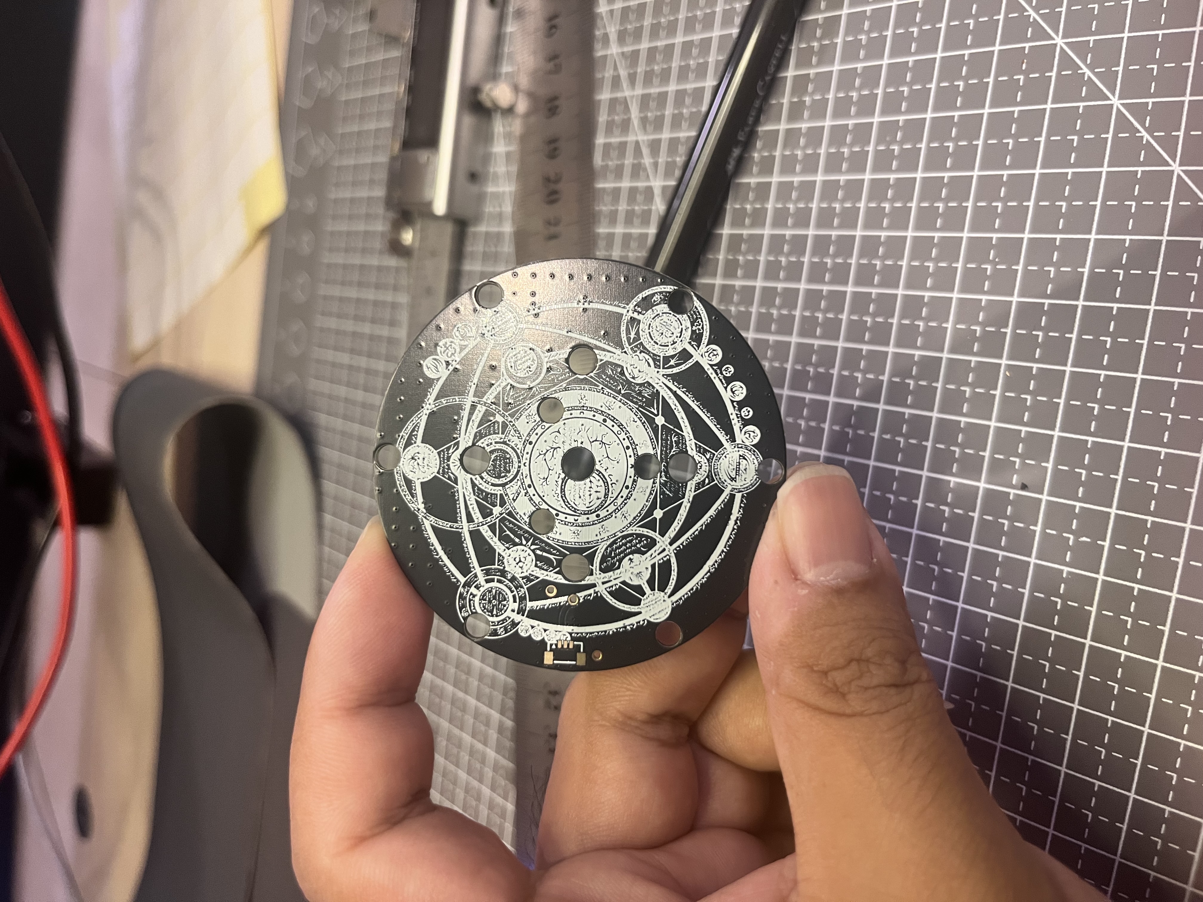
Added a deep space gray matte visual effect. Whether to go for matte or glossy is still undecided... worried that matte won't be bright enough.
August 27, 2024:
The wireless charging coil power cable needs to pass through the LED ring panel; no holes were cut. The PCB has been modified and added, but I didn't re-make the board; I drilled the holes directly.
September 2, 2024:
Covered the circuit board and added a real-object photo.
The matte anodized finish is indeed not very bright... I want to see the glossy effect when I have the chance.
Adjusted the width of the circuit board PCB because the width of the sheet metal casing was 0.5-1mm too large, and the PCB couldn't fit. I sanded the PCB, but now I've reduced the PCB width by 0.8mm. It should be fine for a re-print.


 京公网安备 11010802033920号

 1201M1S3V3QD1


