 Then, prepare the enameled wire and measure its diameter with calipers. This demonstration uses two 0.56mm
  single-strand wires of the same length. Tie a knot, the length of which depends on the number of turns you'll be winding; remember to leave some slack. Secure
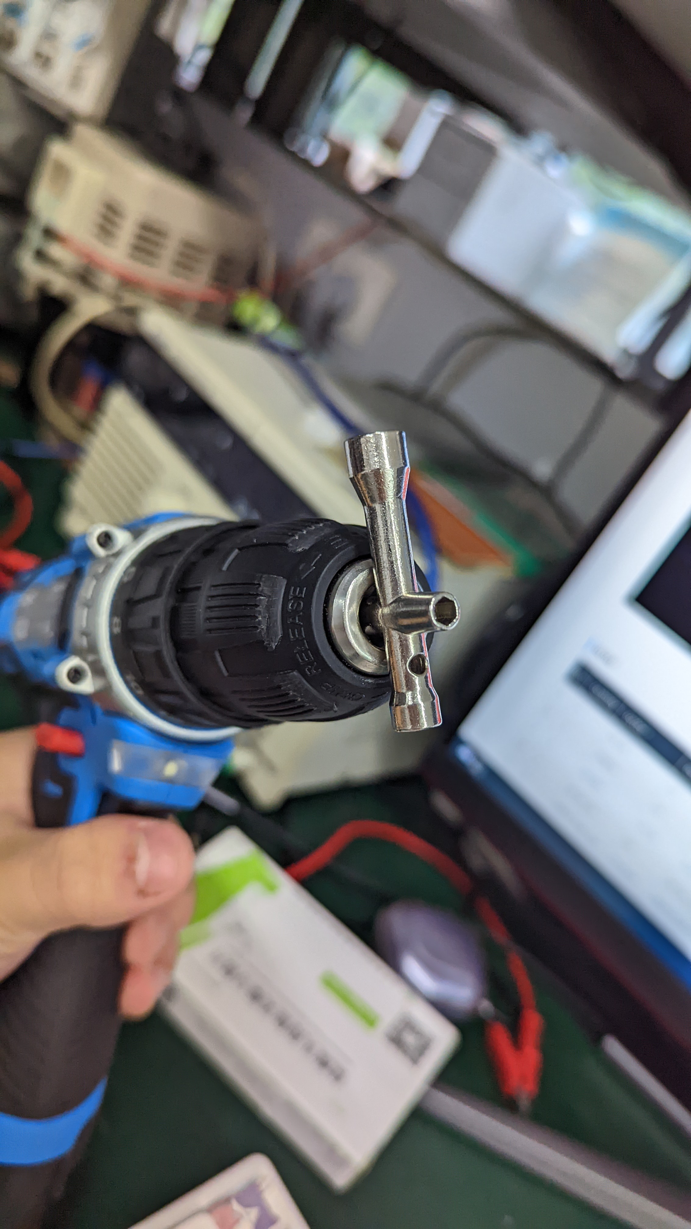
 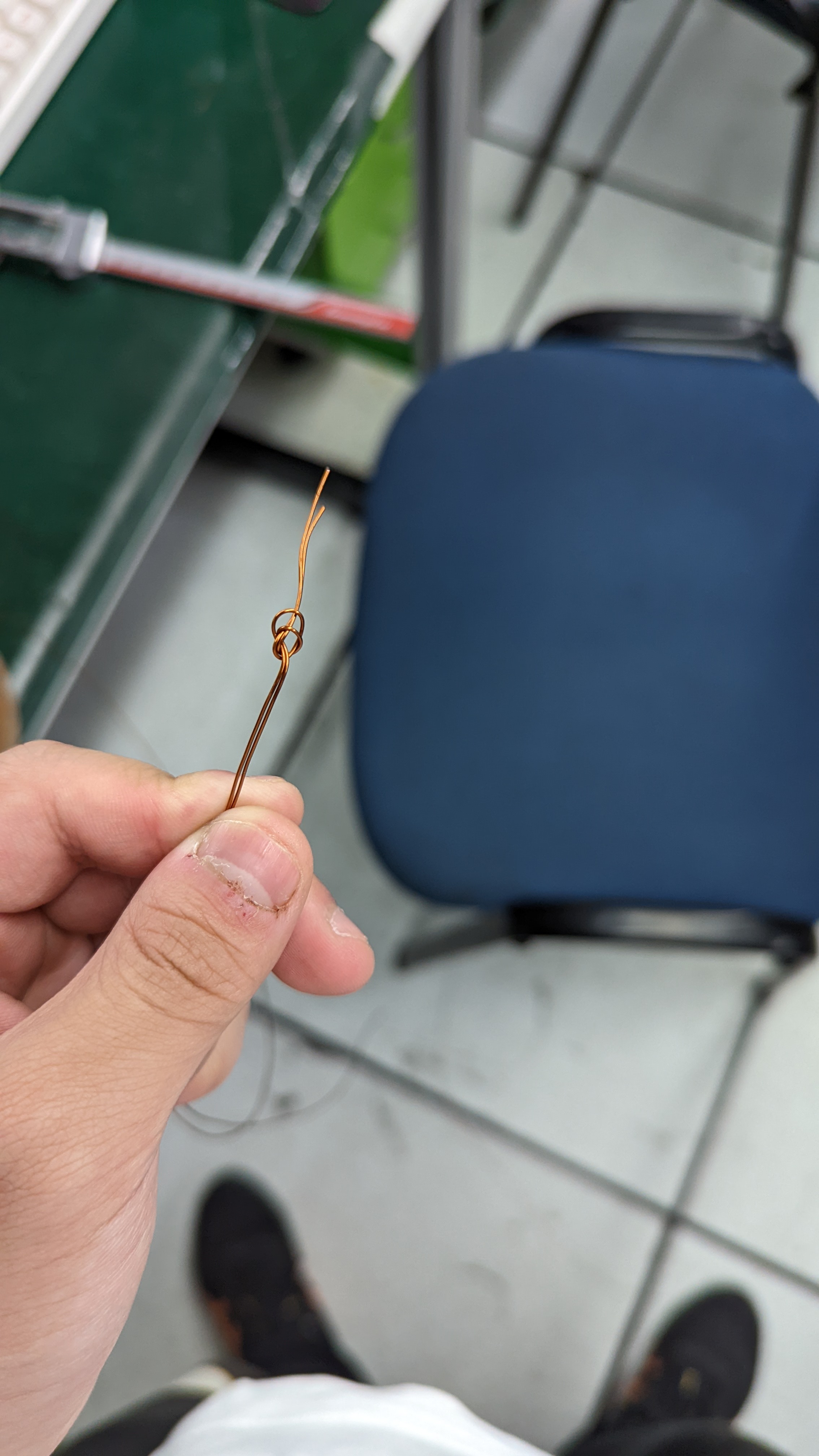 the knotted end to a door handle, and fix the other end to either side of the drill bit's hook.
  Then, as shown in the attached video, turn the drill. The two strands will be wound together. Pay attention to the tightness of the double strands and the winding arrangement. If there are too many strands, the tension will be too high, making it difficult to wind. Here, 10 strands of 0.57mm enameled wire are used, resulting in 5 two-strand 0.57mm wires and 3 two-strand 0.46mm wires.
  After preparing the double-strand wire, the next step is to wind the primary winding. To improve the coil's induction effect, the primary winding is divided into two layers: the bottom layer is pins 1-2, and the top layer is pins 2-3. At this point, pay attention to the issue of the same-name terminals. A rule of thumb is: for coils wound in the same direction, the input terminals are the same-name terminals.
 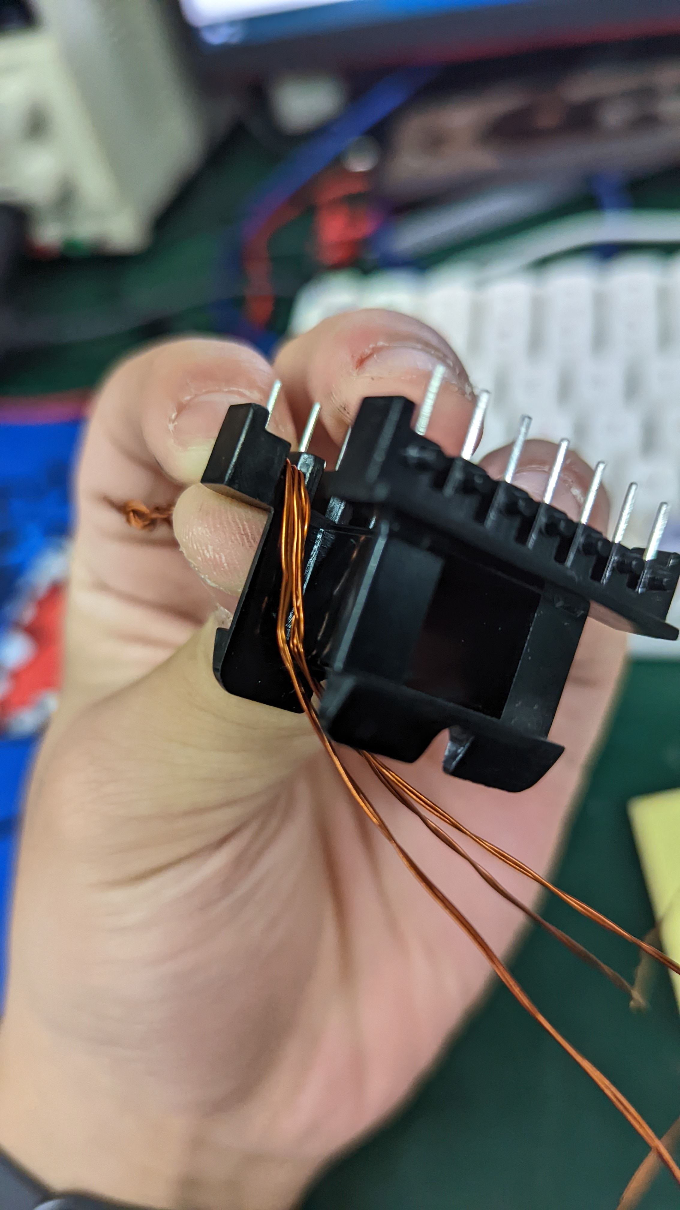 Then begin winding. When the bobbin can't be wound any more times, slightly fix it, wrap it with Mylar tape, and then extend it in the opposite direction and continue winding. I wound 10 turns in the first layer. After winding, as shown in the picture below, remember to wrap it with Mylar tape (I forgot to take a picture of this, but there's a guide on how to wrap Mylar tape in the attachment, and you can probably imagine it after seeing this picture).
  Bend the multi-strand wire slightly, extend it towards pin 2, and wrap another layer of Mylar tape.
 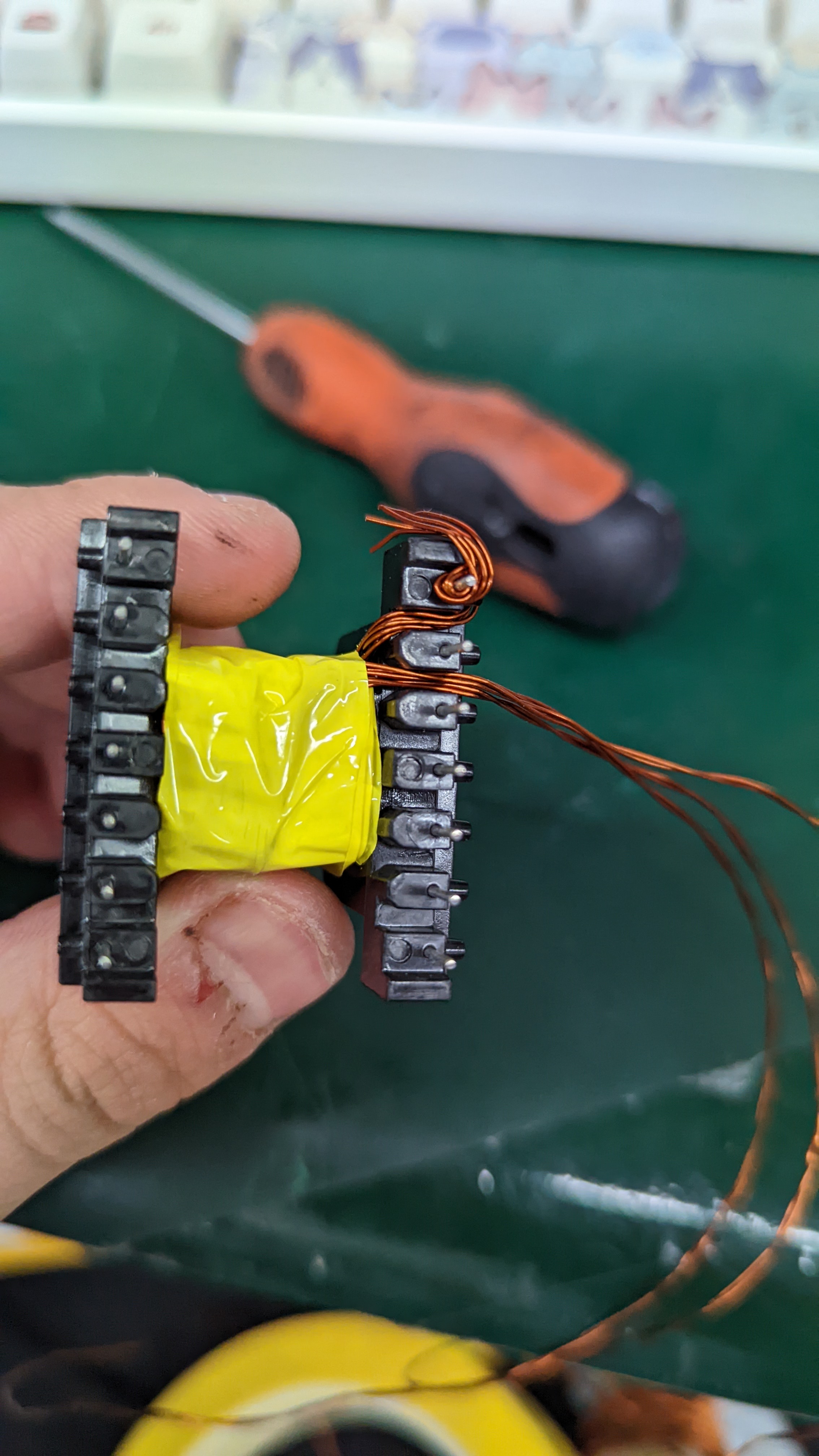 Then cut the multi-strand wire, remembering to leave a little length, and put it in a sleeve (I used heat shrink tubing here). Scrape off the enamel from the enameled wire. Here's a crucial point: the enameled wire must be scraped clean in strands. Don't cut corners; ensure every copper wire is thoroughly scraped clean. After scraping, tin each strand to ensure it's completely clean, and also tin the pins for easier soldering.
 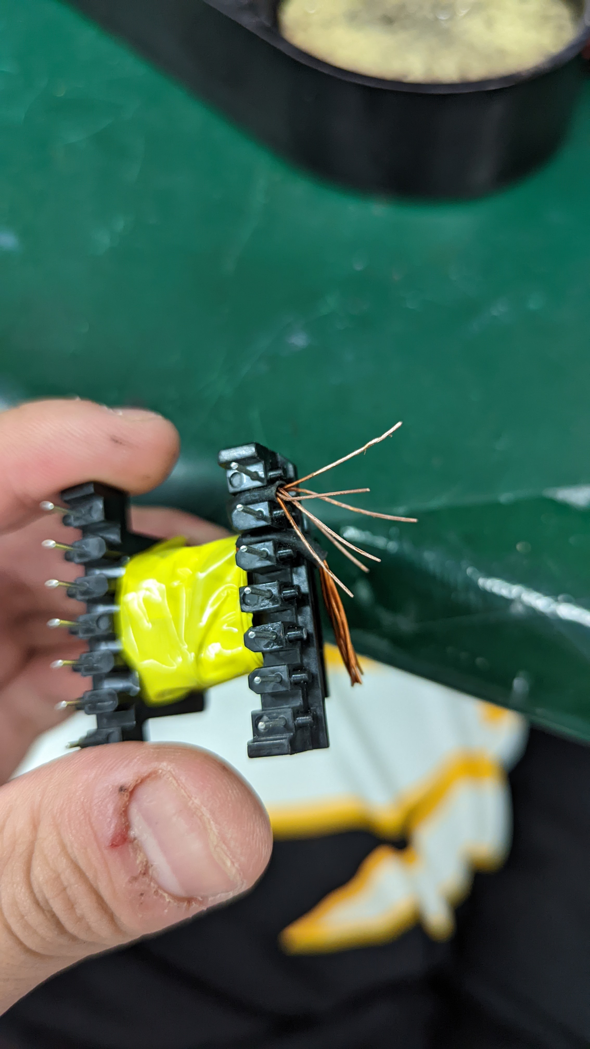 Wind multiple strands of wire onto the pins and solder them in. Make sure the soldering is secure and avoid any gaps.
  Repeat this process for the other pin. Once this is done, the first layer of the primary winding is complete. Next, wind the auxiliary winding. Since the auxiliary winding only requires one strand of enameled wire and has very few turns, wind it evenly. Pay close attention to the same-name terminals! After
 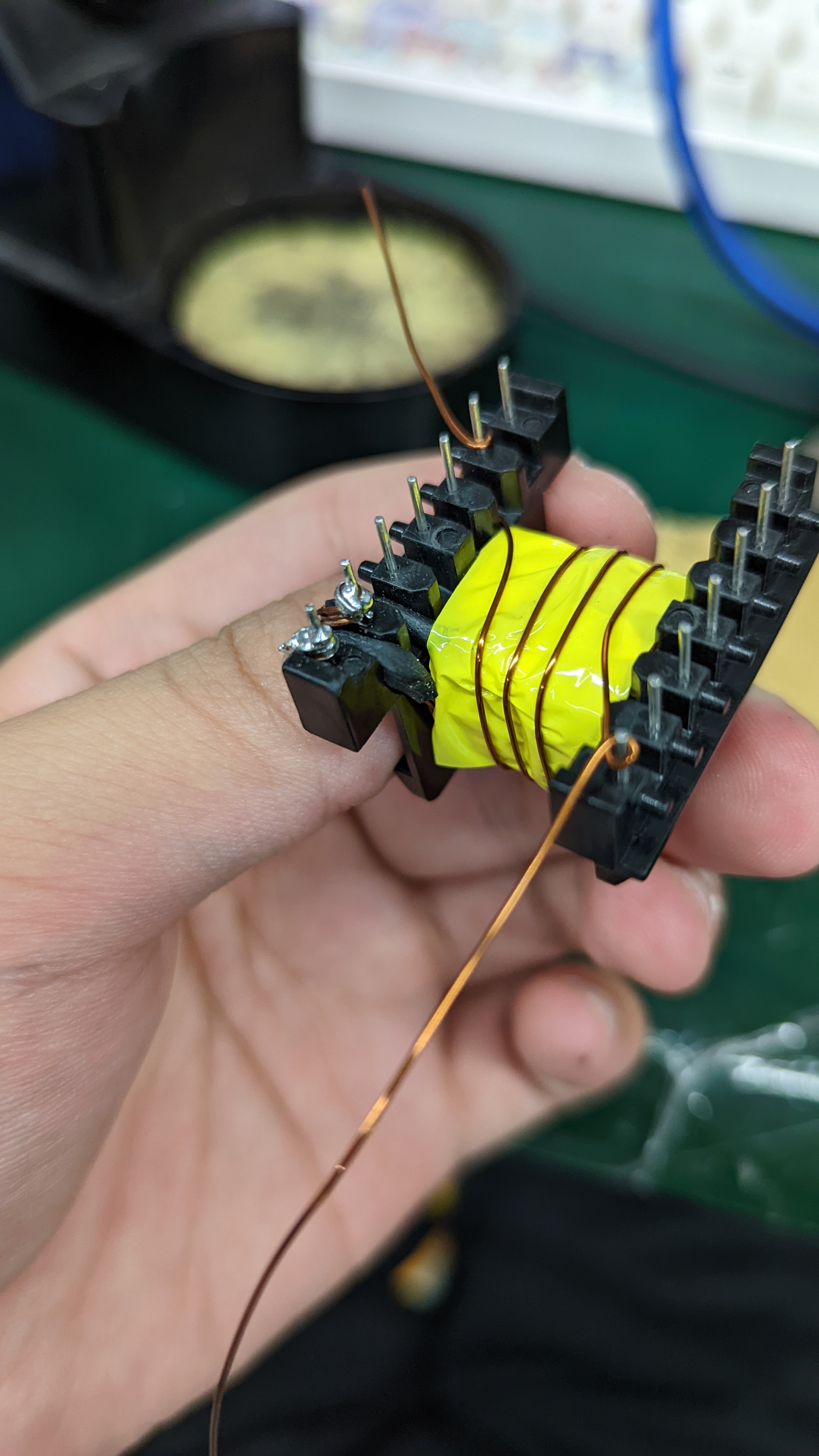 winding as shown in the diagram, process the pins using the same method. Next, wind the secondary winding. Because the secondary winding has many strands, use two pins as one: 6 strands for pin 8 and 4 strands for pin 9. Wind it using the same method as before, again paying close attention to the same-name terminals.
 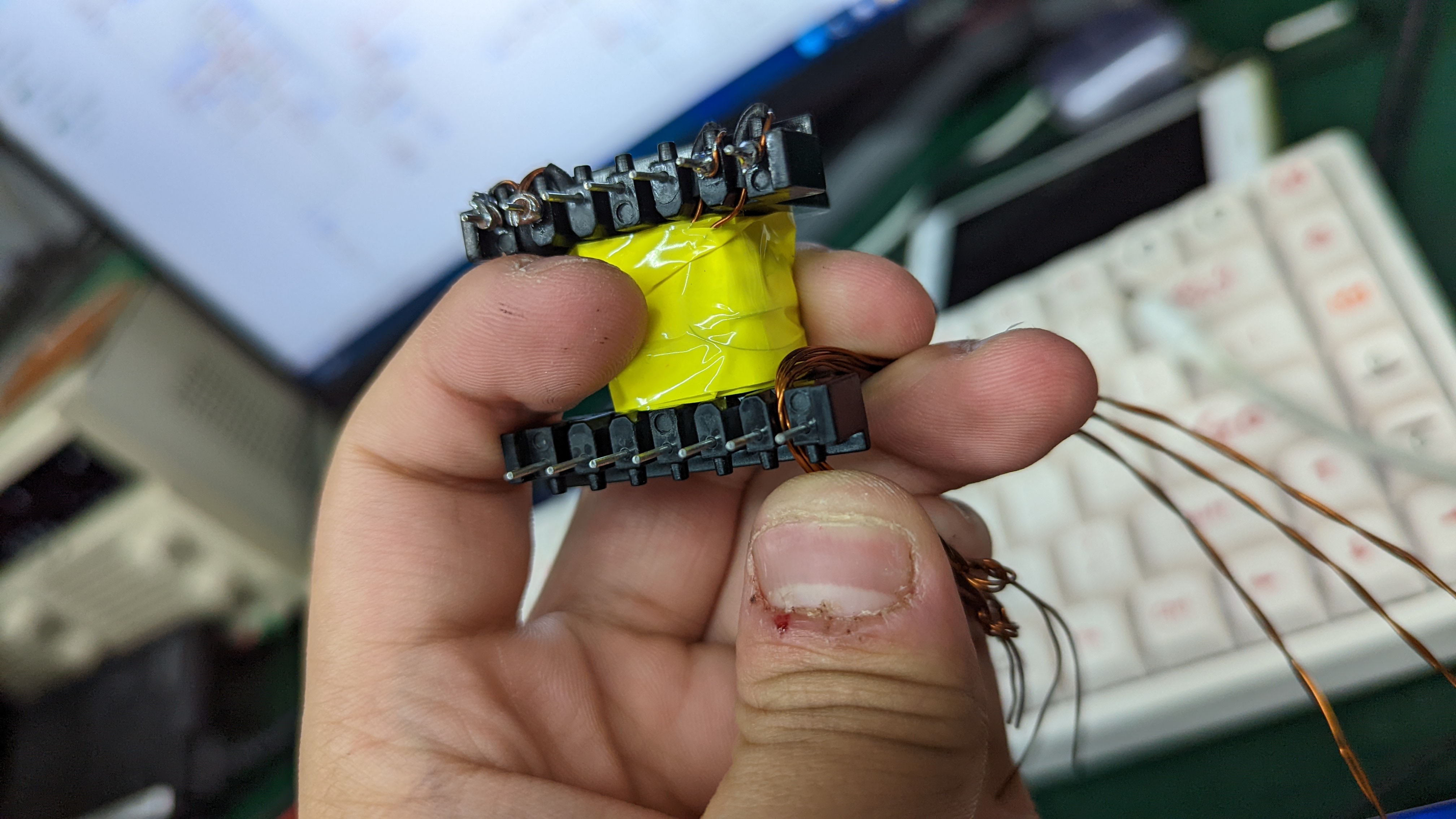 Then wind the second layer of the primary winding, using the same method as before, so I won't elaborate further. After winding and processing the pins, it should look like the image below.
 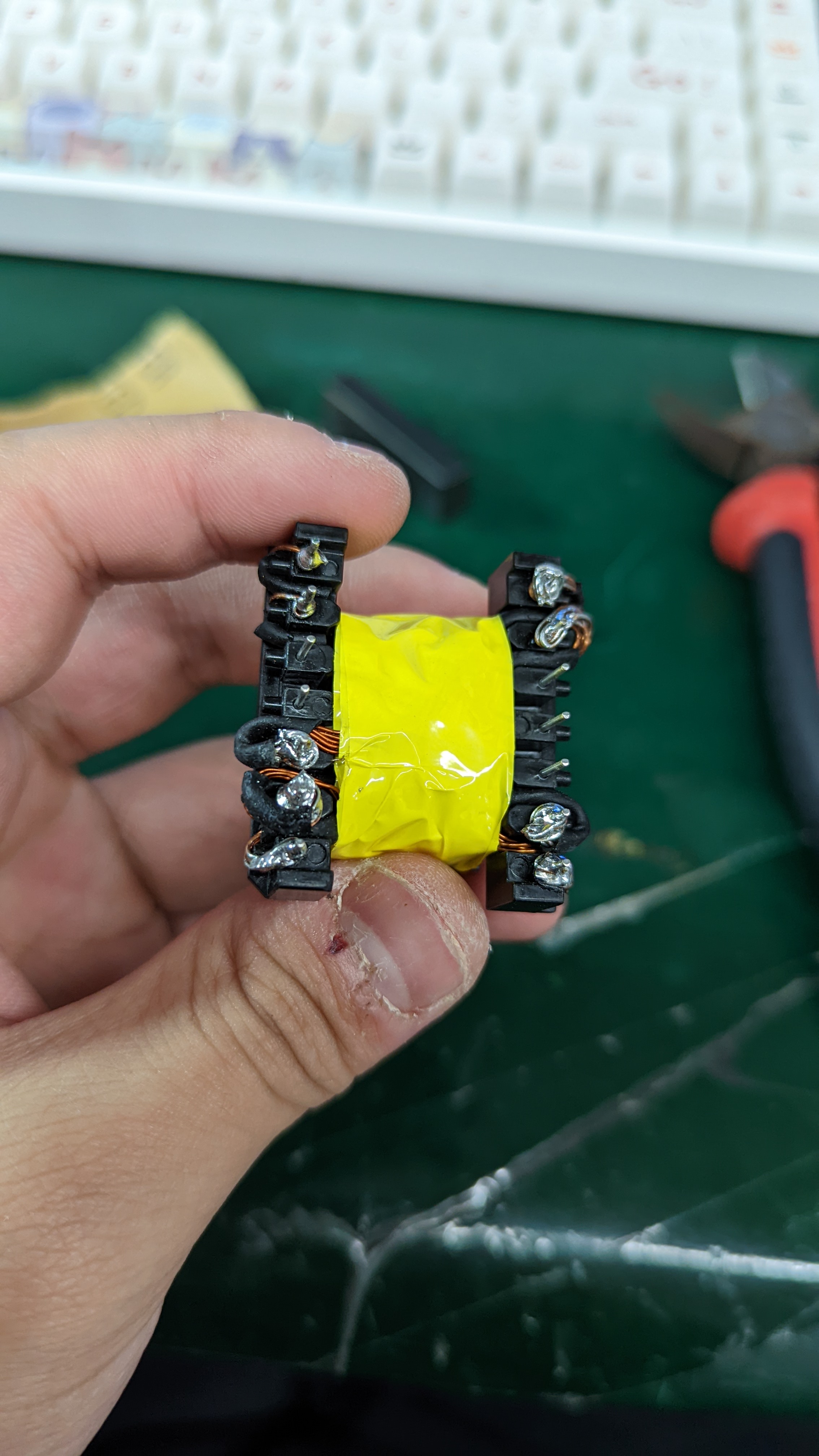 Then, take out the magnetic core, insert it, and secure it together. Wrap it with Mylar tape and test.
  After testing the transformer primary winding with a bridge circuit, you'll find the inductance is extremely high, indicating this processing is incorrect. Therefore, we need to add some space between the magnetic cores using Mylar tape. Here, I've attached it to the stick-like end, as shown in the image below. Next,
 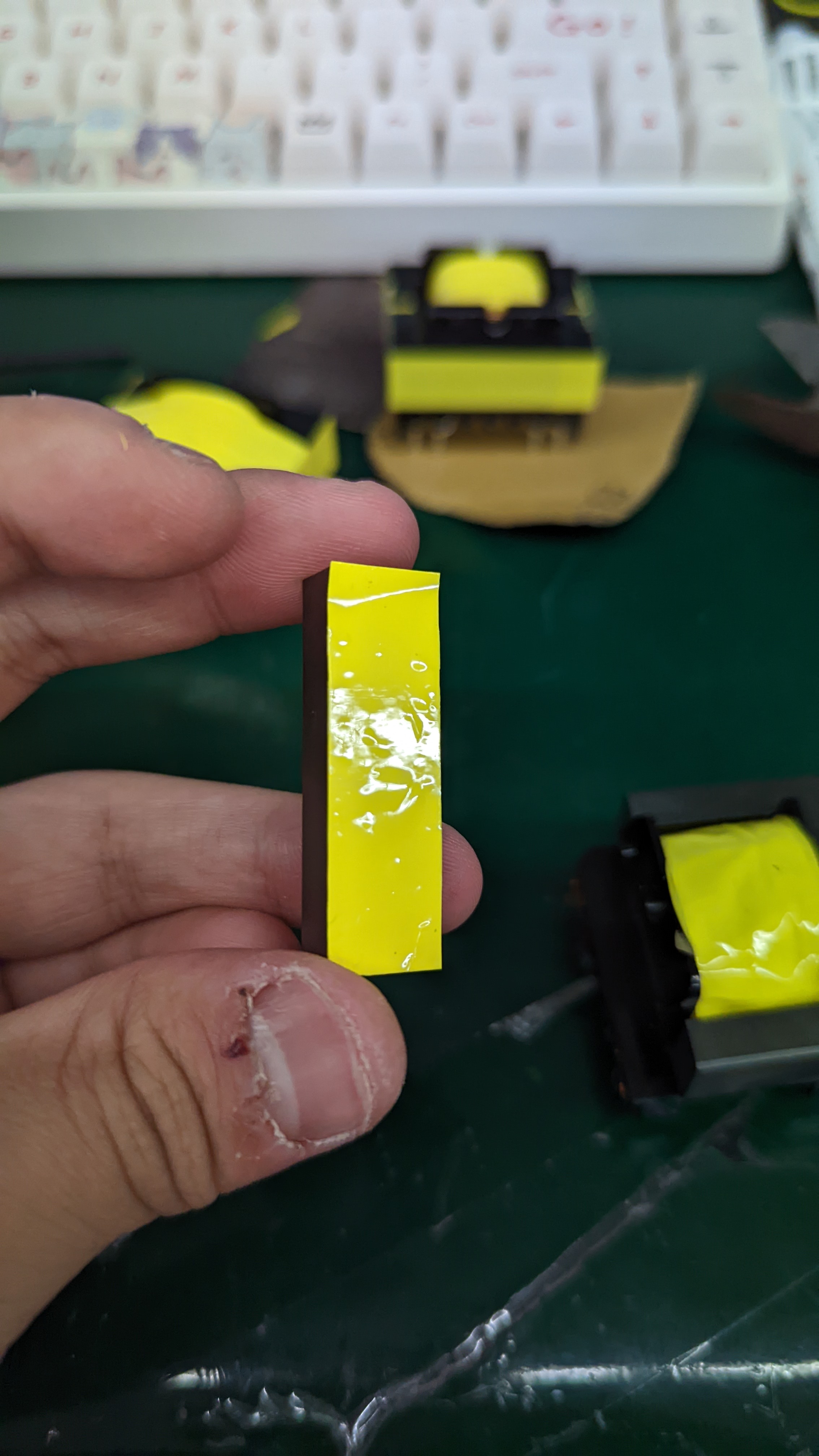 adjust the number of Mylar tape pads, adding or removing them little by little until the inductance matches the calculation.
 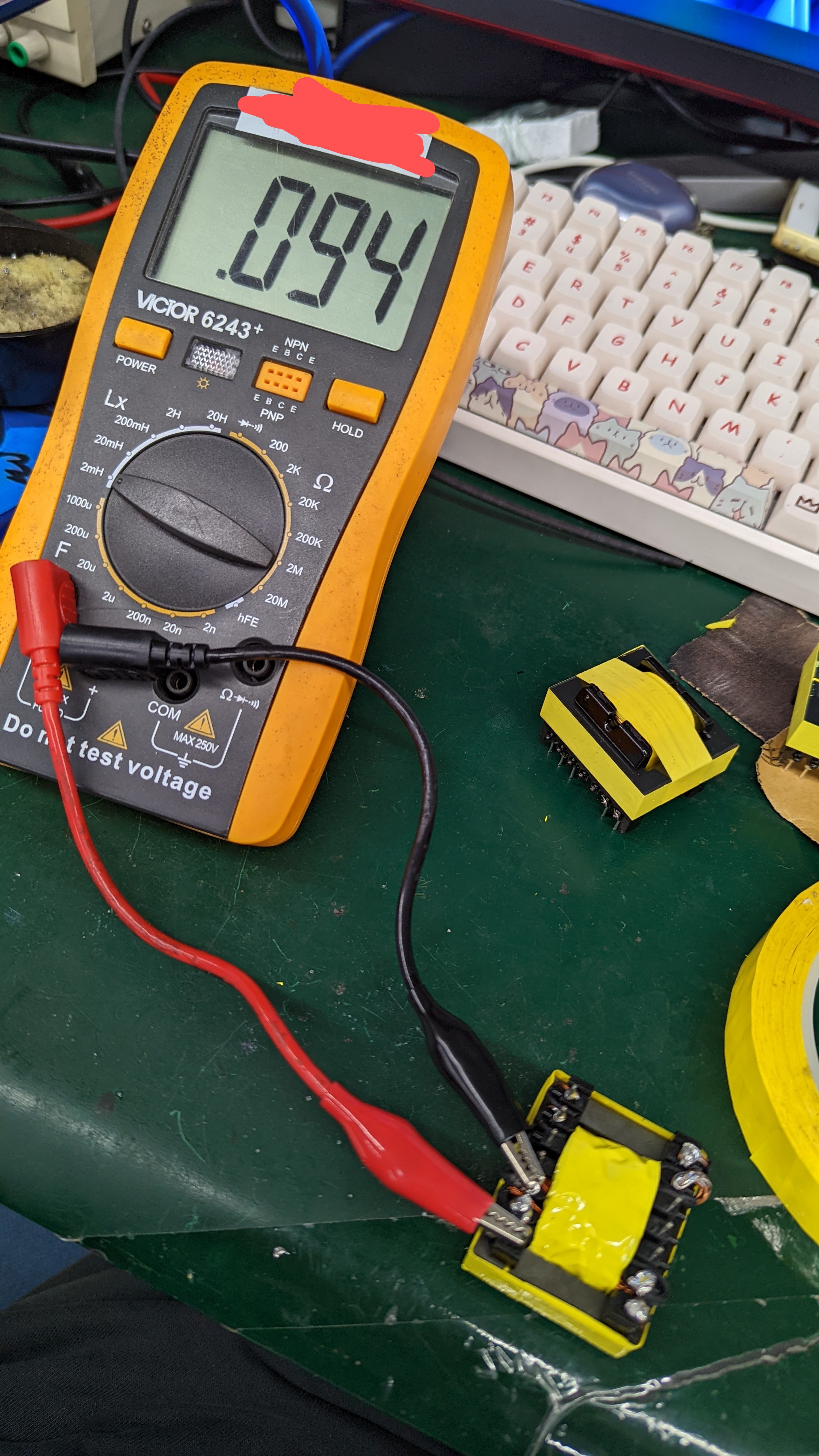 Then, apply some glue between the magnetic cores to secure them firmly, and wrap it with Mylar tape again. The winding is now complete. In summary,
All reference designs on this site are sourced from major semiconductor manufacturers or collected online for learning and research. The copyright belongs to the semiconductor manufacturer or the original author. If you believe that the reference design of this site infringes upon your relevant rights and interests, please send us a rights notice. As a neutral platform service provider, we will take measures to delete the relevant content in accordance with relevant laws after receiving the relevant notice from the rights holder. Please send relevant notifications to email: bbs_service@eeworld.com.cn.
It is your responsibility to test the circuit yourself and determine its suitability for you. EEWorld will not be liable for direct, indirect, special, incidental, consequential or punitive damages arising from any cause or anything connected to any reference design used.
Supported by EEWorld Datasheet
EEWorld
subscription
account

EEWorld
service
account

Automotive
development
community

Robot
development
community

About Us Customer Service Contact Information Datasheet Sitemap LatestNews


Room 1530, 15th Floor, Building B,
No.18 Zhongguancun Street,
Haidian District,
Beijing, Postal Code: 100190
China
Telephone: 008610 8235 0740
 京公网安备 11010802033920号

 OR2C15A-4M208


