Project Description: This project
involves creating a mini-load that records battery discharge curves using an IOTpowerCC meter. Analog
circuitry is used for more linear control. Do not use this load unattended, especially during battery discharge. Monitor the device and battery continuously to prevent accidents!
My two existing electronic loads exhibit inaccurate control and large discharge current fluctuations at low currents (less than 100mA). When building small and micro electronic devices, I cannot know the actual battery discharge curve and can only calculate the corresponding capacity based on theoretical values, resulting in inaccurate capacity detection.
Therefore, I decided to create my own mini-load based on more precise analog circuitry. Unlike traditional electronic loads that focus on high-power discharge, this load aims to discharge small soft-pack lithium batteries (around 100mA) to within 100mA. Using an IOTpowerCC meter in conjunction with a host computer to record the battery discharge curve allows for more accurate voltage-to-capacity calculations during product manufacturing, preventing manufacturers from falsely labeling battery capacity and discharge curves.
Furthermore, this project features a low-cost design (replacing some components could further reduce costs; my selection was based on my own design habits). Excluding the meter head, the overall cost is less than 30 RMB (based on JLCPCB's free PCB and free panel prototyping).
Main functions:
1. This load module has constant current/constant power load modes, which can be switched via a toggle switch;
2. The overall design uses a stacked structure to reduce size, while retaining sufficient area for heat sinks and cooling fans;
3. It connects to the IOTpowerCC meter head using a banana plug and spring pins, allowing the meter head to be removed when not in use.
Project demonstration video: Bilibili_bilibili_【Open Source】Low-Cost Mini Discharge Load, thank you for your likes, comments, and shares!

Open Source License:
CC BY-NC-SA 4.0
Project Attributes:
This project is being publicly released for the first time and is my original work.
This project has not won any awards in other competitions.
Project Progress:
January 29, 2024: Preliminary design verification completed; project approval
pending. March 6
, 2024 : Circuit diagram drawing started.
March 13, 2024: First version verification and testing completed; some issues identified . March 15,
2024: Basic testing completed; known issues corrected; circuit diagram annotations added.
March 19, 2024: Acrylic multilayer board drawn; second prototyping prepared. March 25
, 2024: Complete overall testing; all functions verified.
March 27, 2024: Open source project started writing; additional data tested.
March 28, 2024: Assembly instructions written to facilitate user replication
of design principles.
1. A charge pump effect is achieved through the switching nodes of the DC-DC circuit to generate positive and negative voltages
. 2. Based on the negative feedback characteristics of the operational amplifier, an analog circuit is built to achieve closed-loop control.
3. A small-power transistor controls a high-power transistor, and a Darlington circuit is used to control the load.
4. An open-drain output comparator is cleverly used to control the MOSFET, reducing the number of components.
Circuit design and circuit principle:
The circuit of this project is mainly on the control board (left in the figure below), and some through-hole components are mounted on the heat sink bracket board (right in the figure below).
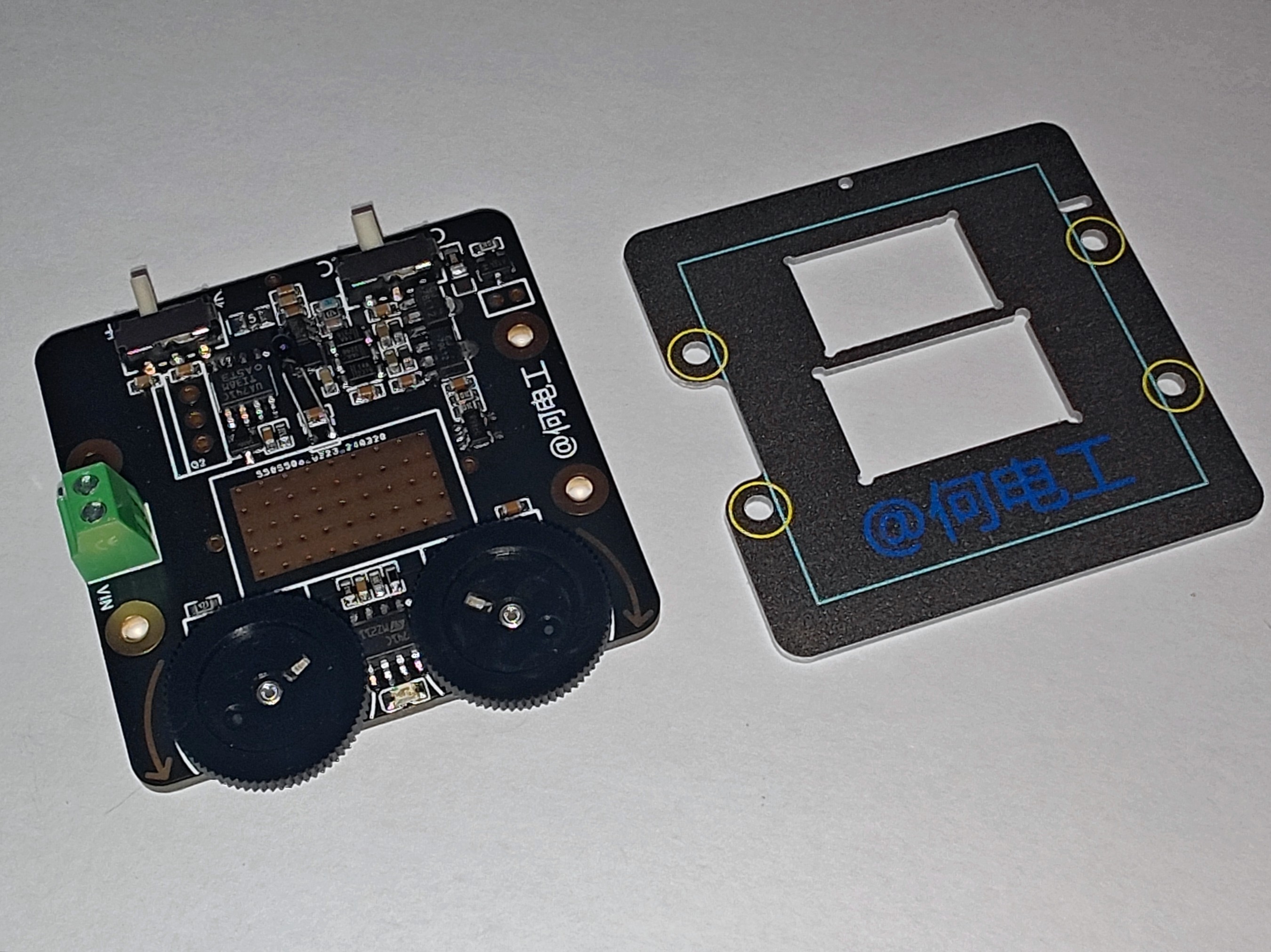
The circuit of this project is relatively simple, mainly divided into two parts: the power supply circuit and the load control circuit. The core of controlling the load is the negative feedback of the operational amplifier.
1. Current Direction:

Connect the battery to the terminal block, input the current to the meter via copper post + banana plug, and then flow out of the meter and into the load. The discharge curve is recorded via the IOTpowerCC meter.
The switch simultaneously controls both the meter power supply and the battery input load.
2. System Power Supply:

The system power comes from the 5V of the IOTpowerCC meter (an external power supply is required to power the meter when using this load, and the toggle switch on the meter must be switched).
The fan bracket board not only serves as a fan bracket but also has solder pads for spring pins (see the "Other" section for the purchase link) for drawing power and sending it to the control board.
The power supply section uses MT3608 as the main controller, utilizing the SW switch node to achieve reverse... The output voltage is ±15V, and then an LDO is used to obtain a more stable ±12V power
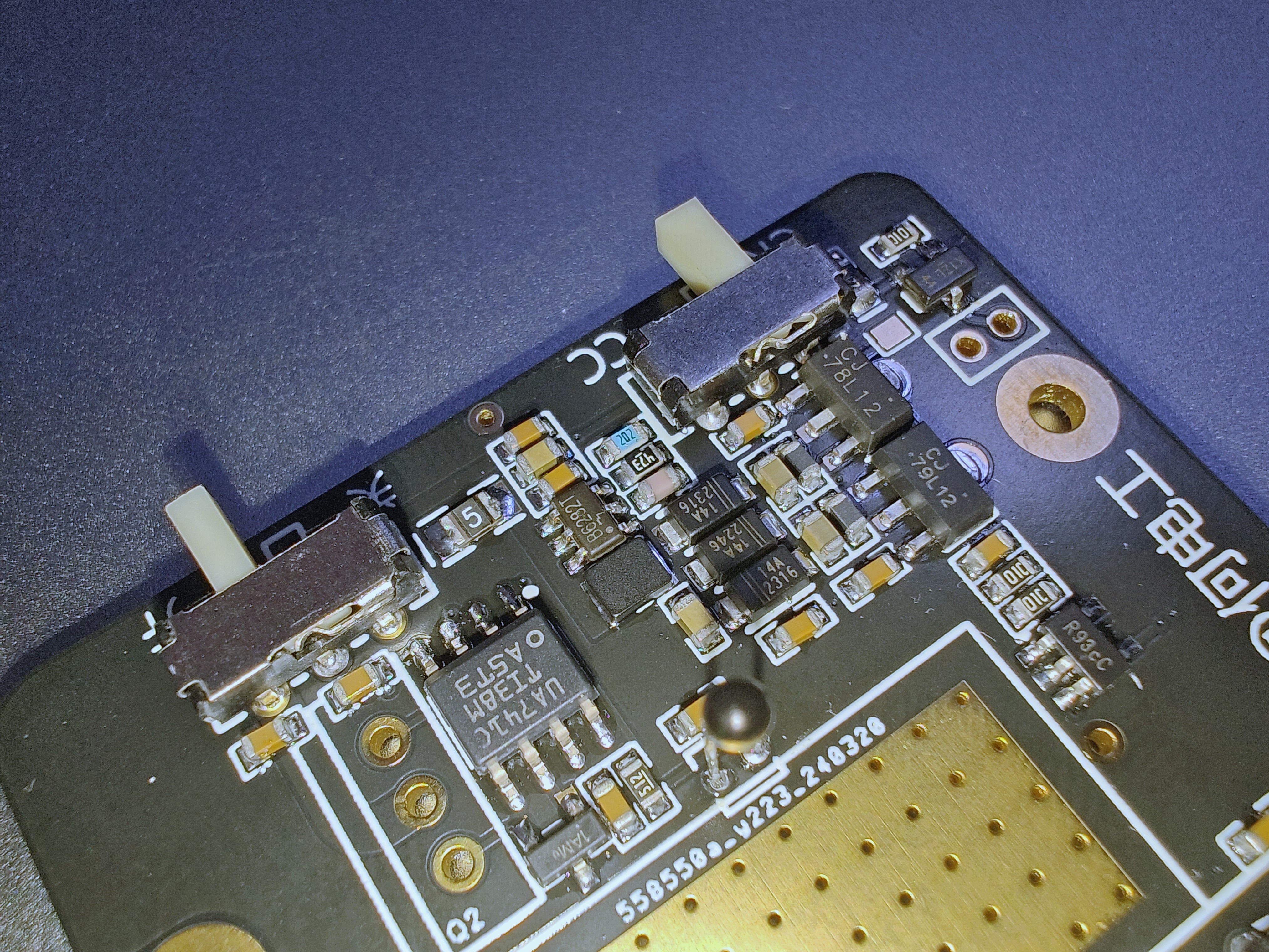
supply. The power supply section is shown in the figure above.
3. Parameter setting circuit:

This module has constant current/constant resistance load modes, which can be switched by a toggle switch, as shown in the figure above. CC and CR are marked on the PCB for easy identification.
In constant resistance mode, RP1 is used for voltage divider output reference value, and R17 above is used to limit the upper limit of the reference voltage. The minimum equivalent resistance of the load corresponding to different resistors is marked in the figure, which is convenient for users to switch according to actual needs. The default is to use an 82k resistor. It is not recommended to use the load with high current for a long time to avoid overheating.
The principle of constant current mode is similar, where R19 is used to limit the minimum current. The main difference between constant
current and constant power modes lies in the feedback source. Since the load itself provides current feedback, a fixed reference voltage is used in constant current mode, while a constant resistance mode is one where the reference voltage changes linearly with the input voltage.
Similarly, a constant power mode can be designed.
4. Load Circuit:

The load section uses a 741 op-amp to construct negative feedback. Resistor R0 not only serves as the load but also acts as a current sampling resistor for feedback; therefore, a high-power RX24-5W package resistor is used.
TIP41C is a high-power transistor, which is inconvenient to control directly with an op-amp; therefore, a 3904 is used.
During operation of the Darlington circuit under load, both the power resistor and the TIP41C will generate significant heat. Therefore, an active cooling system is required to prevent overheating.
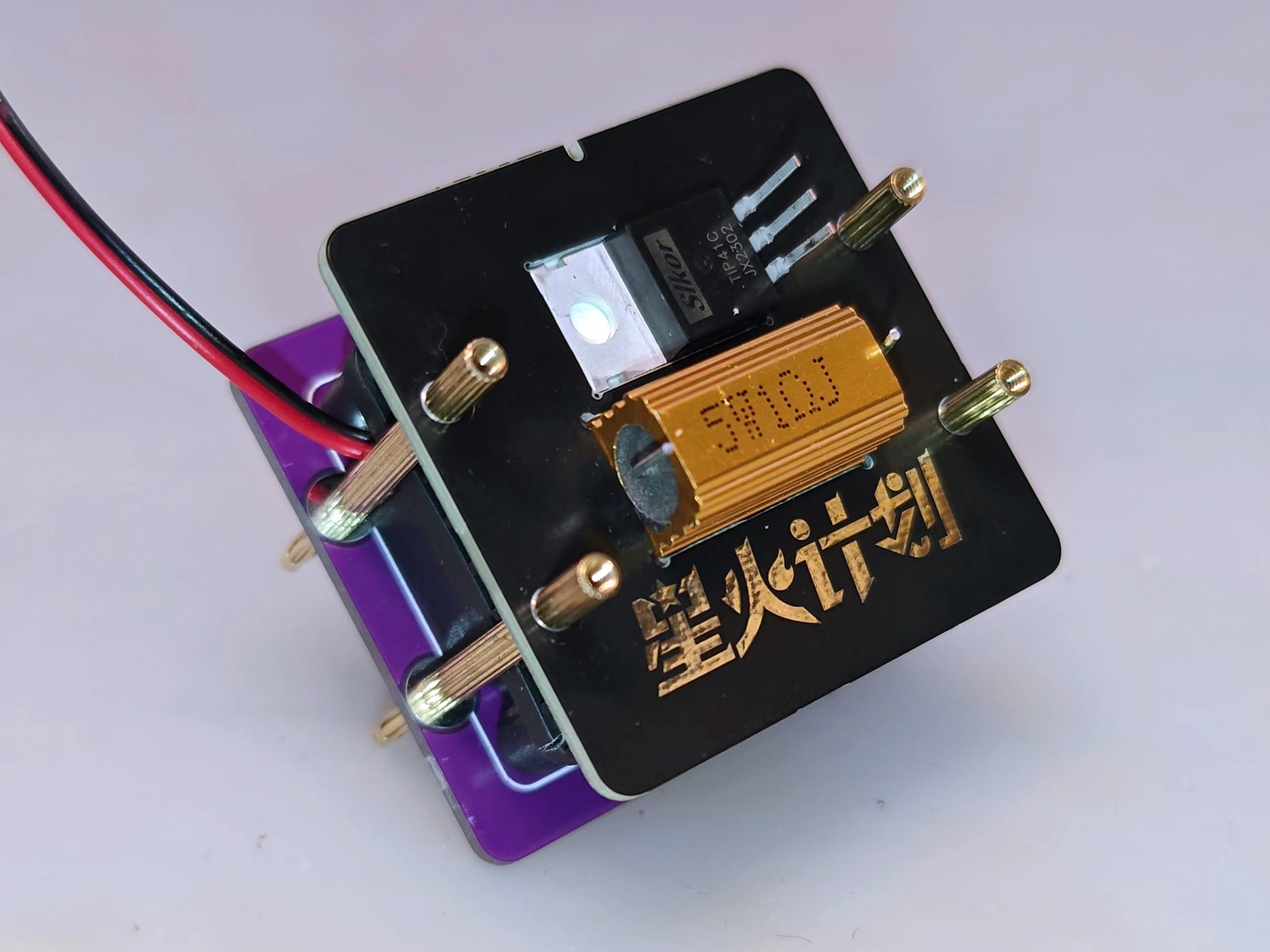
The assembled power and heatsink components are as follows: (The purple component at the top is the fan bracket).

The power resistor and power transistor are mounted in reverse on the back of the heatsink, as shown in the diagram below.
During installation, first attach the heatsink to the heatsink bracket (PCB or acrylic), bend the component leads as shown in the diagram, and then attach the components to the corresponding openings in the heatsink bracket.
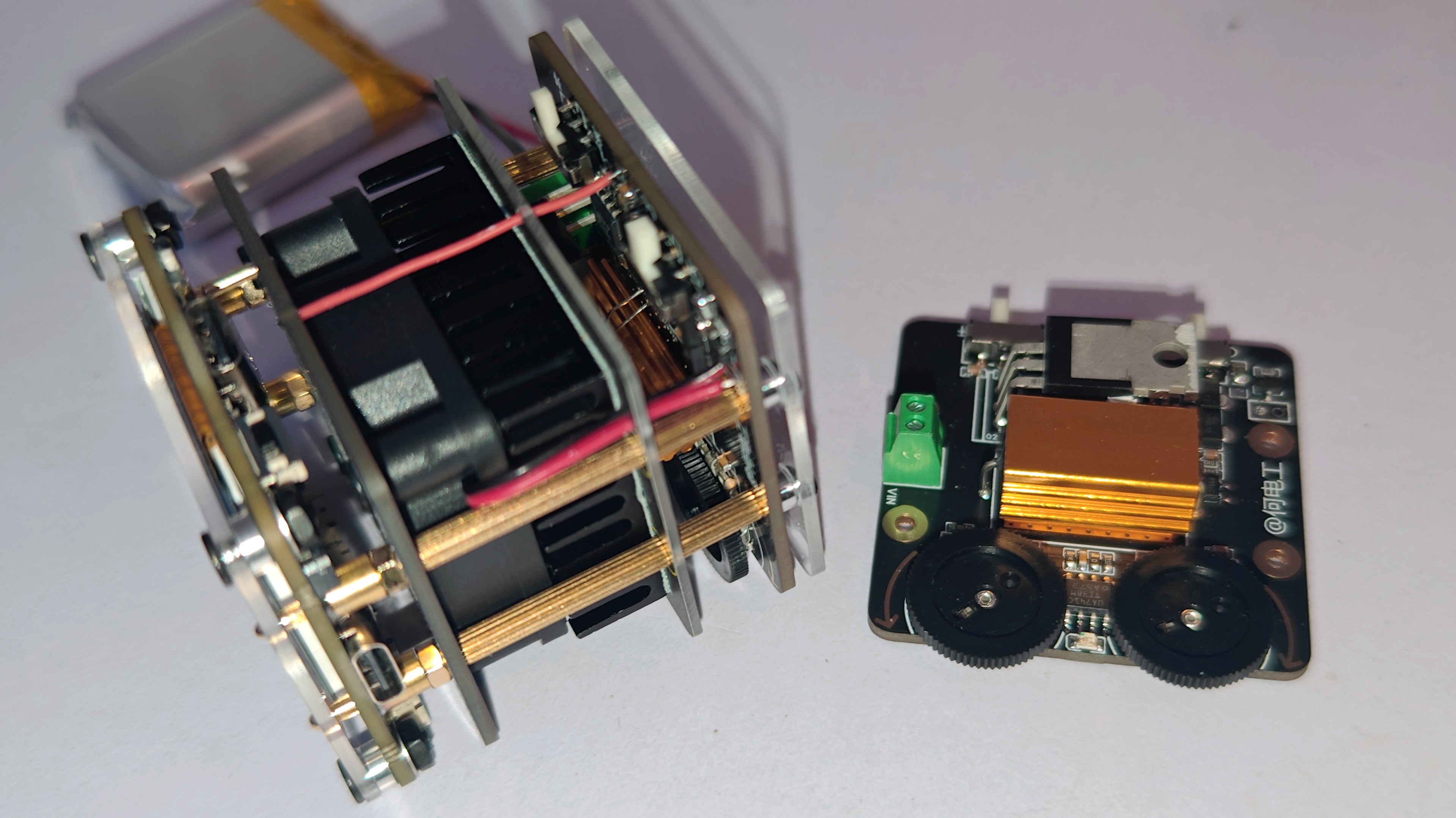
After completing the above assembly, soldering, and testing of the control board, the power and heatsink components can be inserted into the control board (note that soldering should not be done at this stage).
The stack-up of this project is relatively complex. The stack-up structure during assembly is as follows:
1. Top panel;
2. 2mm thick gasket (M2.5)
; 3. IOTpowerCC meter head
; 3.1. Copper post for meter head connection; 4.
Gasket, nut; 5. Banana plug (M2 thread) ; 6.1. M2 screw; 6. Fan bracket plate; 6.2. M2*7 stud; 6.3. 3510 fan.
6.4. M2 countersunk screws,
above 6.1-6.4, are fixed to the fan bracket plate.
7. M2*2 1+3 studs.
8. Heatsink bracket.
9. M2*9 double through studs
. 10. Load control board. 11.
2mm thick washers (M2)
. 12. Acrylic base plate
. 13. M2*8 screws.
For detailed assembly instructions, please refer to the article: Low-Cost Mini Discharge Load Assembly Instructions - JLCPCB EDA Open Source Hardware Platform (oshwhub.com).
5. Fan Temperature Control Circuit:
To prevent overheating, the module is equipped with a temperature-controlled fan start/stop circuit.
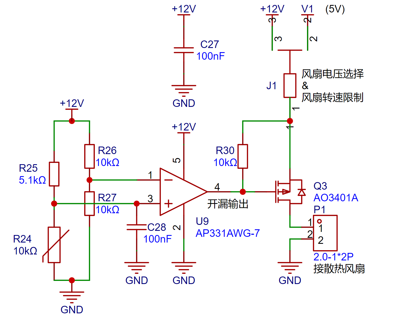
Utilizing the open-drain output characteristics of the AP331 comparator, it can easily control the AO3401. The use of MOSFETs reduces the need for external circuitry.
To ensure compatibility with 5V or 12V cooling fans, the voltage can be selected via the J1 jumper pad (a 0Ω resistor in a 0805 package is recommended for the jumper). If the fan noise is excessive, a resistor with a resistance value can be used as a jumper to limit the fan speed (generally, it is not recommended to exceed 5Ω; please test after setting the resistor to avoid the fan failing to start).
P1 does not require soldering pin headers. The purpose of P1 is to provide two pads for soldering the fan's power cable. Please refer to the assembly instructions for specific installation methods.
Circuit Function Test:
The following are actual test photos. To facilitate testing under different voltage conditions, a digitally controlled power supply is used instead of a battery input load.
1. Constant resistance mode:
Change the input voltage, keeping the load resistance constant.
2. Constant current mode:

Change the input voltage, keeping the load current constant
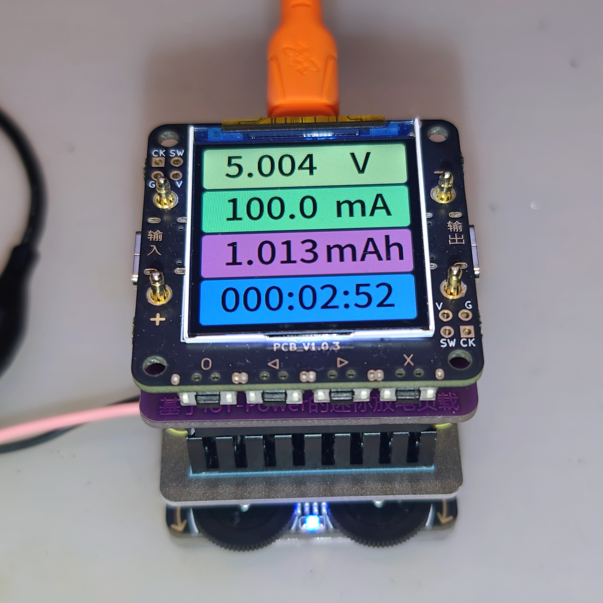
. 3. Battery discharge curve test:
Use an IOTpowerCC meter in conjunction with a host computer to record the battery discharge curve. This is the main function of this module, achieving precise low-current discharge to obtain the accurate discharge curve of a small soft-pack lithium battery. This allows for more accurate deduction of the battery
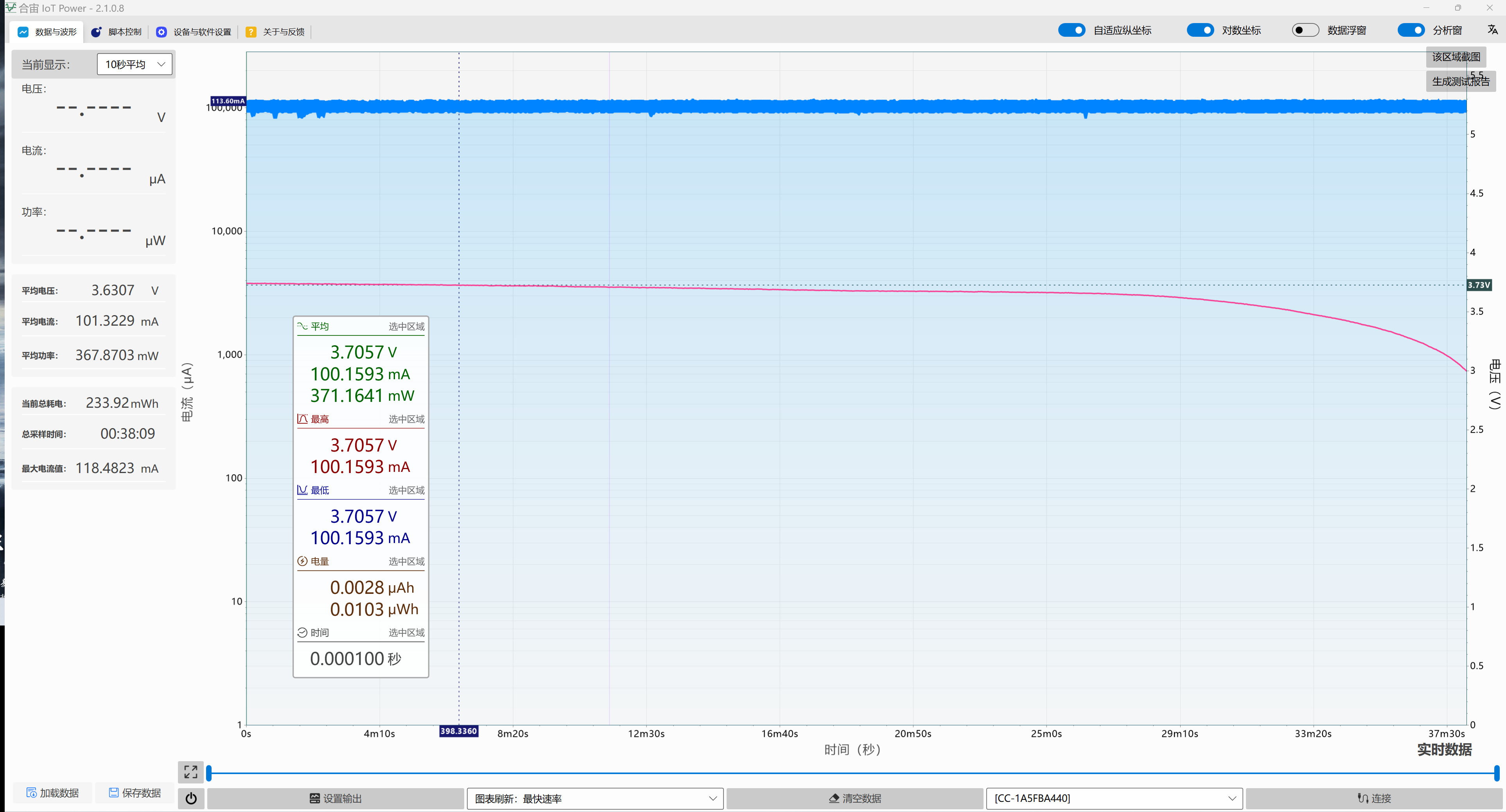
capacity from the voltage during product manufacturing. The sample battery discharge curve is shown in the figure (discharge current set to 100mA).
Precautions:
This project is only for low-power scenarios. Do not use high-power for extended periods.
The input voltage should not exceed 10V; otherwise, the control system may malfunction.
After using the load, it is a good habit to reset the load power to zero (rotate all potentiometers counterclockwise to the end) to prevent powering on under load the next time!
When securing or disconnecting the battery leads to the connector, avoid touching the Type-C port housing with the screwdriver, as this will short-circuit the battery, which is extremely dangerous!
To prevent this, it is recommended to insert a dust plug or cover the Type-C port with tape before using the load.
Do not use this load unattended, especially during battery discharge. Monitor the device and battery status continuously to prevent accidents!
Note: Some batteries lack a protection board; prolonged discharge may lead to over-discharge, causing irreversible damage, including but not limited to swelling, fire, and explosion!
Use this open-source project at your own risk. The open-source author and platform are not responsible for any losses, including but not limited to personal injury and property damage, resulting from the use of this project. Please test and ensure the load is functioning correctly before use, ensuring legal and compliant use. You are solely responsible for any consequences.
Other:
Some component purchase links on Taobao: (Other components can be purchased directly from LCSC Mall)
Not an advertisement, for reference only.
10K potentiometer: Dial/gear potentiometer B503 single three-pin 50K diameter 16*2MM karaoke volume control switch - Taobao (taobao.com)
Cooling fan: Yingxun 3510 35X35X10MM 3.5*3.5*1CM 3.5CM/cm 5/12/24V cooling fan - Taobao (taobao.com) Heatsink
: (35*35*10) Aluminum heatsink with slotted grooves and thermal adhesive backing for Raspberry Pi CPU router motherboard electronic chip heatsink - Taobao (taobao.com)
Banana plug: 2mm banana plug/2mm pure copper gold-plated/hexagonal thread/panel-mounted banana connector banana socket - Taobao (taobao.com)
Copper pillars for meter connection: (C2*C4*5+C3*1.6 Copper sleeve ¢2¢2.5¢3¢4 raised step copper pillar SMT surface mount PCB soldering support isolation pillar through hole without teeth - Taobao.com
Spring pin: (Model H053) Pin tube diameter 1.5mm Classification spring pin connector pogo pin terminal copper pin current signal probe - Taobao.com
2mm thick gasket: (d2.1*D4*2) Aluminum sleeve aluminum alloy shaft thickened gasket screw joint tube sleeve round metal ring washer M2 M2.5 M3 M4 M5 - Taobao.com
High power resistor: (1Ω) Gold aluminum shell resistor RX24 5W/10W/50W/200W/500W automotive high power resistor component collection - Taobao.com
Illustrated assembly instructions see article: Low cost mini discharge load assembly instructions - For detailed instructions on using the open-source hardware platform OSHWHub
load, please see the video: [Bilibili] Low-Cost Mini Discharge Load.
If you have any questions or suggestions about the project, please leave a comment.
You are also welcome to join my technical exchange group: 1016193632


 京公网安备 11010802033920号

 2Z16A
2Z16A


