Video Link:
[Bilibili Video - Function Demonstration and Introduction] [SkyStar Expansion Board] https://www.bilibili.com/video/BV1GZskehEo7/?share_source=copy_web&vd_source=313763c4cf8391e7e2d0b4c06a66f331
Project Introduction
This expansion board is designed for the logistics handling track of the 2025 Industrial Training Competition. The main controller is SkyStar STM32F407VET6. This expansion board can drive stepper motors, communicate via OpenMV, use Bluetooth wireless communication, display via serial port, debug with buttons and OLED screen, and learn servo control.
Project Functions
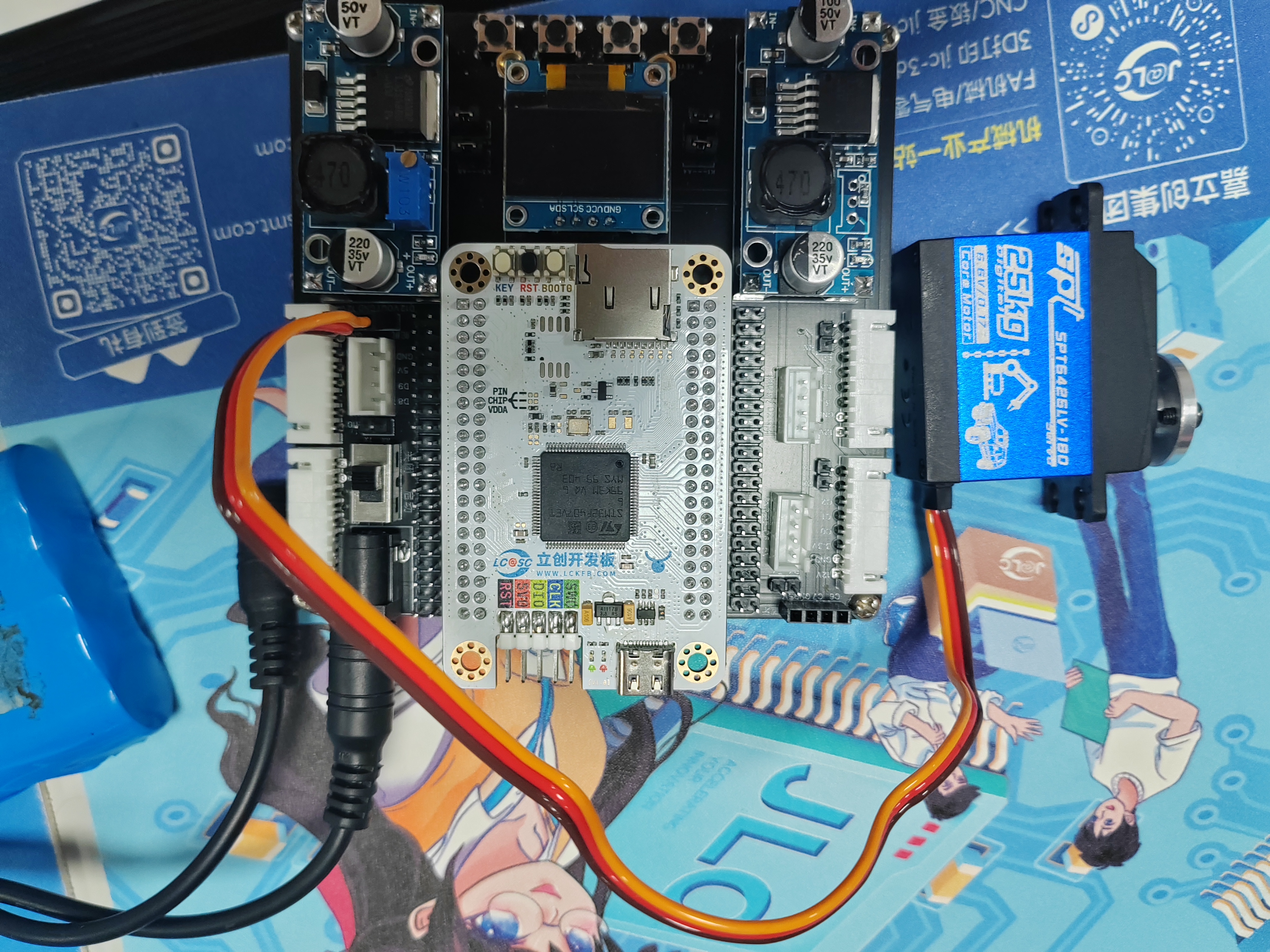
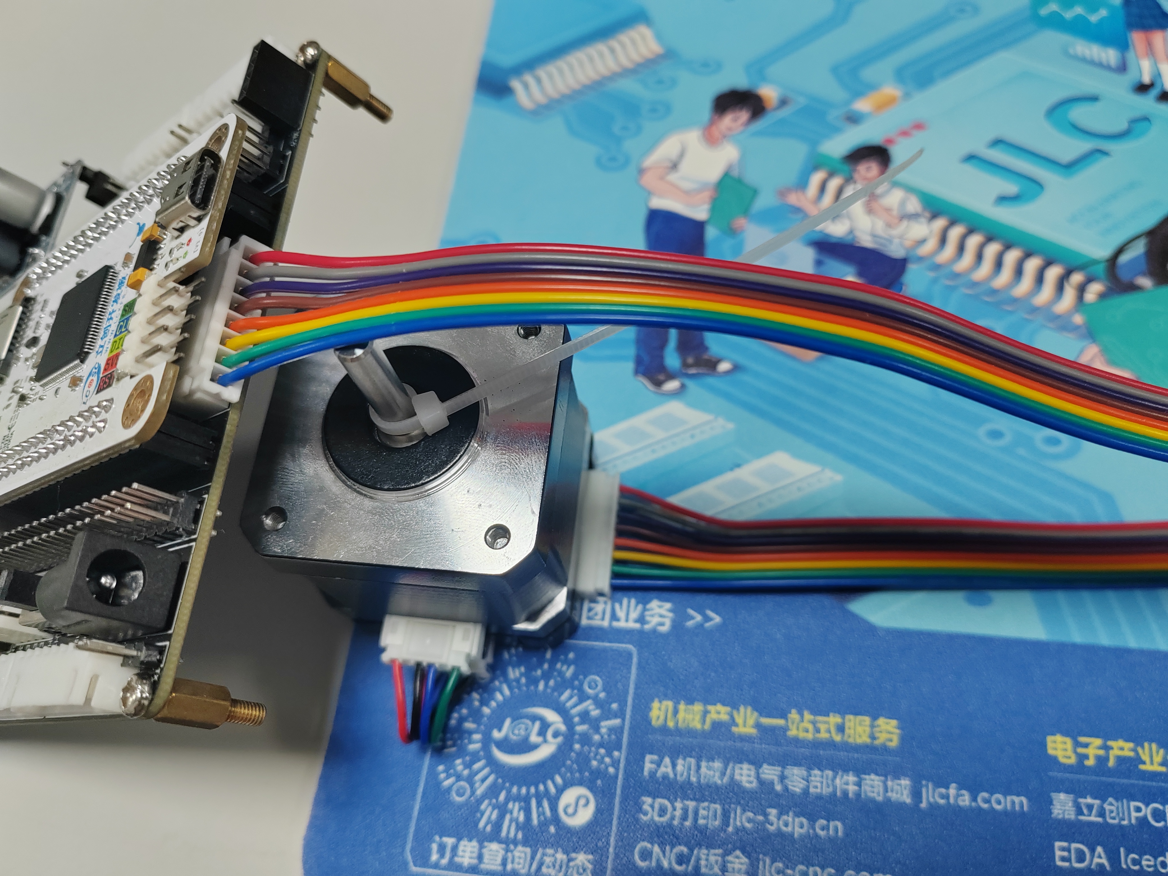
This project is an expansion learning board designed based on the SkyStar STM32F407VET6 development board of LCSC for preparing for the logistics handling track of the Industrial Training Competition. There are two 8P terminals on each side of the board that can be connected to stepper motors (Taobao Zhang Datou stepper motors) as wheel drive motors for the training vehicle. There is also a motor interface at the front that can be used to connect the sliding rail lifting motor. There is one servo interface for cargo gripping. There are two OpenMV interfaces for serial communication with cameras; one camera identifies and locates the cargo, and the other is used to recognize QR codes to obtain the handling sequence list. There is one serial screen interface for displaying the acquired handling information. Four buttons are used for parameter adjustment, and an OLED screen displays data interaction.
PCB Design Description:
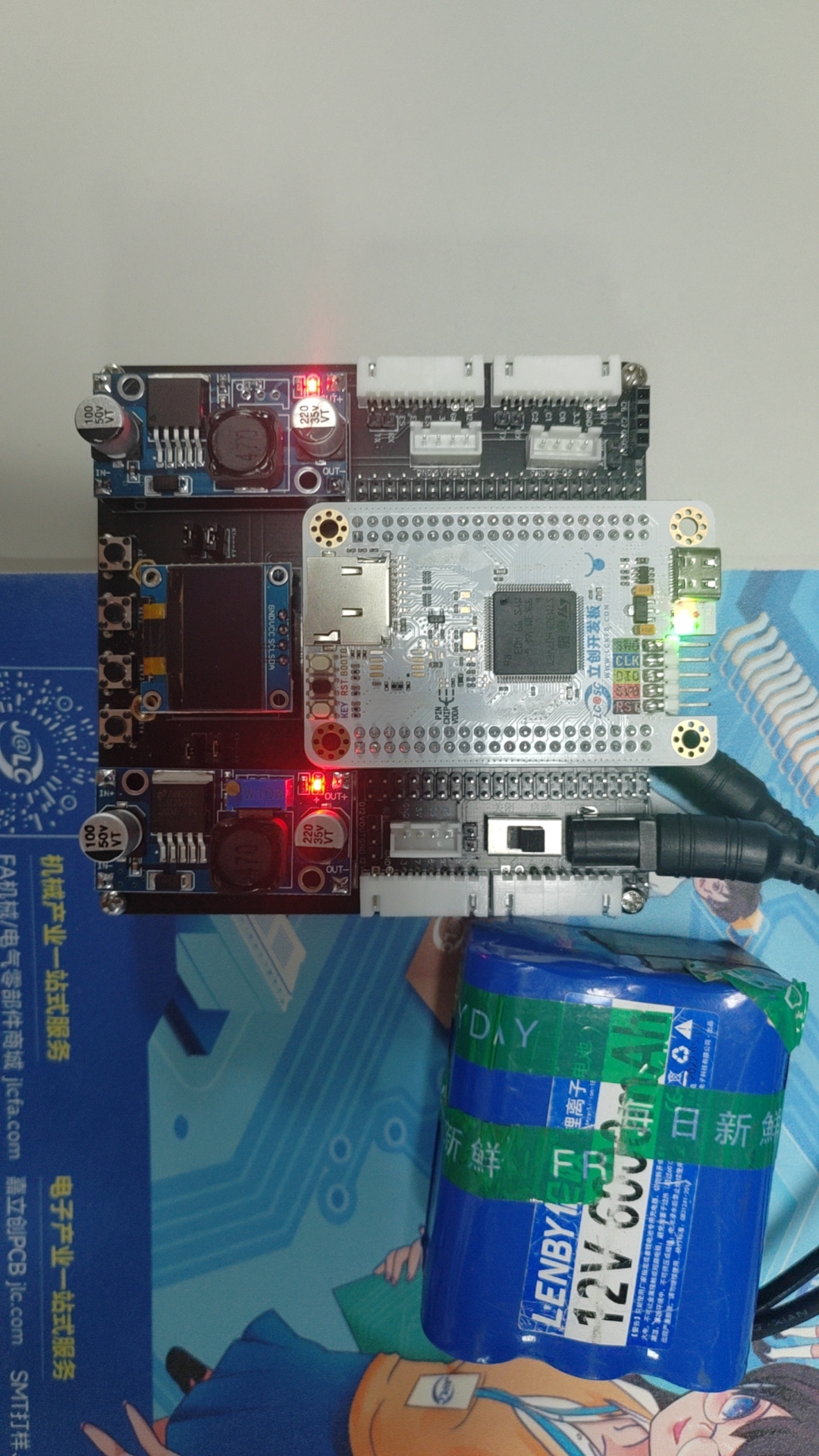
This project consists of four main parts: power supply, main control circuit, peripheral interface circuit, and debugging module.
Example Figure 1 – Main Control Circuit:

All I/O pins are additionally brought out for easy subsequent development and debugging.
Example Figure 2 – Peripheral Interface Circuit:

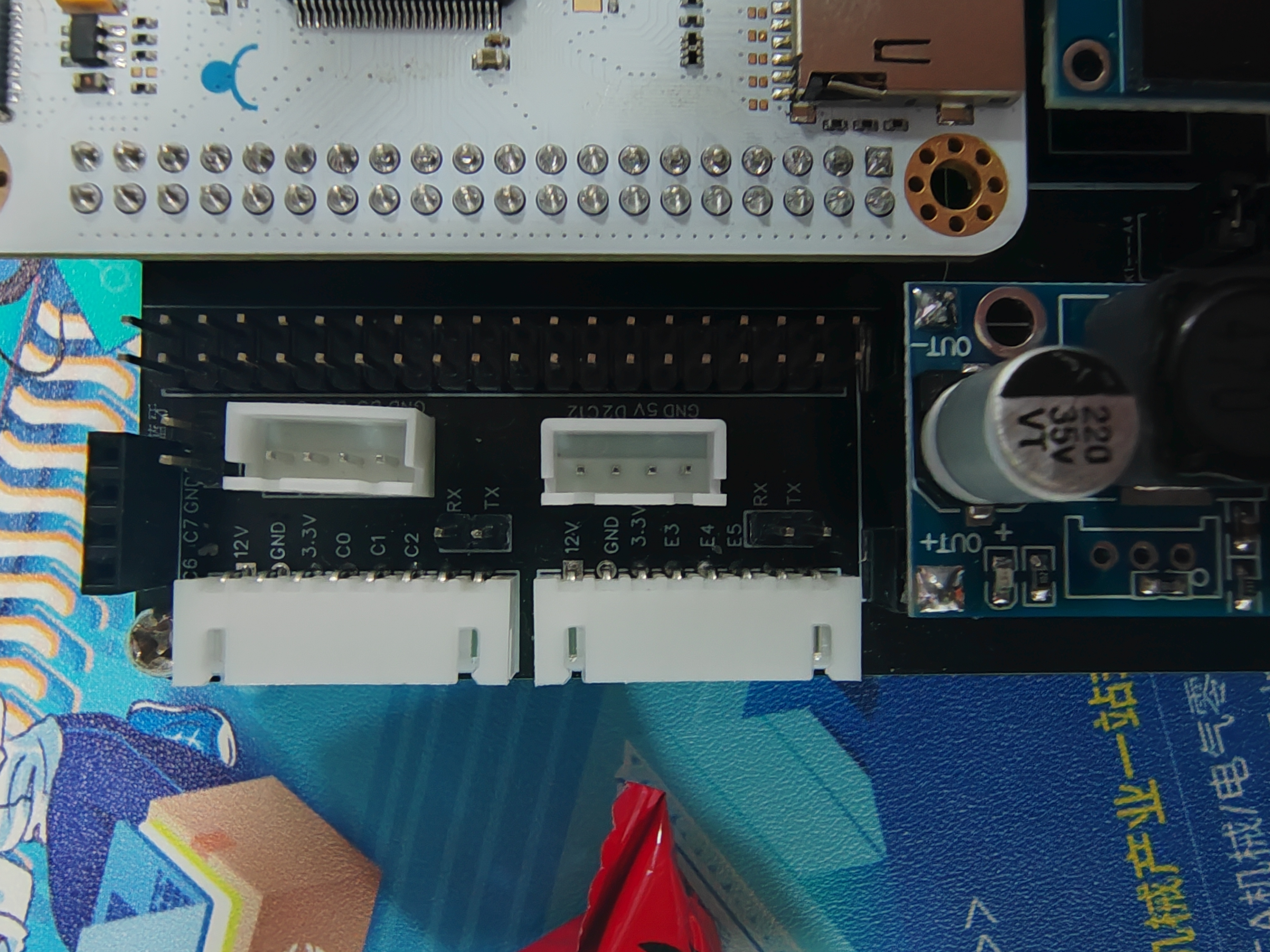
Each stepper motor can communicate with the main control via serial communication. Here, I have brought out the stepper motor communication interface and one serial port of the microcontroller. If serial communication is needed to control the motor, jumper caps can be used for connection. If serial communication is not needed, the pins can be used for other purposes.
Example Figure 3 – Debugging Module Circuit:
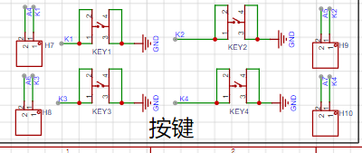
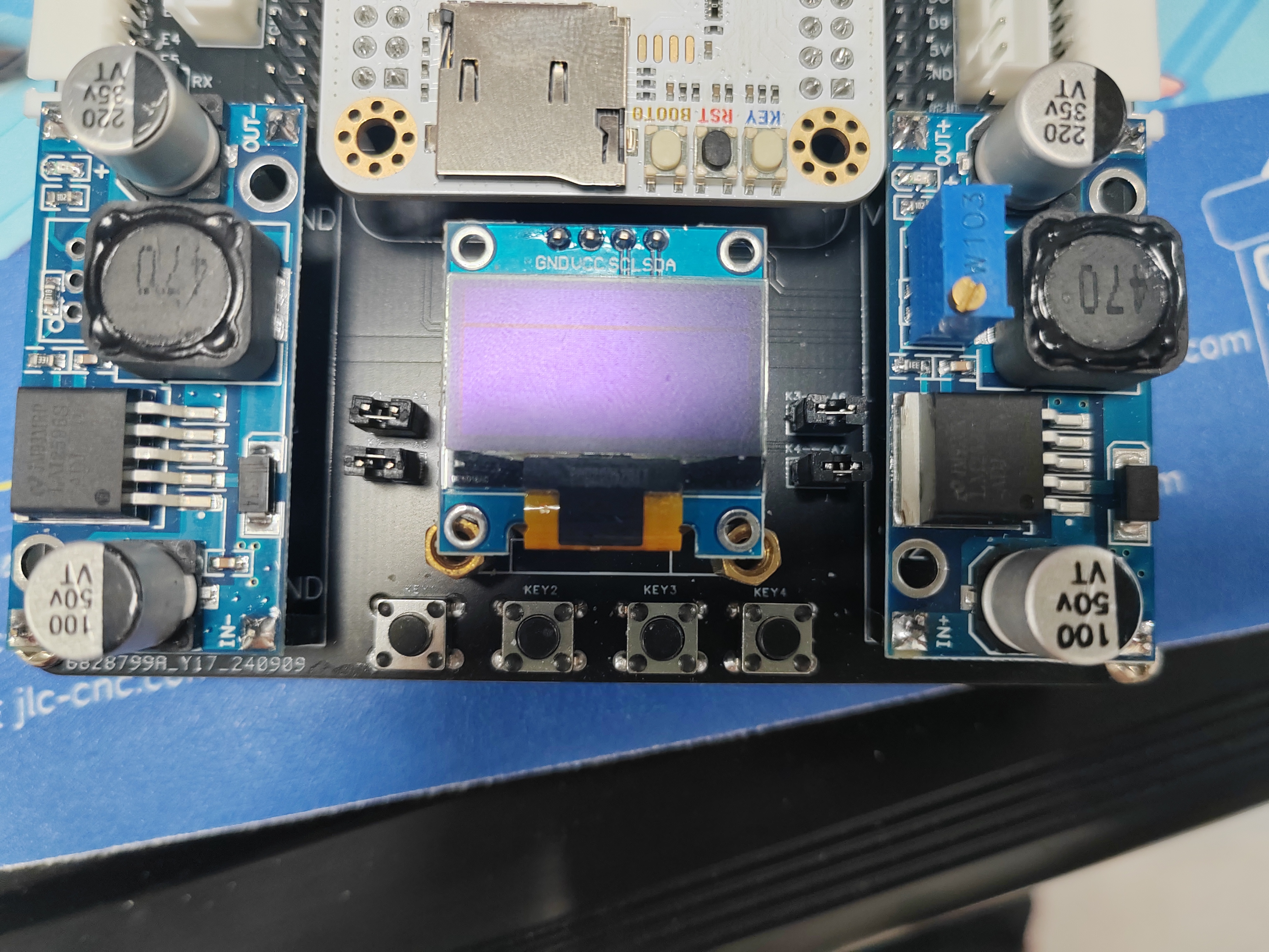
The button interface and the corresponding microcontroller I/O port are brought out separately. If button debugging is needed, jumper caps can be used for connection, or other purposes can be used.
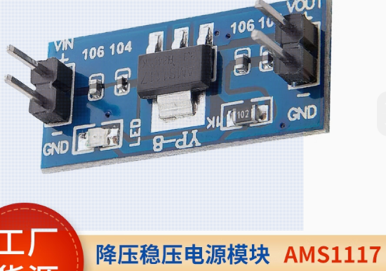
Example Figure 4 -- Power Module Circuit:
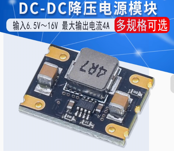
Uses an LM2596 voltage regulator module. One fixed 5V output powers the microcontroller, camera, serial port screen, and Bluetooth; one adjustable output powers the servo motor. Two voltage regulator modules are used to prevent the servo motor power supply circuit from affecting the power supply to the microcontroller and other modules.

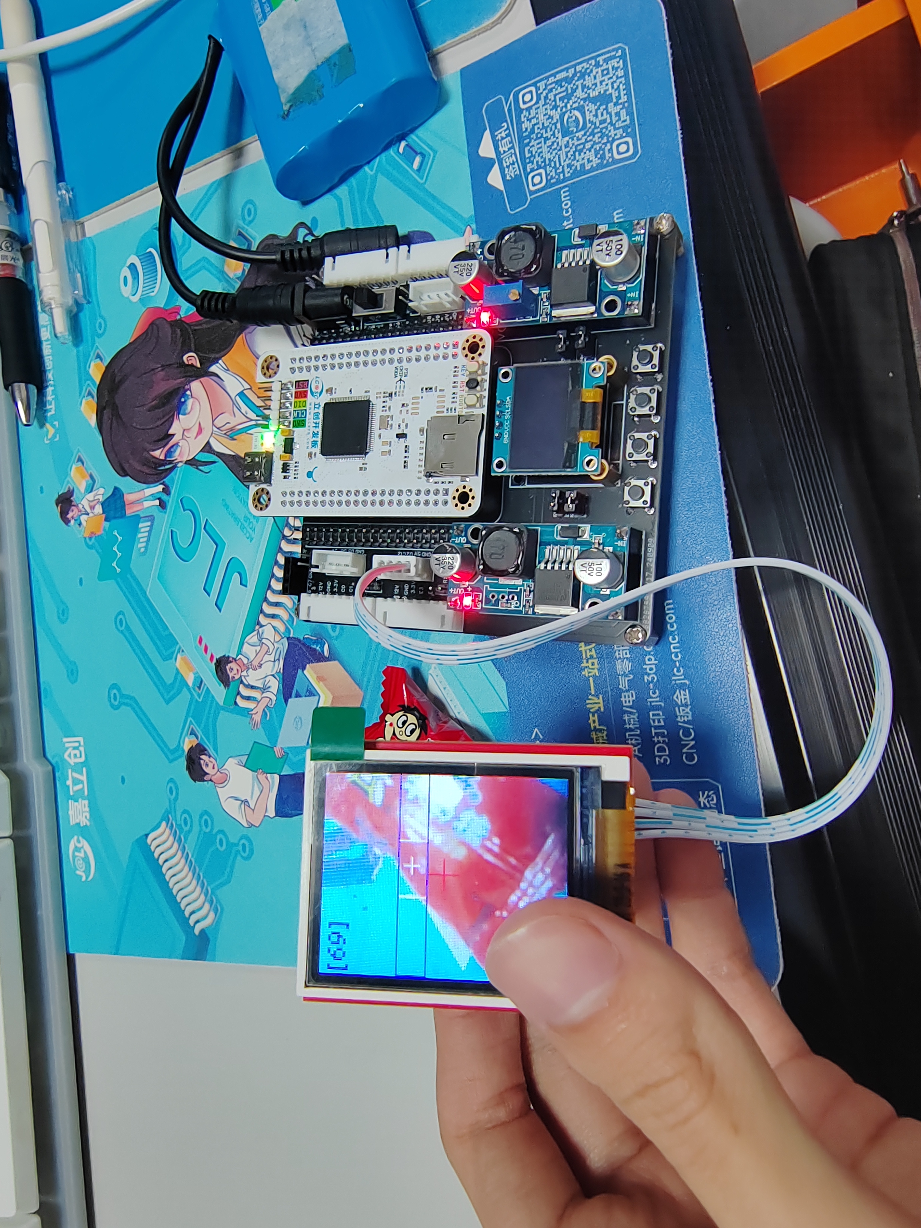
Software code includes:
one code for communication with OpenMV, enabling camera line tracking; the camera returns the midpoint coordinates of the line.
One stepper motor drive test code.

Important material:
The motor was purchased from Taobao (Zhang Datou stepper motor).
Assembly instructions:
Bluetooth module assembly,

servo motor module assembly,
stepper motor assembly,
power supply battery (12V lithium battery pack).

[Image of the actual product]
STM32F407_Project----Stepper.zip
STM32F407_Project----openmv.zip
034815ce578b2e80498387381a3e97c7.mp4
PDF_Smart Car--Based on SkyStar STM32.zip
Altium Smart Car - Based on SkyStar STM32.zip
PADS Smart Car - Based on Skystar STM32.zip
BOM_Smart Car--Based on Skystar STM32.xlsx
91613
Intelligent access control system
A smart access control system based on the STM32F103C8T6 microcontroller supports RFID card, fingerprint, and password unlocking (reading and writing to internal flash memory is retained even after power loss). The ASRPRO Tianwen development board is responsible for broadcasting and voice recognition.
Components:
STM32F103C8T6 minimum system board
, 12V to 5V step-down module,
5V to 3.3V module
, OLED 0.96-inch four-pin
RC552 module,
AS608 fingerprint module,
16x6*5*5 tactile switch matrix keyboard
, buzzer module,
130 DC motor ,
ASRPRO development board with microphone (not the core board),
DC005 female connector (for lithium battery),
SS-12D10L5 toggle switch,
one 1k through-hole and surface mount resistor, and LEDs (0805 surface mount package, used for lighting simulation and power indicator).
Functions:
Access control:
fingerprint, RFID card support login, registration, and deletion modes.
Passwords only support registration and login.
Matrix keyboard: * key for login, # key for registration password, = key for confirmation password, other keys can be freely entered. Passwords support a maximum of 6 digits.
Display and feedback:
The OLED displays the current mode and on/off status in real time, and indicates success or failure.
A buzzer will sound a long response after the access control unlocks; a buzzer will sound a rapid error if various errors occur (login failure, registration while not logged in, deletion).
ASRPRO:
Customize voice recognition prompts using the Tianwen Block graphical programming software. These prompts control the switching of ID card, fingerprint, and password lock modes. After opening the door, lights and motors can be turned on or off via voice. After voice recognition, corresponding commands are sent to the STM32 via serial port. The serial port callback function switches modes and statuses according to the commands. (

Tianwen Block settings ↑)
Door.rar
PDF_Smart Access Control System.zip
Altium Smart Access Control System.zip
PADS Smart Access Control System.zip
91614
Multi-protocol desktop charging station 2.2
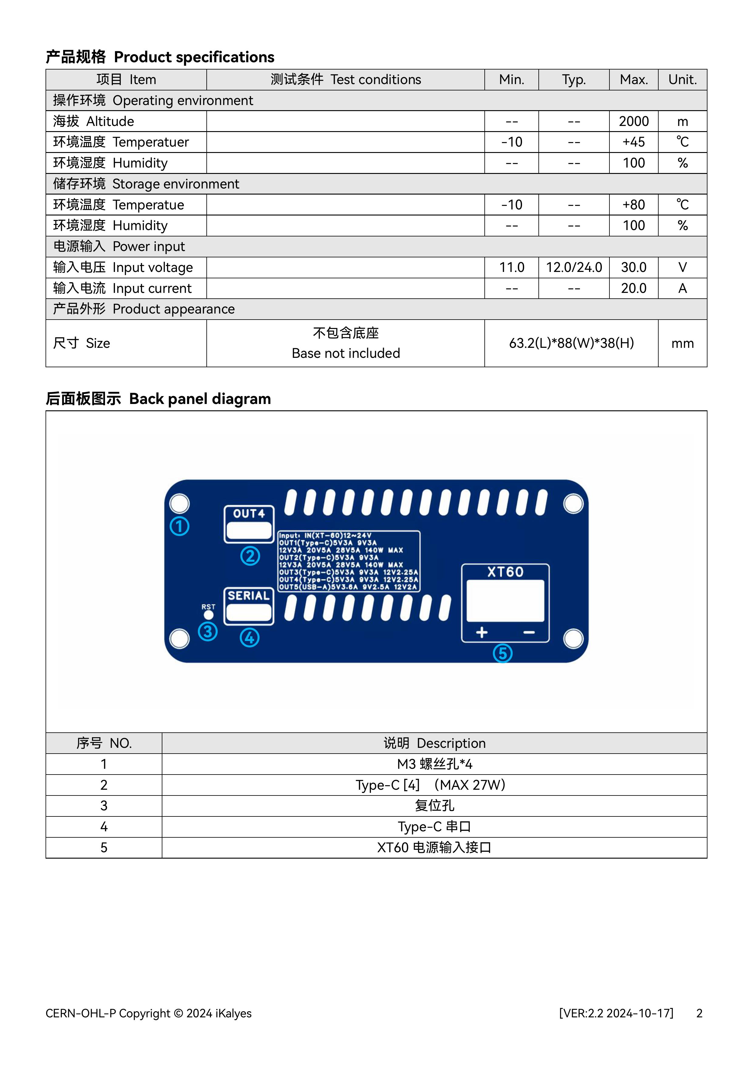
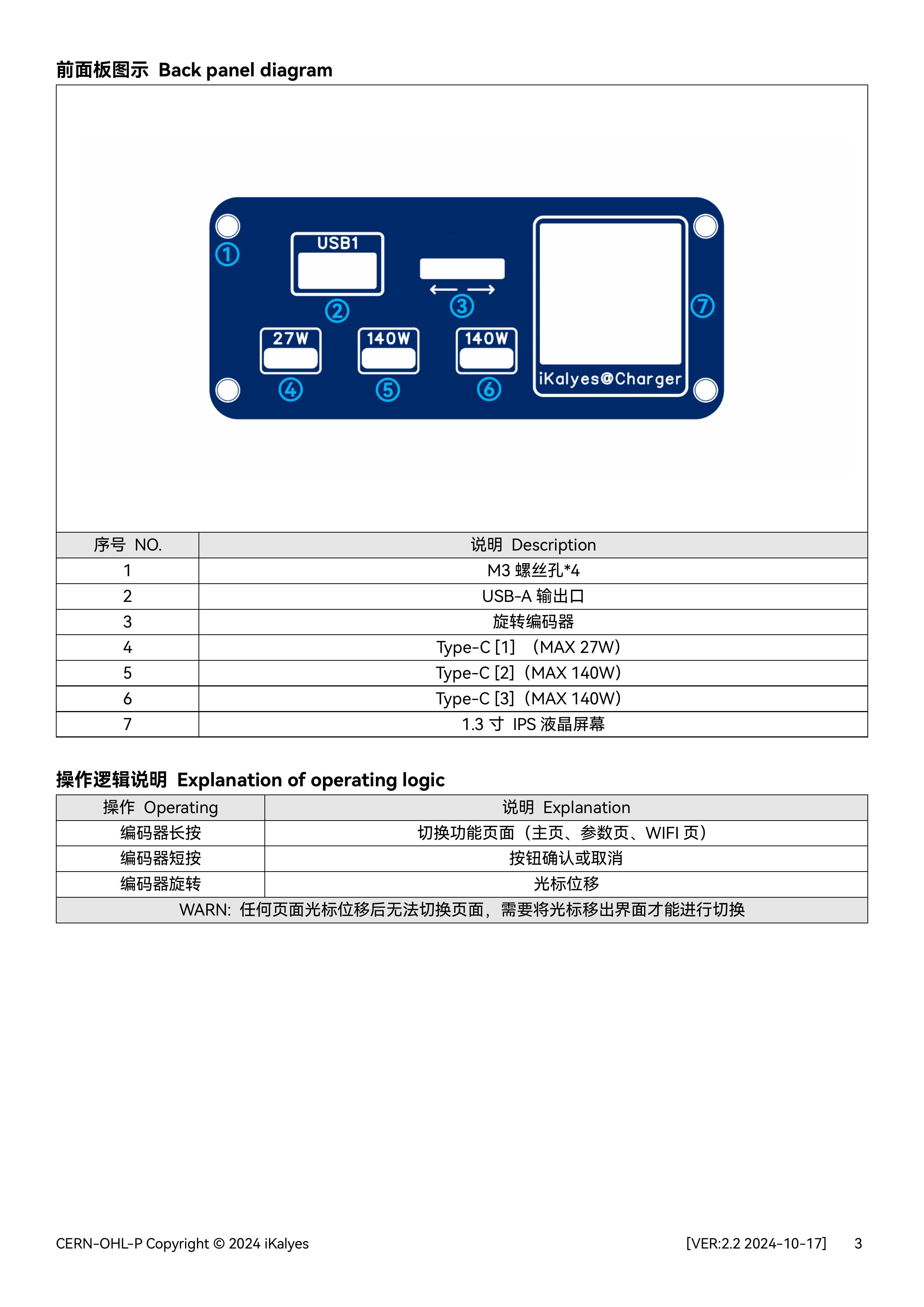
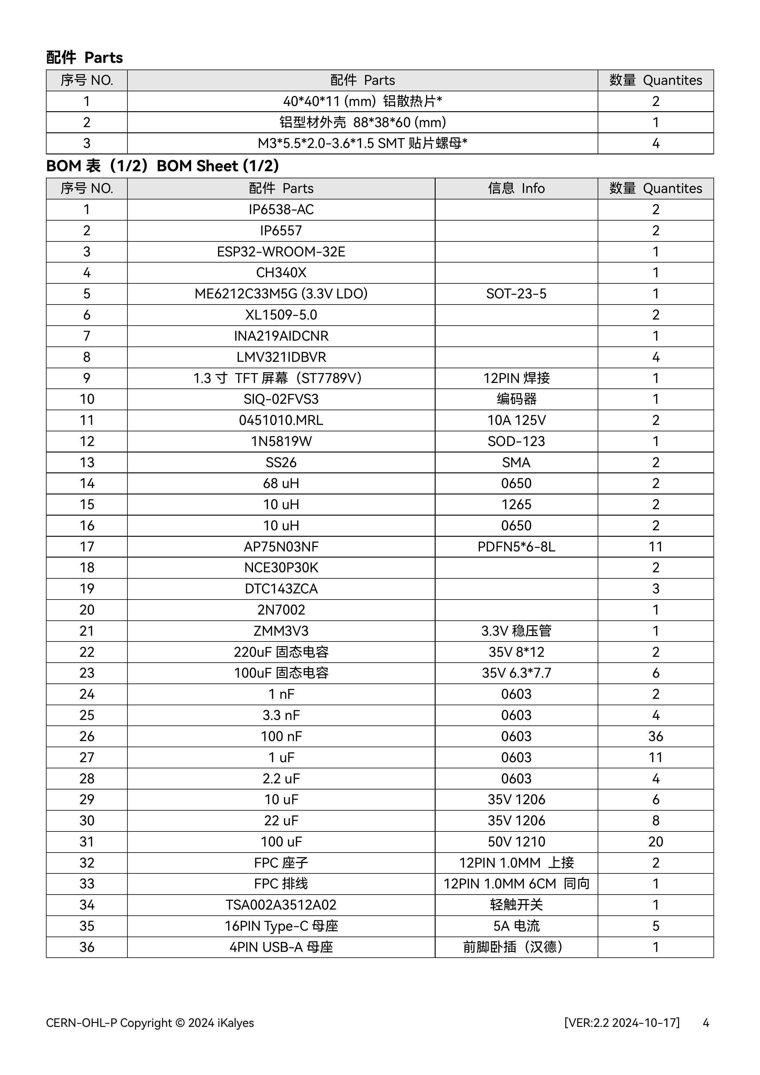
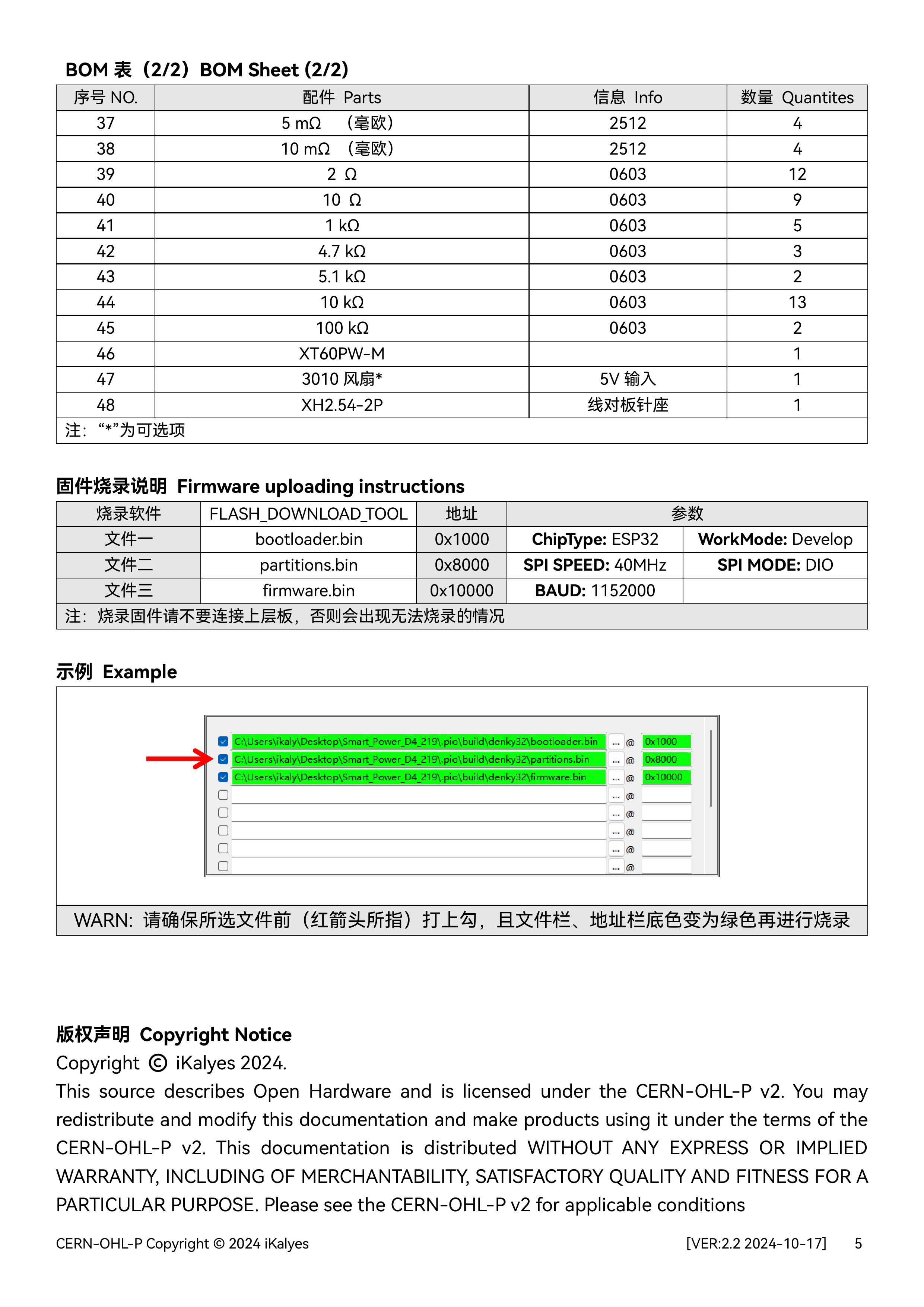
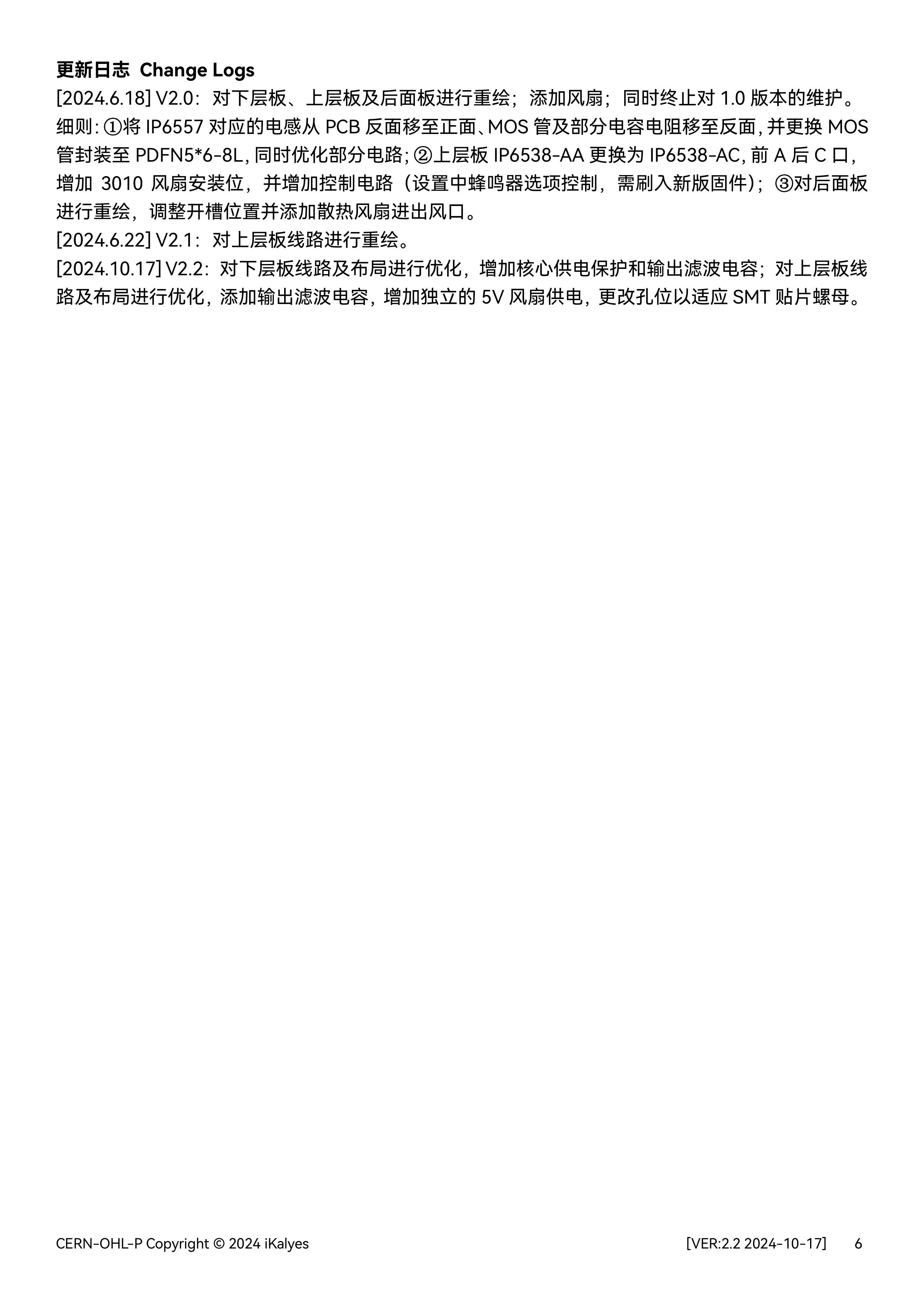
This is a desktop charging station (version 2.2) with four USB-C ports and one USB-A port, featuring voltage, current, and power monitoring, and is based on the Oringin open-source IoT multi-protocol power supply.
Firmware2.0.zip
Desktop Charging Station Source2.0 Code.zip
Multi-protocol desktop charging station 2.0 model.step
Multi-protocol Desktop Charging Station 2.2 (User Manual).pdf
PDF_Multi-protocol Desktop Charging Station.zip
Altium Multiprotocol Desktop Charging Station.zip
PADS Multi-Protocol Desktop Charging Station.zip
BOM_Multi-protocol Desktop Charging Station.xlsx
91615
APM/PX4 CAN Expansion Module
APM, CAN module
Project Introduction:
This module is an expansion module for the CAN bus interface of the APM flight controller.
Project Functionality:
When the flight controller's interfaces are insufficient, the CAN interface of this module can be connected to the flight controller's CAN interface. The wiring of this module is the same as the wiring on the flight controller. Functionality can be enabled on the flight controller.
Project Parameters:
It can connect to a buzzer, 4 PWM outputs, an LED strip, three serial ports, two I2C ports, one SPI port, C_R connects to analog current, C_T connects to analog voltage, C-R2 is the current of the second battery if there are two batteries, BAT2 is the voltage of the second battery
...
Rendering Images,
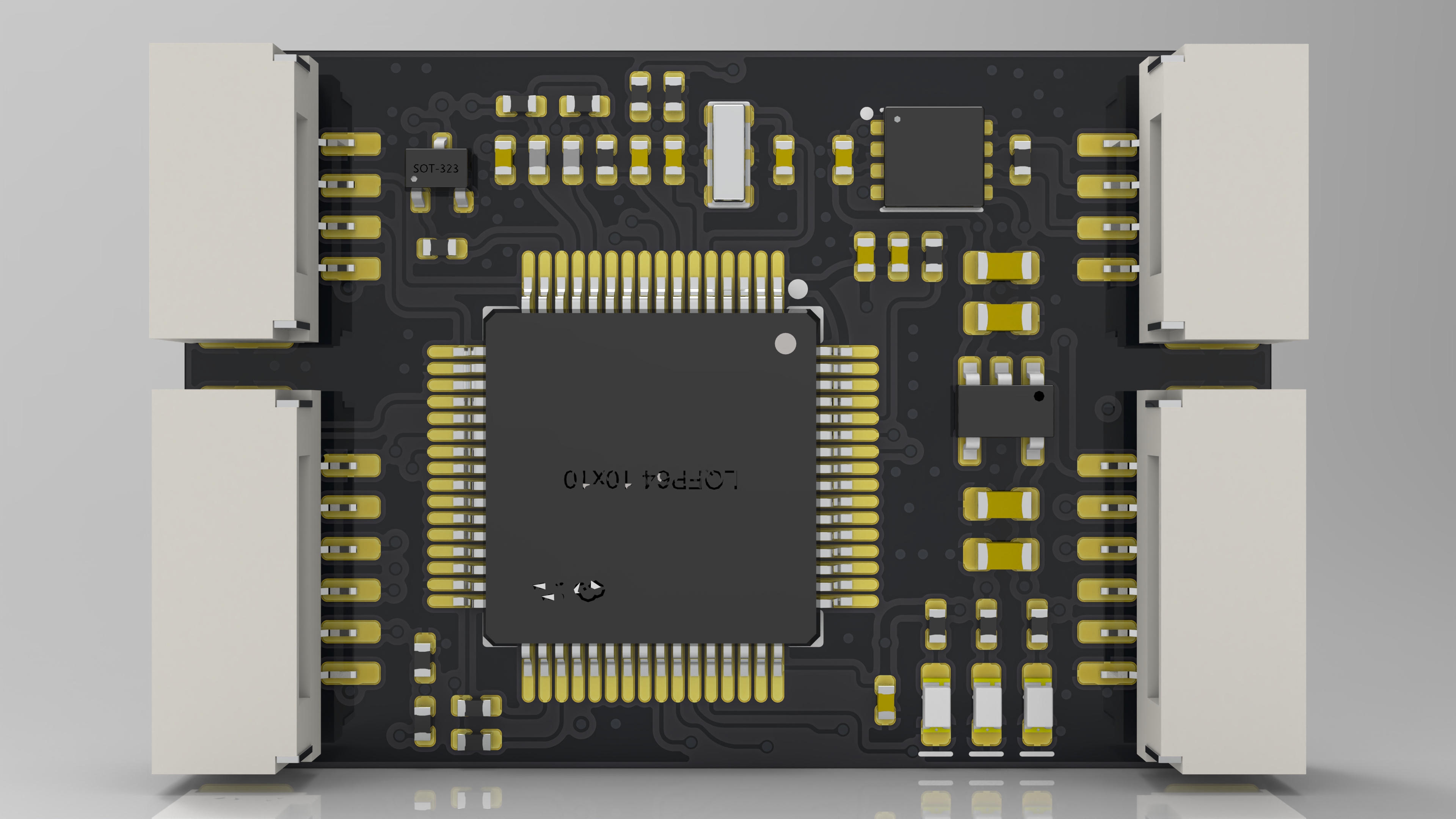

Physical Images,
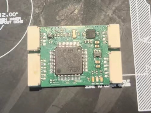
Wiring Diagram

AP_Periph_with_bl.hex
PDF_APM-PX4 CAN Extension Module.zip
Altium_APM_PX4 CAN Extension Module.zip
PADS_APM_PX4 CAN Extension Module.zip
BOM_APM_PX4 CAN Extension Module.xlsx
91616
electronic

 If you have any questions, please join our discussion groups: 754881030 (original author's group) 790715767 (my group)


 京公网安备 11010802033920号

 MI-P24-MXZ


