Project Description:
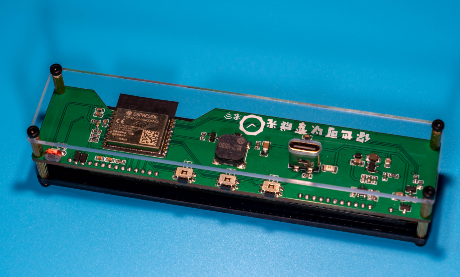
You've probably seen the appealing display of the VFD screen before. This project is based on my learning experience with ESP32. It's a retro desktop clock made using a FUTABA VFD screen (13-ST-GINK) and an ESP32-C3 as the main controller. It connects to the internet via 2.4G Wi-Fi to get the time and displays the local temperature and humidity (using an independent wireless temperature and humidity sensor; if the sensor isn't used, it can be set to display the date).
Clock dimensions: 117*27.2*26.7mm.
The clock uses 5V power supply. At maximum brightness, the average operating current is approximately 280mA, and the instantaneous current when the buzzer sounds is 700mA. It is recommended to use a 5V 1A adapter or one with a higher output current.
The average current in standby mode with the display off at night is approximately 84mA.
(Bilibili video
open source license
: Creative Commons Attribution-NonCommercial-Use)
Project-related functions
: Function 1: WIFI network connection, HTTP to obtain and display internet time.
Function 2: Wireless temperature and humidity sensor to obtain temperature and humidity; can be placed anywhere indoors without metal shielding (uses my open-source wireless thermometer and hygrometer).
Function 3: Automatic brightness adjustment.
Function 4: Temperature and humidity abnormality alarm.
Function 5: Night display off.
Project attributes:
This project is being publicly disclosed for the first time and is my original work. This project has not won any awards in other competitions.
Project progress
: Schematic diagram,
PCB layout
, outer shell, front panel (discarded due to not meeting prototyping requirements; draw if needed).
PCB prototyping application, panel prototyping application, component application from LCSC
, porting, programming, bug fixing, iterative
cutting of acrylic panels, purchasing copper pillars to make a sandwich structure outer shell.
Open source project completion
design principle:
Most components are matched with LCSC for easy purchase and manufacturing. VFD screen and photoresistor need to be purchased separately. A BOM for clock and thermo-hygrometer integration is provided in the attachment. CH571F thermo-hygrometer, 22uH, LED light, and CJ2302 need to be purchased separately. Please point out any omissions.
The outer shell is made of two acrylic sheets (3mm front panel, 2mm back panel, or both 3mm) with M2*9 double-through knurled copper pillars, M2*8+3 knurled copper pillars, and M2*5 screws for fixing. Acrylic sheets can be cut by Taobao (3mm gray transparent acrylic sheet or 2mm colorless transparent acrylic sheet).
The design block diagram shows
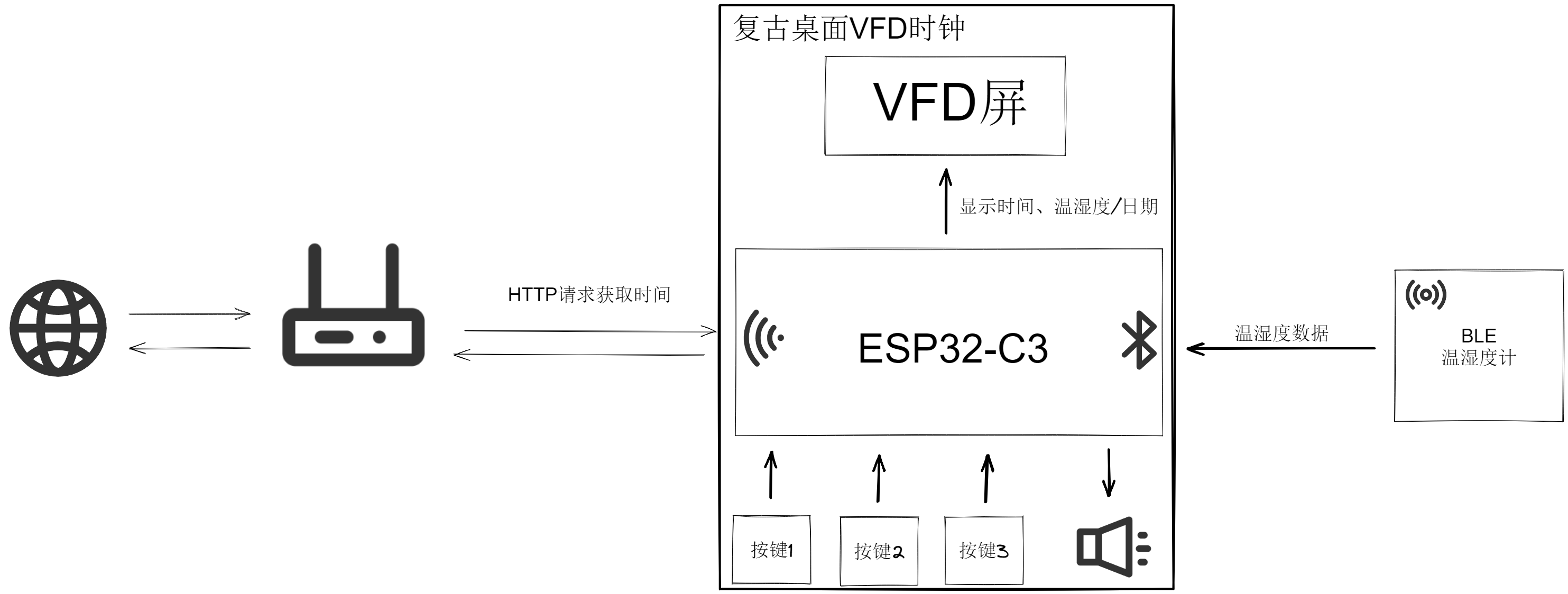
a 5V to 3.3V converter.
The ESP32-C3 only consumes more power when using Wi-Fi HTTP requests for time synchronization. Maintaining a Wi-Fi connection and performing BLE scanning draws approximately 90mA current at 3.3V. The RT9193-33GB provides sufficient power, so a DC-DC converter wasn't used for step-down.
The VFD screen driver circuit (screen purchase link)
uses a FUTABA 13-ST-84GINK screen. The datasheet recommends a 5V logic power supply, but I've verified it using 3.3V for over a month without issues. This screen has a built-in driver IC; it only needs power and communication to function properly. The screen requires approximately 32V and a 3.9V filament power supply. The 32V boost converter uses an SGM6601.
The filament power supply is taken from the 5V power supply of the USB port, and a diode is used to reduce the voltage to approximately 3.9V (do not use diodes for step-down for unstable current). This also raises the filament potential. The filament power supply uses a PMOS transistor and an NPN transistor for control. The screen's power supply is configured as follows: 3.3V logic power > filament power > 32V power. The NPN transistor in Q3 is used to amplify the current for the 1G circuit.

The buzzer
is a passive buzzer, using the MLT-8530 which can be powered by 3.3V. Because the instantaneous current is relatively large when the buzzer sounds, which would put a significant load on the RT9193-33GB if Wi-Fi is being used, a 5V + resistor current-limiting power supply is used.
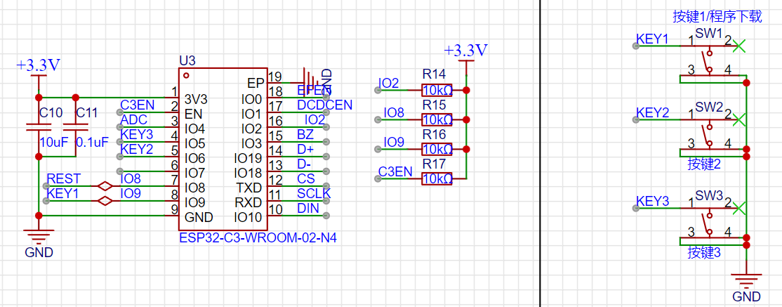
The ESP32-C3 module
requires IO2, IO8, and IO9 pins for startup selection. Please pay attention to the voltage levels of these three pins when the module is powered on. For modules that do not require frequent program downloads, the capacitor used for reset on the C3 enable pin can be omitted. The module's program download uses the C3's built-in CDC serial port. Button 1 serves as both a startup button to enter download mode and a regular button.
Button
1: Brightness setting, 5 levels of fixed brightness and automatic brightness adjustment (automatic brightness illuminates the small TV icon), and a button to enter download mode during cold start.
Button 2: Night Standby On/Off (lights up the switch icon when on).
Button 3: Toggle between displaying temperature/humidity and date (can be set to date display if temperature/humidity sensor is not used).
Software Description
: Project source code links are provided.
The program is quite simple, developed using IDF5.0. Explaining the entire program would be too lengthy, so I will briefly describe the implementation of each functional module. For details, please refer to the source code.
The configuration.h header file allows modification of the Wi-Fi account password (only routers with 2.4G Wi-Fi are required for ESP32-C3 connection), the number of dots for time synchronization, the night standby time with display off, and the exit time.
VFD screen communication uses IO to simulate SPI at a speed of approximately 400K. The scrolling refresh of the time is implemented using the screen's built-in driver IC with 6 CGRAMs. The 1G animation on the screen uses one CGRAM. The icons above the 12 5*7 dot matrix are controlled by AD registers. For details, please refer to the screen's datasheet and source code.
Time calibration comes from Taobao's server using HTTP requests, and timekeeping uses the ESP32-C3's internal RTC. (Aside: Bilibili follower count and weather data are also obtained via HTTP requests.)
Temperature and humidity data are obtained from a separate thermometer and hygrometer (using my open-source wireless thermometer and hygrometer), broadcasting the data. The ESP32-C3 acquires the data via broadcast scanning, using
the nimble protocol stack. Before use, configure Bluetooth > nimble only and the nimble_central_utils component. Both Wi-Fi and BLE are enabled simultaneously. For time synchronization using HTTP requests, broadcast scanning needs to be disabled and then enabled again after synchronization.
The buzzer uses LEDC to generate a PWM driver.
The button driver uses GPIO interrupts; a button press sends a button message to the clock task. Button 1: Brightness setting; Button 2: Night standby on/off; Button 3: Temperature/humidity/date display switch.
The ADC collects the voltage at the photoresistor voltage divider, converting it into 80-240 levels of brightness adjustment.
For abnormal temperature and humidity alarms, the independent temperature and humidity meter requires program modification. The broadcast interval should be changed from once every 5 seconds to once every 100 milliseconds when abnormal temperature and humidity data is detected, allowing the clock to quickly detect the anomaly.
The clock task is an infinite loop that repeats continuously.
The program execution flow is as follows:

Program download (If you don't want to configure the IDF environment yourself, you can ask me to help compile the program corresponding to your own Wi-Fi account and password. The firmware for Wi-Fi account "ABCB" and password "123456789" is provided in the attachment. QQ group: 697752852.
There are two ways to download the program (CH571_BLE_Hygrothermograph.hex is provided in the attachment of the thermometer firmware. Please check the project open source page for the program download method).
Configure VSCode+IDF environment.
Use flash_download_tool to download (download link).
Use ESP launchpad to download online (address link).
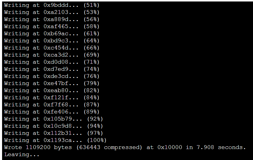
Steps for downloading the program using flash_download_tool
: Press and hold button 1, insert the data cable to connect to the computer, and confirm which COM port it is. The Type-C port on the board is only connected to one side, D+ and D-. If it is not recognized when plugged in correctly, try plugging it in backwards. If it is not recognized at all, check the soldering carefully.
Select the target chip ESP32-C3
, select the download method USB
, click OK
, select the corresponding 3 bin files,
select the COM port recognized by the board
, click Start
, wait for the program to be burned, and then power off and restart.

Use ESP Launchpad Online Download Steps
: Press and hold button 1 to insert the data cable and connect it to the computer. Confirm the COM port. Only one side of the Type-C port on the board is connected (D+, D-). If it's not recognized when plugged in correctly, try plugging it in backwards. If it's still not recognized, carefully check the soldering.
Click

to

see


the physical demonstration .

Design Notes:
Check the soldering for short circuits before plugging it into the computer to download the program.
Solder the other components before soldering the VFD screen. Use something to support the screen during soldering. Be careful when trimming the VFD screen pins
. Do not wash the buzzer and the three buttons with board cleaner.
The clock needs to connect to 2.4G Wi-Fi. The Wi-Fi username and password are written in configuration.h.
If you don't want to configure the IDF environment yourself, you can ask me to help compile the program corresponding to your own Wi-Fi username and password (the firmware with Wi-Fi username "ABCB" and password "1234567890" is provided in the attachment, QQ group: 697752852).
Update Log
2023-11-13: Fixed the bugs of the boot date displaying as 1/0 and the alarm not being triggered when the humidity exceeds 95%.
2024-09-08: Changed low battery detection to percentage battery level; modified the default Wi-Fi username and password in the configuration header file.
2024-09-26: Changed the API for obtaining the time; fixed a time acquisition failure.
Demo video.


 京公网安备 11010802033920号

 C522G102C1CK5CA


