Project Description:
The primary objective of this project is to intelligently upgrade a soft-ball (sponge-like) launcher (Senbailong Gecko 2.0). A device based on an ESP32-Pico-D4 microcontroller is installed on the launcher, featuring a 1.33-inch TFT screen, an integrated IMU (MPU6050), and eight Hall effect sensors. The IMU uses motion sensing to interact with the system, while the Hall effect sensors, in conjunction with magnets, detect ammunition load and chamber status. The ESP32's integrated Bluetooth and Wi-Fi allow for interaction with other systems and data reporting.
(Bilibili video: I made a smart gun and developed a matching smart application, something you probably can't even play in games_Bilibili_bilibili)
Features include: ammunition load detection, chamber and firing detection, shooting stability detection, gun holding stability training, and motion monitoring.
Application

Switching: The device only has a top button and does not use a touchscreen; therefore, it relies on the device's IMU to sense the device's status for operation. Switching applications requires tilting the launcher left or right, swiping the screen once for the preset application, straightening the screen, and pressing the button on the device to enter the application.
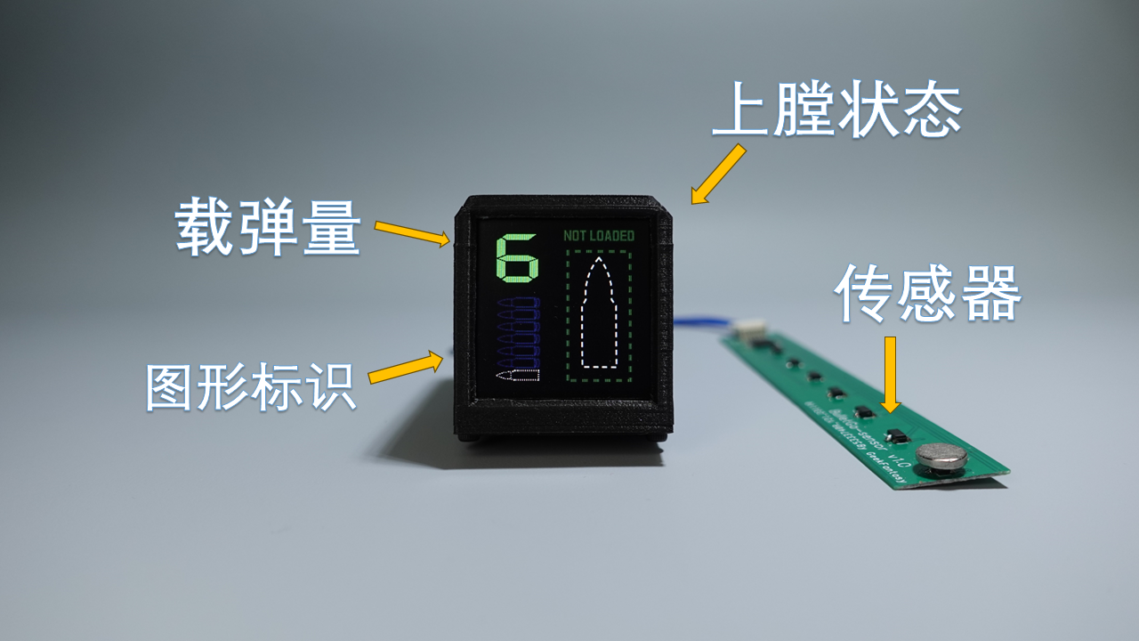
Ammunition Load Display & Loading/Firing Status Detection -- Upon entering the application, the left side of the screen displays the ammunition load and indicator, while the right side displays the loading and firing status. After loading a magazine, the device uses an ammunition load detection circuit to check if a magazine is loaded; if so, it checks the ammunition load again. Simultaneously, the device also detects the loading status. A preset animation effect is displayed when switching between loading and firing statuses. Green indicates no loading, and red indicates a loaded magazine.

Shooting Stability Detection -- This application displays the range of horizontal and vertical direction changes of the device within one second before and after trigger firing, using a two-axis graph to show shooting stability. The flatter the graph curve, the more stable the gun is when firing. This application only displays data; data collection is completed on the ammunition load display interface. The device records the last 5 shots, numbered 1-5, with 1 representing the most recent shot.

Gun Stability Training -- This application is for training purposes. Upon entering the application, a 3-second countdown will occur. After the countdown ends, a target and a green or red dot will be displayed on the screen. The dot changes position according to the launcher's direction. When the dot is near the target's center, it's green, indicating stable aiming; when it turns red, it means the launcher is deviating from its original direction. During training, you need to try to keep the dot centered on the target. The upper left corner of the screen displays the timer, and the upper right corner displays the real-time score. The longer you keep the dot centered, the higher the score, and vice versa.
Motion Status Monitoring – After entering the application, the device starts a Wi-Fi server, and the device screen displays the server address. After connecting to this address with a computer, running the computer-side script will display a real-time 3-axis acceleration curve. The acceleration curve can be used to determine the motion status of the person holding the launcher.
Project Progress
Hardware: Completed, 3D shell files are attached.
Software: Completed Source Code: GeekFantasy/BulletGo (github.com)
Design Principles
The entire project consists of three parts: the main control board, the sensor board, and the programming board, as shown in the diagram below. The main control board integrates an MCU, MPU6050, LCD, and battery management chip, running the main control program. The sensor board integrates an 8-bit GPIO expansion chip, connected to the motherboard via IIC. The eight GPIOs are connected to eight Hall effect sensors for detecting bullet count and chamber status. The programming board integrates a serial port chip and an automatic programming circuit for programming the main control board and for serial communication via a UART bus.

Circuit
Principle:
The main control chip is the ESP32-PICO-D4, a system-in-package (SiP) module based on the ESP32, providing complete Wi-Fi and Bluetooth® functionality. This module has dimensions of only 7mm × 7mm × 0.94mm, occupying a minimal PCB area, and integrates a 4MB Serial Peripheral Interface (SPI) flash. Therefore, the peripheral circuitry can be very simple, allowing for the integration of more components within a relatively small space. The CP-RX/TX pins connect to the serial port chip for logging and programming. The IO0 and EN pins are connected to the programming board and are used to control the chip's switching between programming and LOG modes. LCD-BL/DC/MOSI/SCK/RES control the LCD display driven by the ST7789. GPIO35 connects to a single button used to enter and exit the application. SEN-INT/SCL/SDA connects to the GPIO expansion chip on the sensor board, which can obtain the ammunition load and detect whether it is chambered. MPU-INT/SCL/SDA communicates with the MPU6050 for motion-sensing interaction in the user application. The

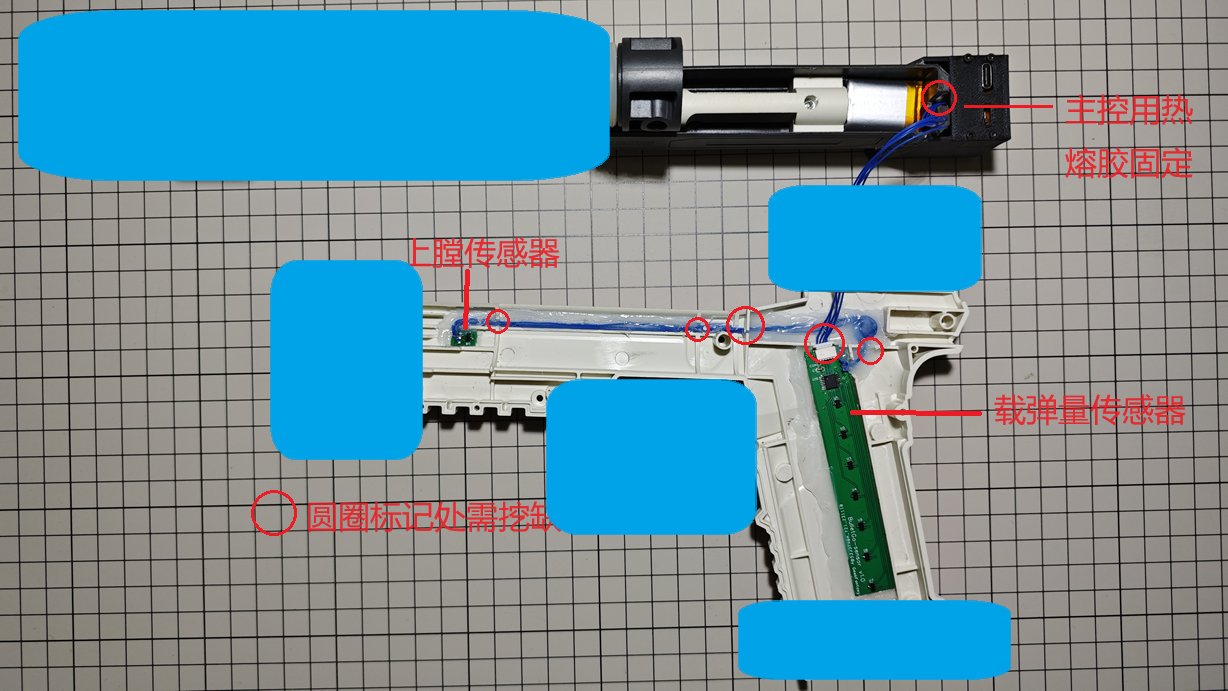
ammunition load and chamber status detection circuit
is located on the sensor board, mounted on the side of the magazine in the launcher. To reduce the number of lines with the main control board, an I2C interface GPIO expansion chip, NXP's PCA9554PW,118, is used to expand 8 GPIOs, each connected to one of 8 Hall sensors. Seven of these Hall sensors are aligned with the magazine load positions 0-6. A circular magnet is fixed on the magazine feed plate to trigger the Hall sensors at different positions. As the ammunition load decreases, the magnets move upwards sequentially, triggering Hall effect sensors at different positions. The PCA9554W reports the GPIO status, allowing the main controller to acquire the ammunition load. Another Hall effect sensor, located at the bolt catch, senses the magnet mounted on the bolt to determine if it is chambered.

Due
to limited space on the main control board, the programming board is handled independently, primarily for program burning and serial communication. A CP2102, along with two transistors, is used to achieve automatic program burning and automatic switching between LOG modes.

Assembly steps:
1. Assemble and test the hardware components as shown in the diagram


. 2. Fix each hardware component to the disassembled transmitter according to the wiring diagram, using hot glue or other adhesives (the blue parts in the diagram are used to cover critical areas; otherwise, it will be recognized as a gun and cannot be uploaded).
3. Install the Hall effect sensor trigger magnets as shown in the diagram.

4. Reassemble the transmitter, test, and you're done.
Device Code:
Firmware code is developed based on the open-source project HoloCubic_AIO; ESP32 code (Arduino): GeekFantasy/BulletGo (github.com)
Materials and Assembly:
PCB: 3 circuit boards: Main_v2.1 (1.2mm thick), Prog_v2 (1.2mm thick), and Sensor_v2 (0.6mm thick or FPC).
Screen: 1.33-inch 240x240 LCD, ST7789 driver, soldered 12-pin bare screen (purchased from Taobao - Zhongjingyuan Electronics)
. Connection Cables: The 3 circuit boards are connected via interface terminals; the terminal connection cables need to be made by yourself and can be purchased from JLCPCB.
Battery: 3.7V lithium-ion battery, model-902030. 500mAh (Thickness: 9mm, Length: 30mm, Width: 20mm) - Please purchase separately (the one I previously purchased is no longer available).
Soft Egg Launcher: All devices need to be integrated into the Gecko 2.0 Soft Egg Launcher. You can purchase it yourself on Taobao by searching the keyword: Senbailong Gecko Launcher 2.0.
Main Control Shell: Needs to be printed separately; see attached model.
Firmware Burning:
1. Using IDE for programming: The program is developed using PlatformIO. You can download the program, compile it, and then directly program it.
2. Using ESP32 programming tool: To be provided later.
Notes:
When prototyping, please pay attention to the board thickness: Main_v2.1 1.2mm, Sensor_v2 0.6mm FR-4 board or use FPC (reinforcement is not required). Boards that are too thick will not be able to be installed.
Currently, the connection between the sensor and main control components is not specially treated, and the wiring harness will be exposed. Those who mind this can wait until a solution is available before replicating.
Reference projects:
Zhihui's HoloCubic (link),
ClimbSnail's HoloCubic_AIO (link)


 京公网安备 11010802033920号

 XC6204D06BDL


