Based on suggestions from experts in the comments section, the version update
increases the line width as much as possible (it couldn't be more than 5mm due to component spacing limitations), and all AC signal lines have exposed copper for easier soldering later!

Project Idea:
The USB night light controller I open-sourced a couple of days ago truly gave me a taste of the fun of smart homes, especially when a friend says they forgot to turn off the lights! I simply used my phone to remotely turn off the night light. You could say that as long as I'm in China, I can remotely control my night light from anywhere with internet access.
As the saying goes, everyone has desires (greed). A night light is just a small light; I want to control the lights in my house, and even the switches of appliances like water heaters, induction cookers, and rice cookers.
So, today I'm sharing a device that can control 220V switching—an AC circuit breaker.
Warning: 220V is high voltage; please take precautions when replicating to avoid accidents.
Control Principle:
To use low-voltage DC devices like WiFi or Bluetooth, you must use an important component—a relay.
Why can a relay control 220V or even higher voltages? Below is a schematic diagram of the internal structure of a relay:

As you can see, the interface contains a coil, an iron core, an iron rod, a spring, and two contacts.
It utilizes the principle of electromagnetism learned in high school physics: when current (usually direct current) is applied to the coil, the iron core in the middle of the coil generates a magnetic force, attracting the iron rod above it. At this time, the contact of the iron rod will contact the contact below, connecting the alternating current and lighting the bulb. When the power to the coil is cut off, the spring pulls the iron rod back up, the contact above it connects, the bulb circuit is broken, and the bulb goes out.
Relay Selection:
There are many different types of relays on the market. How do you choose the right relay for your needs? Generally, the following parameters are prioritized:
maximum switching voltage and maximum switching current.
Rated drive voltage: 3.3V, 5V, 12V , 24V.
Switch types generally include: normally open, normally closed, and variable-
voltage. The size
and maximum switching voltage determine the electrical appliances that the relay can control. In real life, the highest power appliance I've seen is a 3500W water heater (220V 16A). Therefore, in this project, the relay should have a switching current of at least 16A. Because relays have relatively high power consumption (ranging from tens to 200mA), the relay cannot use 3.3V to ensure the WiFi module can work properly, so a 5V relay is chosen. Considering that the circuit breaker only has open and close functions, a normally open switch type is sufficient. Smaller size is better.
In LCSC EDA, a suitable relay was found: HF115F/005-1HS3AF.
Features: 250V 16A control capability, 5V drive, 2912.7 x 15.7mm.
A suitable

relay drive circuit:
Since the relay is driven by 5V, using a PMOS transistor to control the 5V on/off state is most appropriate. Then, to protect the module's I/O, an optocoupler is added to directly achieve power isolation.
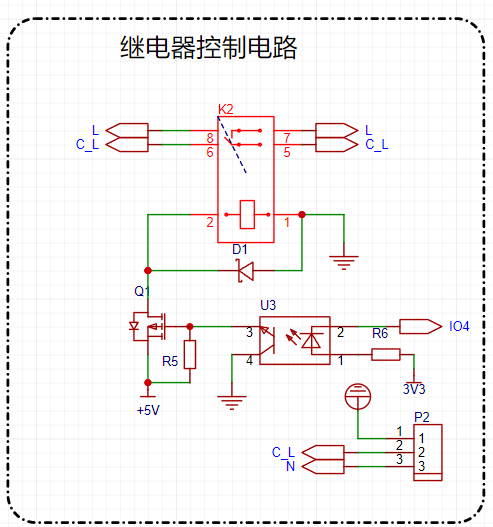
Power supply selection :
Since it controls 220V AC, the power supply can directly use 220V AC, eliminating the need for an external power adapter to provide 5V. The project directly uses an AC-DC converter module, converting 220V to 5V with a 700mA current, which meets the requirements of the module and relay. Module purchase and connection:

Wiring interface selection
. The project's wiring idea is to eliminate the need for screws and enable quick wiring. When making a light controller years ago, I discovered a quick-connect connector:
a pin-type fixing, easy to solder. Rated
current 32A, voltage 400V.
No screws required.
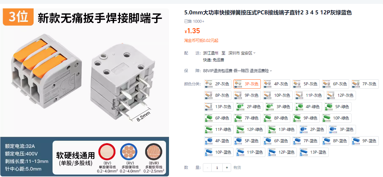
The corresponding LCSC EDA component is DA-803-3.5-3P.

After soldering, wiring can even be done with one hand.

Surge protection circuit :
To prevent damage from lightning strikes, I copied a surge protection circuit from Baidu. Please do not refer to my surge protection layout, as I don't understand the key points. If anyone has expertise, I hope they can offer suggestions.
Other circuit
modules and programming interface reservations:
I chose the Ai-WB2-01M module from Anxinke. This module can be soldered upright, supports 2.4G WiFi, and has low-power BLE, making it ideal for smart home devices like circuit breakers. The circuit is also simple, requiring only a simple power supply to operate.

More information can be found on the official Anxinco docs website. The Anxinco Ai-WB2 series module programming
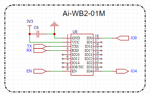
interface (serial port) is reserved by adding test points directly to the PCB. The test point size is 1mm.

After board fabrication, wire bonding or programming pins are used to complete the program programming and debugging.
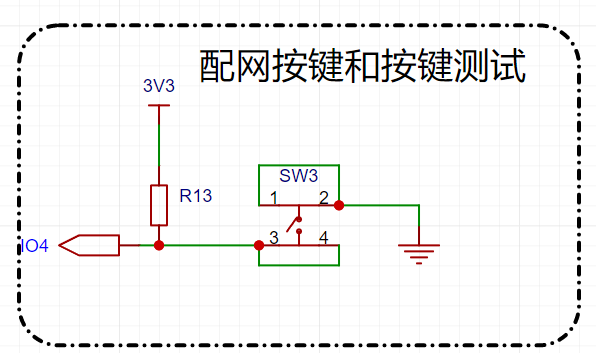
The network indicator

lights, relays, and test buttons are used
to test whether the relays are functioning correctly when no module is soldered.
Features and Functions:
WiFi Direct Control
; Supports Remote Control (requires a remote MQTT server);
Rated Control Voltage: 250V AC; Rated Control Current: 16A
; Network Indicator
; Supports Anxinke IoT WeChat Mini Program Network Configuration : Network
Configuration Method
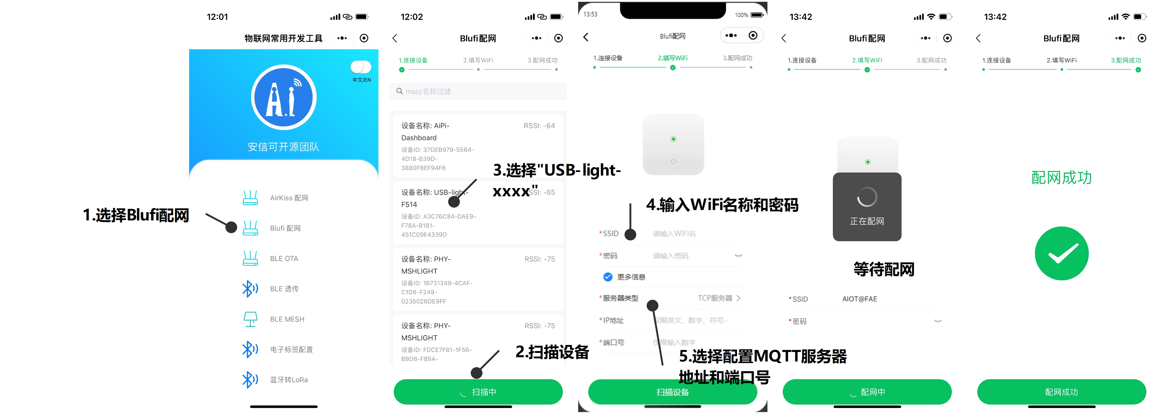
: Press the reset button repeatedly 5 times (with approximately 1 second intervals between each press).
After the network indicator flashes, the network configuration is complete.
Open the WeChat Mini Program and search for "Anxinke IoT"
to enter the Blufi network configuration interface. Click "Scan Devices"
and find a device named "220V-Switch-xxxx".
Click "Connect", enter the WiFi name and password,
click "More Information", and select "MQTT Server" (only needs to be configured once).
Enter the MQTT server address and port number (only needs to be configured once). After entering the information,
click "Configure WiFi ".
Wait for the network indicator to stay on until the network configuration is successful. Lighting
Control: Display cabinet lighting
source code and
3D shell. I only drew a simple sketch of the 3D shell and sealed it; due to time constraints, screw holes were not designed.

All the source code and shell are available in the Gitee remote repository: https://gitee.com/seahi007/HaDevice/tree/main/project/220V-switch.
The
above is either a typo or a genuine error: It controls the most basic function of a light indicator switch, with a maximum control of 16A 250V, allowing it to control appliances up to 4000W, including refrigerators, air conditioners, water heaters, induction cookers, rice cookers, etc. In a company setting, it could also… allow HR to implement access control for switches (that's inhumane!), basically, HR could control the power to all air conditioners, preventing them from being turned on without permission.


 京公网安备 11010802033920号

 240-381RMT25-24SCPGHN


