Preface: A long time ago, when I first used a soldering iron, I wondered why soldering irons are so long now. Soldering already makes my hand tremble a bit, and being so long makes it even worse. Plus, they're bulky and inconvenient to carry, and they heat up slowly. So I wanted to make my own small and convenient soldering iron.
This is an ultra-small digital display temperature-controlled soldering pen, melting solder in 3 seconds, with automatic temperature control, a full-color digital display, and an ultra-small size. It's even slightly smaller than a regular ballpoint pen.

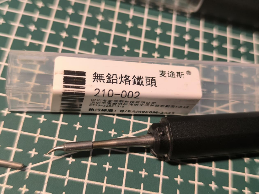
The recommended soldering iron tip is the imported JBC-C210. The domestic C210 tip can also be used.
Basic parameters:
Power supply: Type-C (5V-2A)
Power: 10W
Temperature rise rate: 3~4S (5V-2A 300℃)
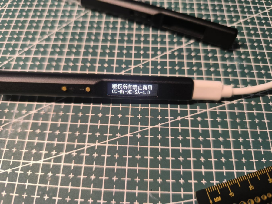
Open source license: CC-BY-NC-SA-4.0 (Commercial use is strictly prohibited; infringement will be prosecuted)
Workflow diagram:
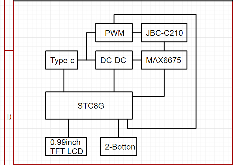
Main controller selected: STC8H8K64U-QFN32 (Program runs at IRC frequency 11.0592MHz)

To minimize circuit board size and space, a QFN-32 package was chosen.
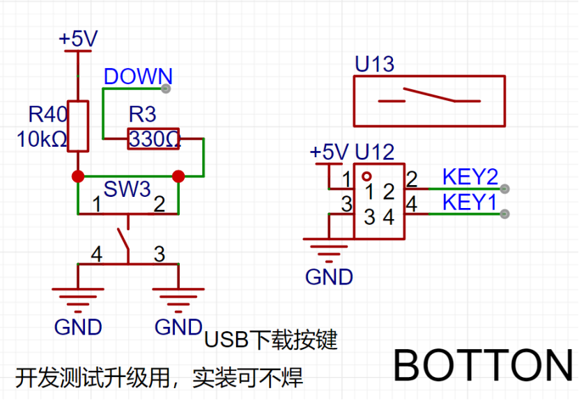
Development notes: Initially, the plan was to use the STC32G12K128 model, programmed with a C251 microcontroller. However, testing revealed limitations in writing TFT refresh programs with the C251 (compatibility errors). Therefore, an STC8H was downgraded. Initially, the pin configuration wasn't carefully considered. When downgrading from STC32G to STC8H, special attention must be paid to the P1.2 pin. This pin is different between the two chips, and in the STC8H-QFN32 package, this pin cannot be set as an output in the program; setting it as an output will prevent the chip from powering on. For ease of debugging, the program downloads via USB, communicating directly with the computer through P3.2 to enter USB download mode (onboard download button).
The temperature controller uses the MAX6675 (also to save space and eliminate the need for analog peripheral circuitry, but at the cost of a slower temperature sampling speed).

In the JBC-C210 soldering iron tip, because the heating wire and thermocouple are connected in series, the heating wire must be energized during heating. To prevent high voltage backflow into the MAX6675 thermocouple sensing pin, which could burn out the MAX6675, a buffer clamping circuit needs to be added to the T+ signal line to limit the maximum voltage of this pin (all pins of the MAX6675 can withstand 3.3V). The program must stagger the heating and temperature measurement periods! Additionally, the MAX6675 temperature conversion process requires approximately 200ms of conversion time (this requires ensuring that each temperature data conversion in the program lasts at least 200ms, otherwise no data will be generated).
The microcontroller queries the MAX6675 for the temperature, but before the MAX6675 finishes calculating, the microcontroller queries again, and the MAX6675 recalculates. Initially, this was the reason why no data was generated.

Procedure: Heat for a period of time, then disconnect the power and wait for discharge. Measure the temperature to determine if heating needs to continue. If yes: continue heating; otherwise: stop heating.
The heating time also serves as the conversion time for the MAX6675 to the previous temperature data, improving program efficiency.
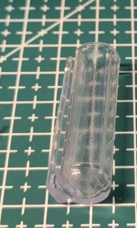
Regarding the soldering iron heating element:
I couldn't find any information about the JBC-C210 online, not a single piece of information. Later, I accidentally discovered that there were domestically made C210 soldering iron elements,
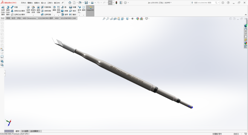
but still no information. So I bought two heating elements online and measured the pin definitions. I then created a 3D model of the soldering iron element based on the actual product for assembly and design simulation (modeling file attached).
After three board modifications, I measured the pin definitions (I'm not sure if they're correct; if anyone has information, please reply in the comments).

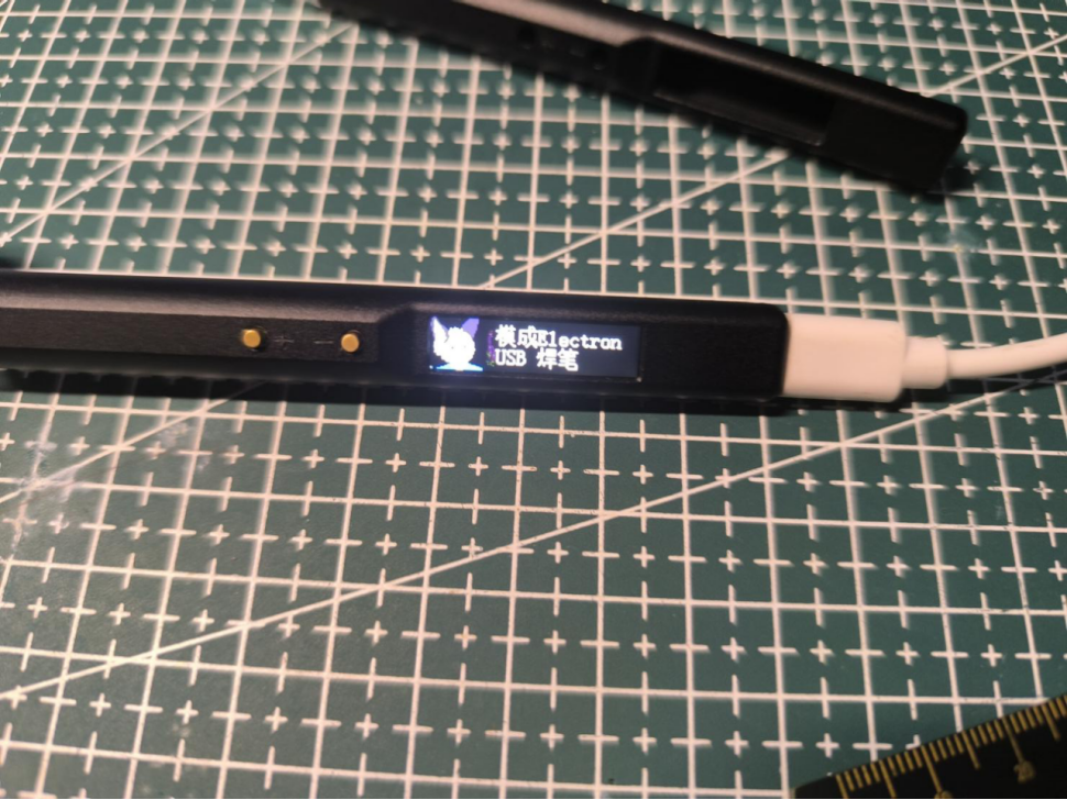
Regarding the screen:
The screen is a 0.99-inch SPI interface TFT-LCD screen (control chip GC9D01) with a resolution of 40*160 RGB full color.
Note: The area with the number 6 in the middle is a dead pixel on the screen, unrelated to the program display. (I was quite unlucky; I bought two screens for testing, one screen's ribbon cable broke due to excessive bending, and the other screen had a dead pixel upon power-on.) The new one hasn't arrived yet, so I can only use the one with the dead pixel for testing.
When purchasing the screen, choose the plug-in model. When plugging it in, the gold fingers of the ribbon

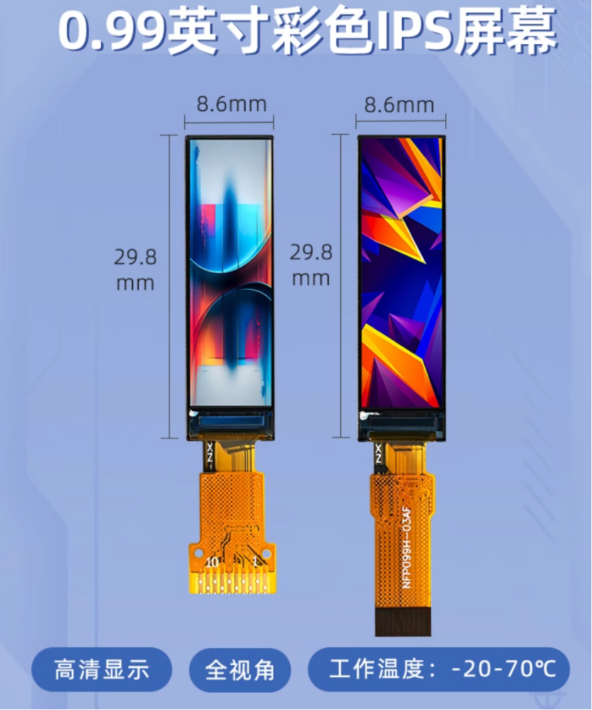
cable should face upwards. The circuitry is straightforward; it's ready to use immediately after plugging in. (I've retained the backlight circuitry for future program upgrades to include sleep mode.)
Screen link:
https://item.taobao.com/item.htm?spm=a1z09.2.0.0.13462e8diktIQE&id=677743417274&_u=h20292vc2r95f1&skuId=5076130632004
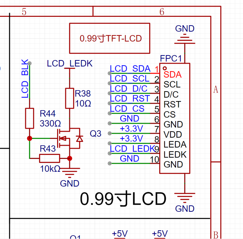
The value of resistor R38 affects the maximum backlight brightness; the minimum value should not be lower than 10Ω, as a lower value may cause burnout.
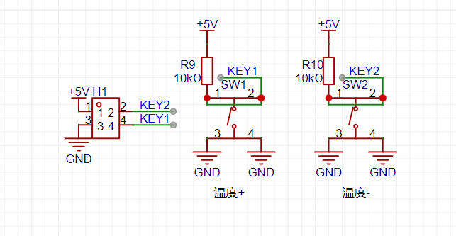
Regarding the buttons:
Please pay special attention here: LCSC serial number: C318886 (Only this model has the correct button height; many other models I bought before didn't have the right height.)

The download button (SW3) doesn't need soldering.
Regarding the PCB:
Initially, the first version was designed as a 4-layer board due to current carrying capacity considerations and the desire to implement power detection and fast charging. However, the actual cost was quite high, and the measured voltage drop across the traces was significant (we later considered thickening the traces and changing the design). The second version removed unnecessary functions and optimized the circuitry and traces, successfully converting it to a 2-layer board. When prototyping the PCB, ensure the board thickness is 0.8mm; otherwise, the casing won't fit.


Regarding the casing:
The casing itself
is made of aluminum alloy and requires CNC machining. 3D printing is not possible here, as the heating element of the soldering iron will melt the 3D printed parts during operation!
Shell Machining: The shell is machined by JLCPCB
using CNC machining parameters: aluminum alloy - 6061 GB/T 1804-2000 m grade Ra3.2.
Surface treatment is: ordinary anodizing - black - matte (this is not a necessary parameter and can be customized).

Solidworks Modeling


Pen Cap Machining:
I used JLCPCB SLA resin to print the pen cap, but in actual testing, the resin structure strength was insufficient. If it is a version with a hook, the hook itself is relatively fragile. However, 3D printing is low-cost, so
it is recommended to use a high-temperature resistant and transparent material.

When using the pen cap, it can also be used as a simple soldering iron stand.
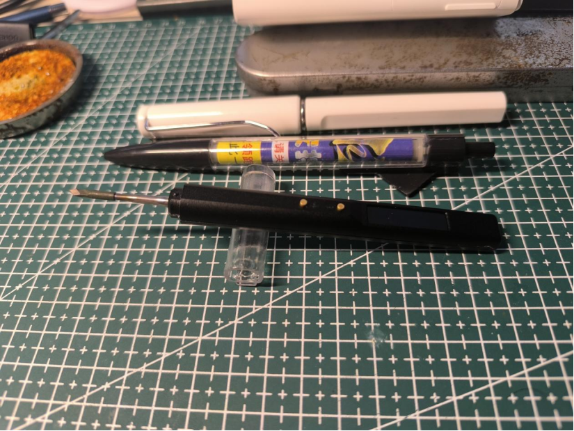
Overall assembly simulation diagram:

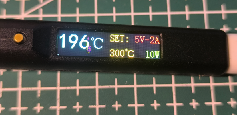
Actual product image:


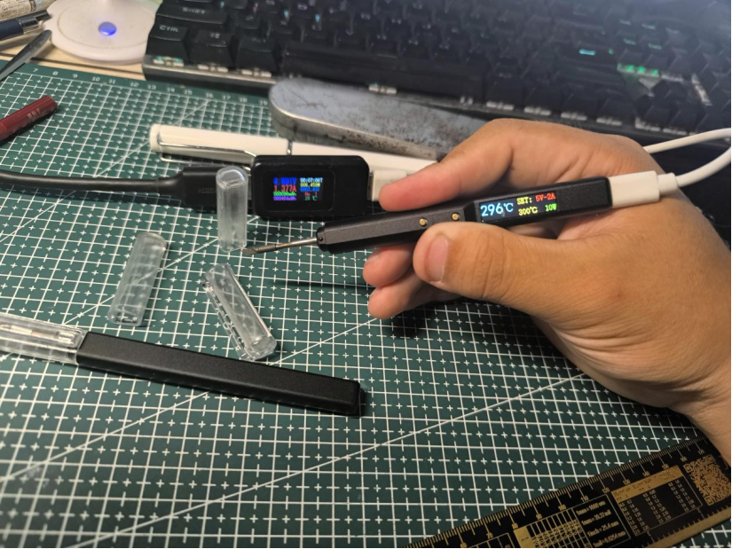

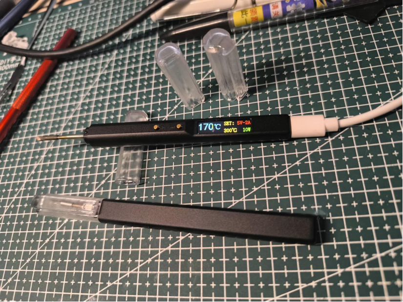


Interaction:
The initial default temperature after power-on is 300 degrees Celsius (the default temperature can be changed in the program, but it is not recommended to exceed 400 degrees Celsius).
Pressing the + button once increases the temperature by 10 degrees Celsius; pressing the - button once decreases the temperature by 10 degrees Celsius.
Future upgrades and improvements:
1. Add PD and QC fast charging protocol support without increasing the size
. 2. Increase the maximum power from 10W to 100W.
3. Optimize the UI interaction interface and add real-time power change display.
4. Stay tuned.
Test video: https://www.bilibili.com/video/BV1MZ421M7Tr/?spm_id_from=333.999.0.0&vd_source=f2ecf6d07c56387a85d94b5338693a63
The 3D shell and program files are attached.


 京公网安备 11010802033920号

 SD1030-TB


