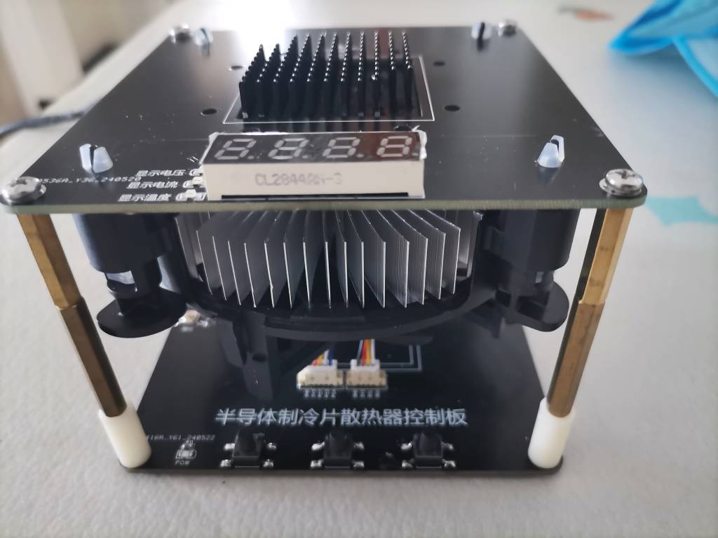
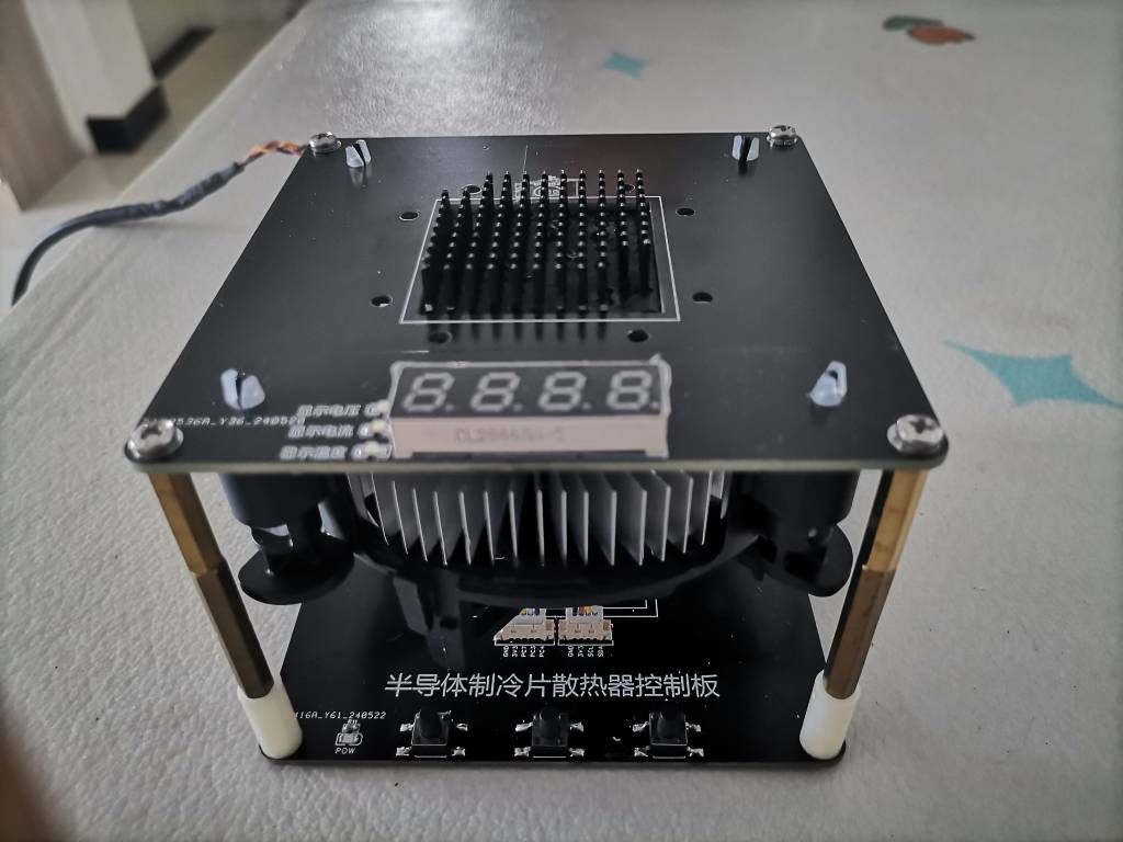
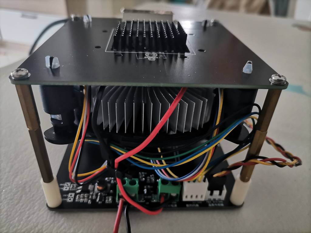
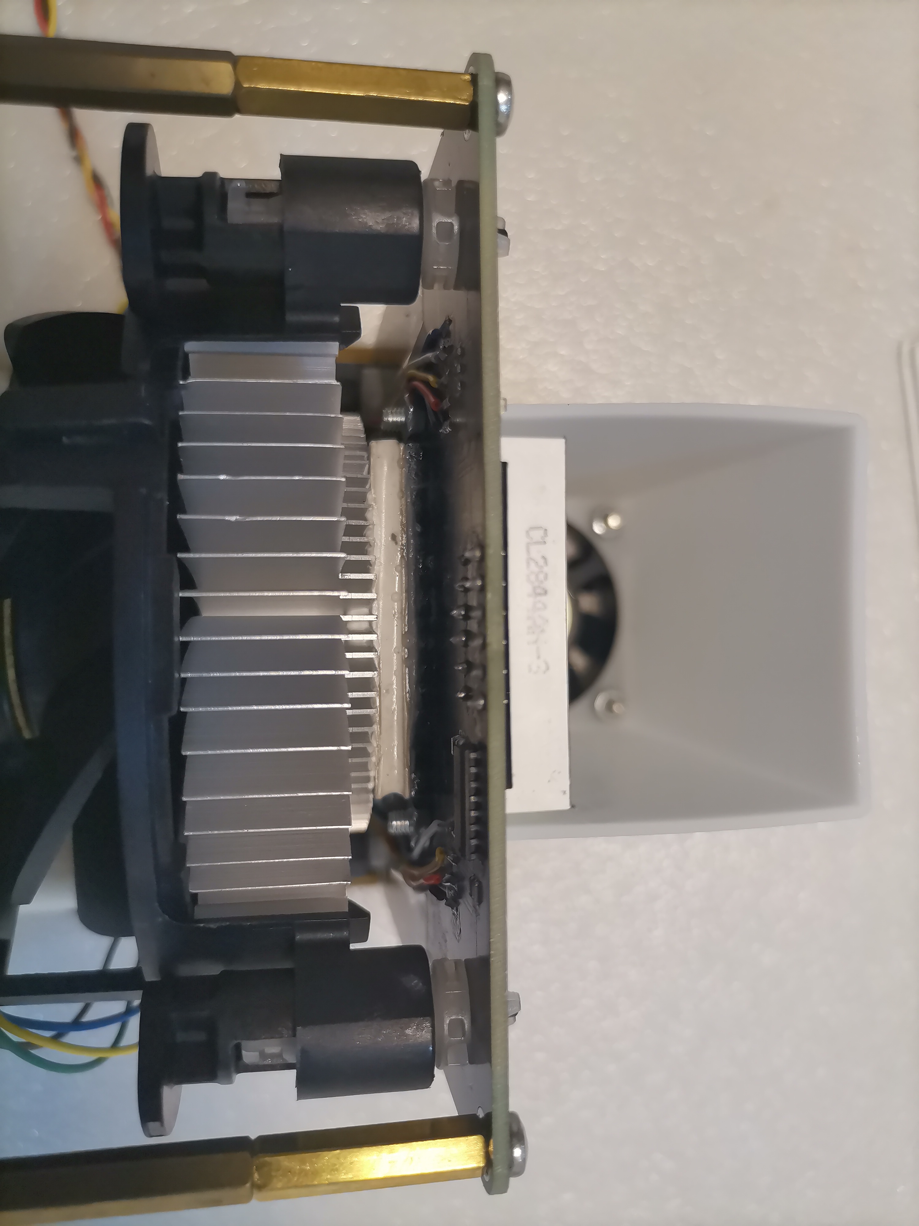
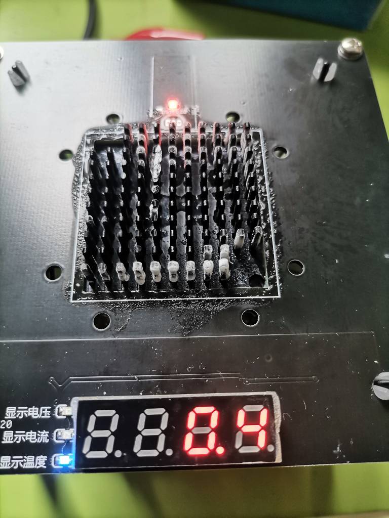
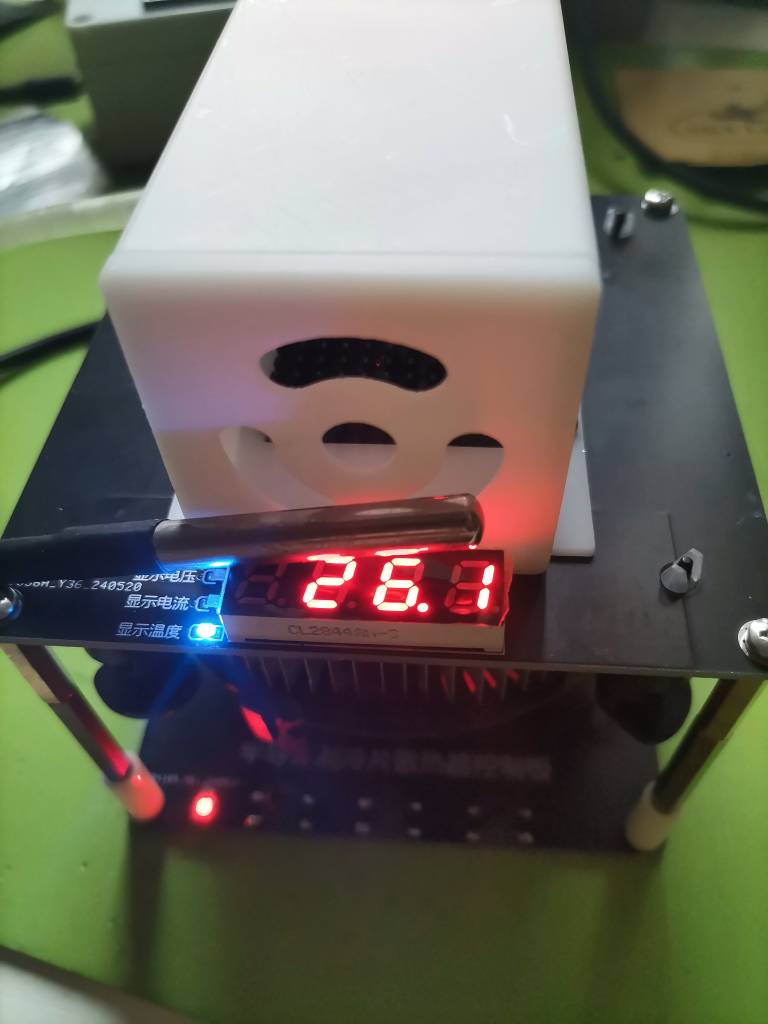
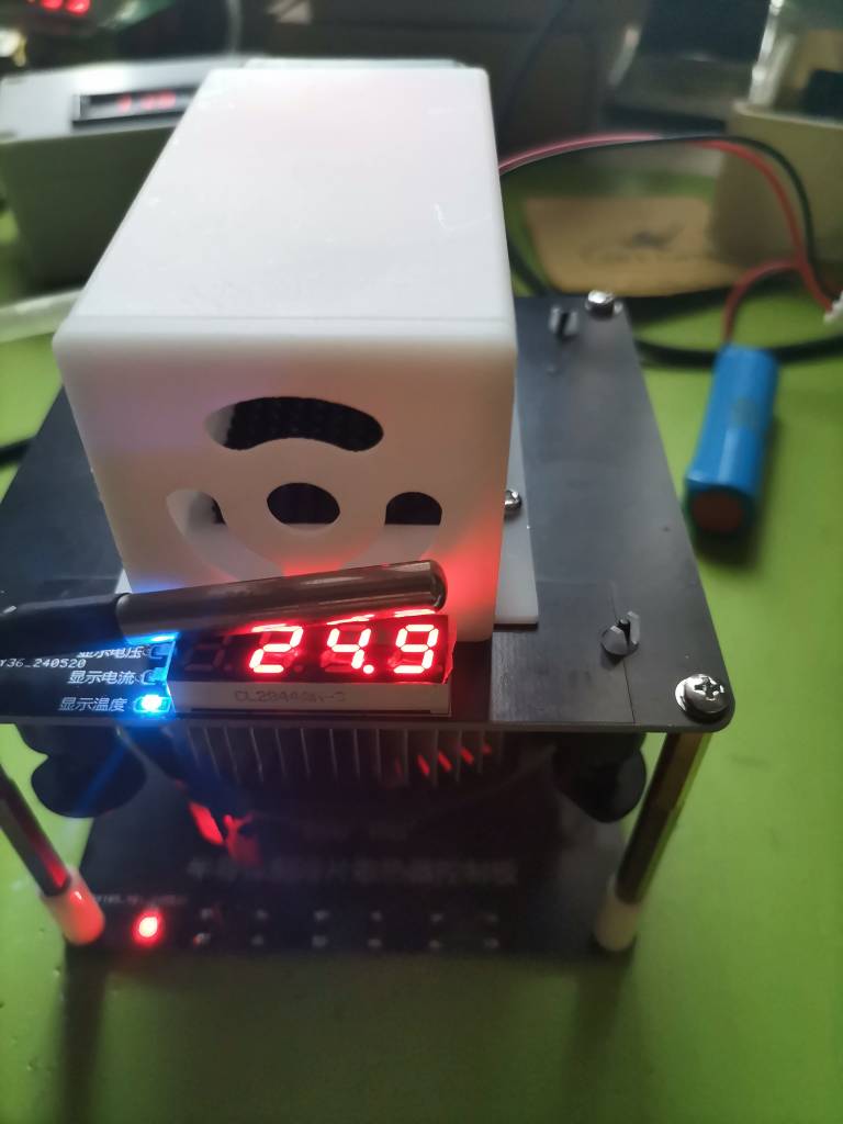
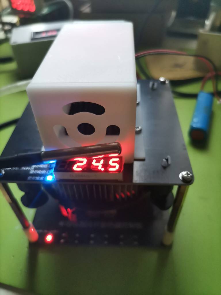
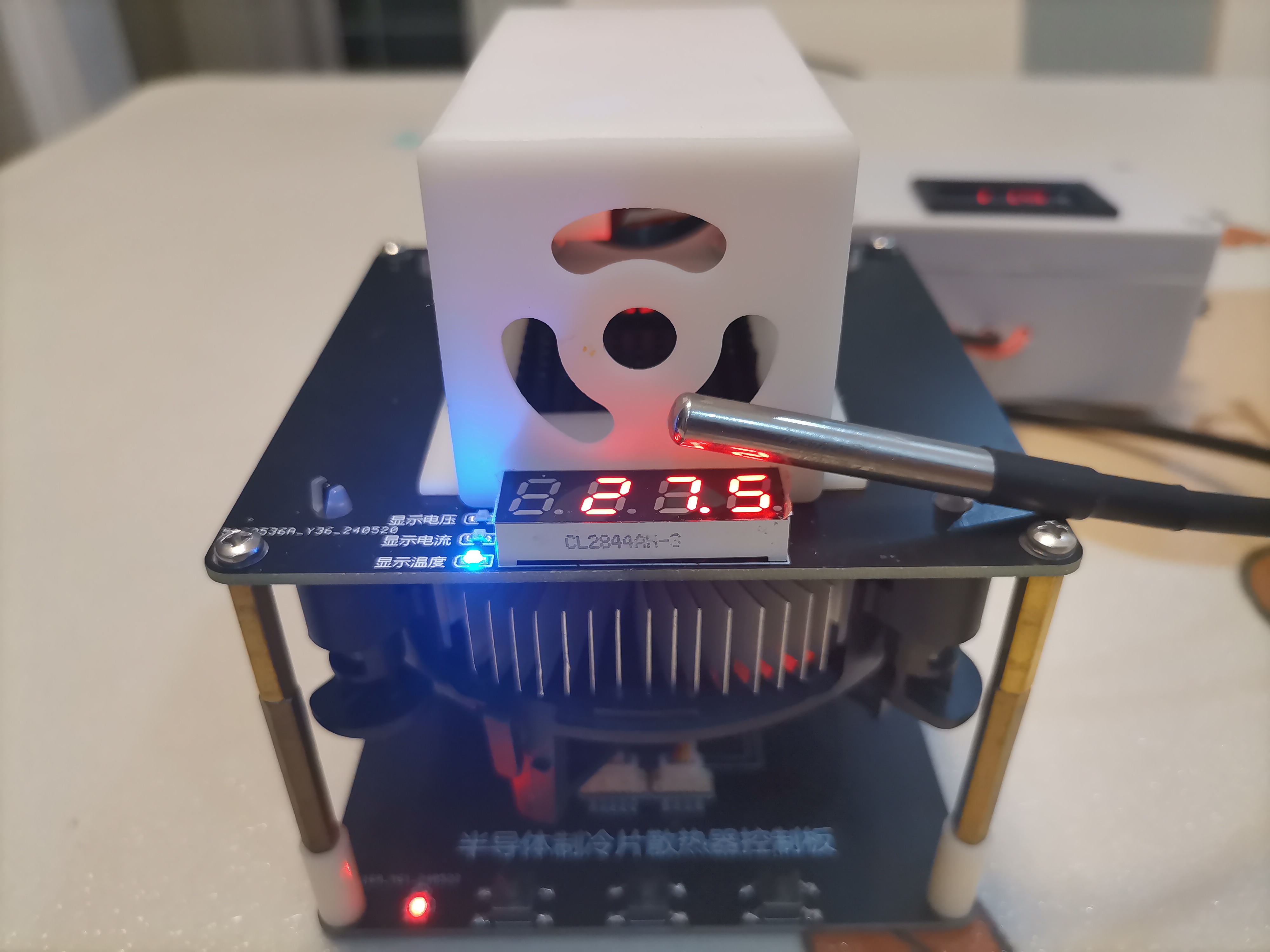
a miniature semiconductor cooling device based on a semiconductor cooling chip. It utilizes a CPU heatsink for heat dissipation and a DS18B20 temperature sensor to detect the cooling temperature, monitoring the output voltage and current in real time. Power supply to the cooling chip and cooling fan is controlled via buttons. The cooling chip
is a TEC1-12706 purchased from Taobao, with a 12V power supply.
The heatsink is the original CPU heatsink that came with my desktop computer.
The main controller is an HK32F030MF4P6.
The digital tube driver chip is a TM1650, powered by 3.3V, and controllable via I2C.
Temperature acquisition uses a DS18B20 with a measurement range of -55°C to +125°C.
The cooling chip's power supply is controlled by a TX40N06B MOSFET, with a drain-source voltage (Vdss) of 60V, a continuous drain current (Id) of 35A, and a power (Pd) of 250W. The MCU is isolated from the MOSFET via an optocoupler.
The heatsink fan is powered by a WST3400A MOSFET.
Current sampling uses an INA180A2IDBVR current-sense amplifier to acquire the output current, employing a 5mΩ, 3W, 2512 package sampling resistor (two 10mΩ resistors were used in parallel on the actual circuit board due to a lack of 5mΩ resistors).
Voltage dividers are used to sample the input (output) voltage.
The power supply section uses a DC-DC buck converter and an LDO linear regulator. The DC-DC buck converter is a ME3116AM6G with an input voltage range of 4.75V-40V (12V in this project) and an output of 5V. The LDO linear regulator is an AMS1117-3.3, used to power the main controller and peripheral devices.
Three I/O ports are provided for external indicator lights, using 1x5P 1.25mm wire-to-board headers.
An I2C interface is provided for connecting an external digital tube or display screen, using a 1x4P 1.25mm wire-to-board connector.
The main control board includes three buttons for human-machine interaction.
and displaying output current. Note that the thermoelectric cooler draws a relatively large current during operation; a high-power power supply is recommended.
Actual measurements show a maximum current of 4.7A with a 12V power supply. The heat dissipation of the thermoelectric cooler's heating surface significantly affects the cooling effect; the cooling fan generally needs to run at full speed to control the heat generated by the radiator. An additional airflow guide was added, primarily to use a small fan to blow air over the aluminum alloy heatsink above the cooler (for cooling), producing cool air. However, actual testing showed that the effect was not very good; the blown air only lowered the room temperature by about 2 degrees Celsius. A horizontal duct was added to the airflow guide for introducing mist. The initial goal was to deliver the water mist from the atomizer through a conduit to a cooling tube, then cool the mist using a cooling plate before blowing it out as cold air. However, the actual effect was not significant; the water mist formed by the atomizer condensed into droplets in the conduit and could not be delivered to the cooling tube. (Actual product image)
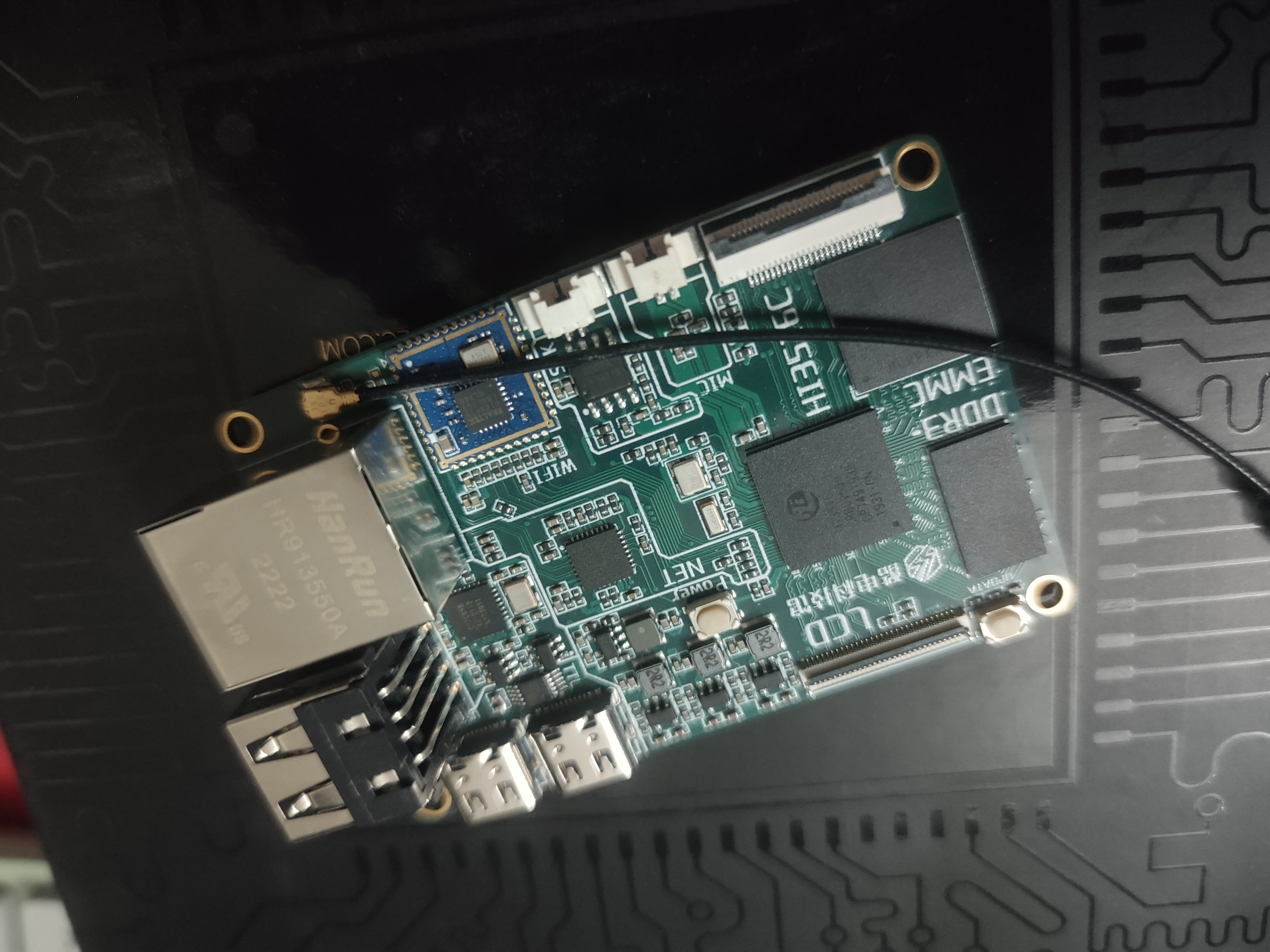
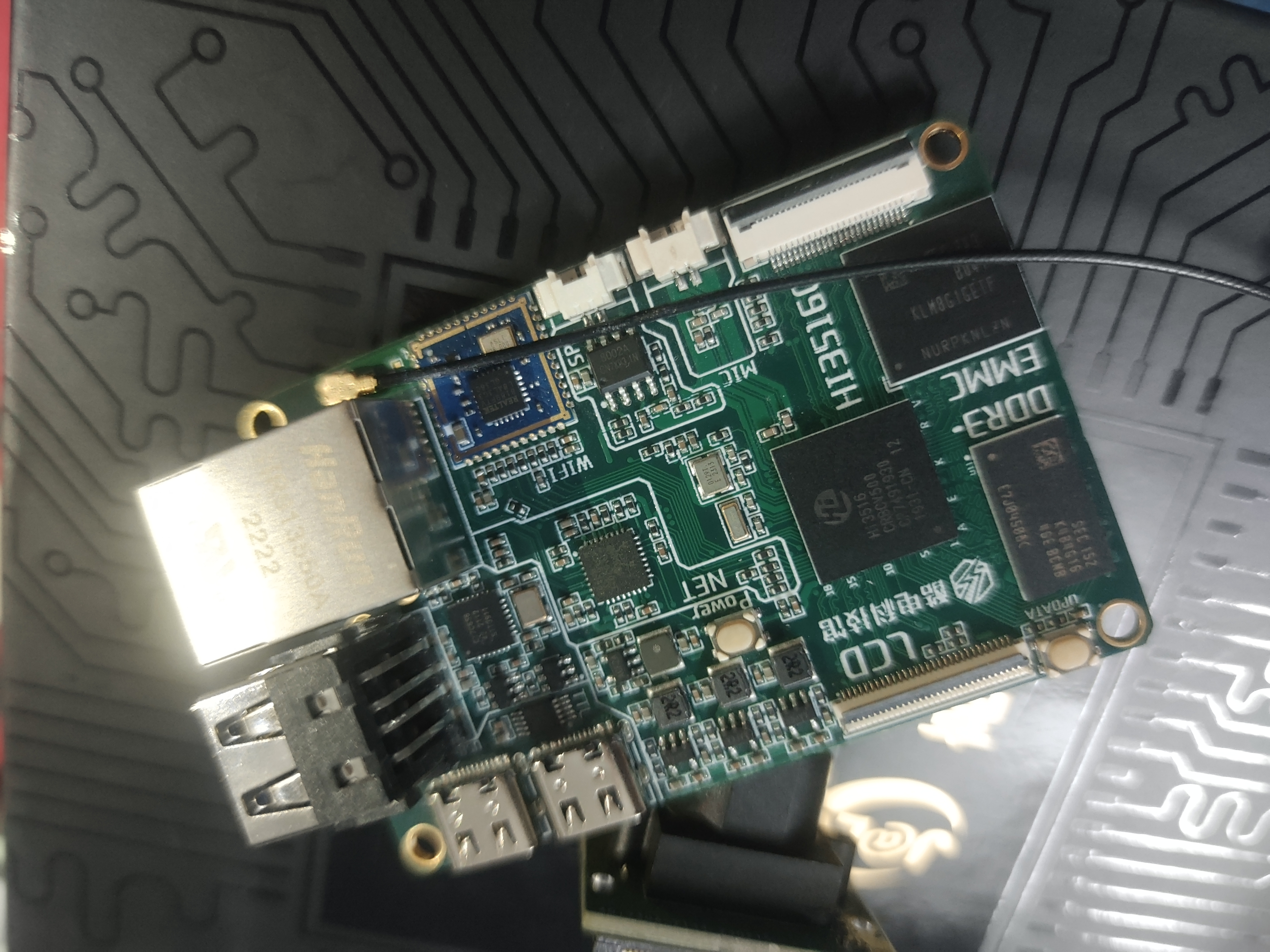
The Hisilicon HI3516CV500 development board/dashcam/electron microscope features a MIPI display and an IMX327 camera, and utilizes Linux + QT/LVGL + MPP libraries to achieve video capture and display, video encoding and storage, and GUI display functions.
This is a voice chat with a cat on ChatGPT.
For this dish of dumplings wrapped in vinegar, a small high-speed electronic load
How many microcontroller pins are needed to make a programmable electronic load? What power transistors and operational amplifiers should be selected? Implement a small electronic load based on the STC8G1K08A.
Parameter Features Description: (Skip the short essay and just read this part)
Design Theme: A compact and simple high-speed response programmable electronic load, constant current mode, interactive via a monochrome OLED screen and touch buttons.
Input Voltage Range: 2.5V~50V (load input voltage when auxiliary power is provided), 4.5V~50V without auxiliary power input.
Maximum Input Current: 4A
Main Functions: Programmable constant current mode, oscilloscope, can operate without auxiliary power, overheat protection, reverse connection protection
. Maximum Continuous Power (25℃ environment): 6W (without heat sink, air-cooled) / 10W (with heat sink, air-cooled) / 22W (with heat sink, water-cooled)
Peak Power: 50W
Full-range Current Rise and Fall Time: 0.5uS (0.1A~4A) (square wave debugging state)
Load Input Mode: USB input + Load interface input
Power Supply Mode: USB auxiliary power + Load power supply
manufacturing cost: Components approximately 50 yuan, casing approximately 20 yuan.
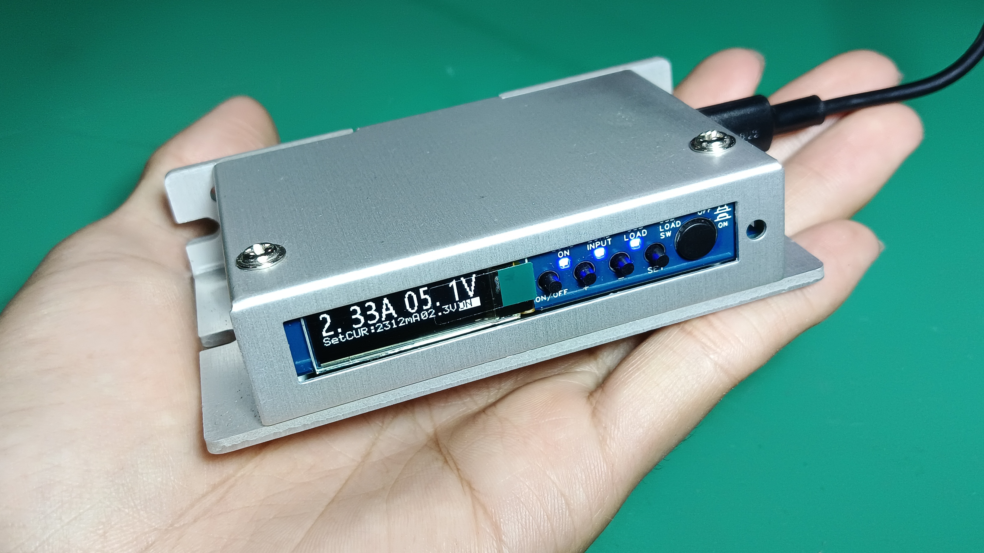
Finished product image:
The following is a rambling short essay:
One day, a question suddenly occurred to me:
How many microcontroller pins are needed at a minimum to make a simple programmable electronic load?
A simple count (after countless internal debates between simplicity and complexity (▼ヘ▼#)):
1 PWM for DAC (using a DAC chip is more sophisticated and faster, but no, no, it's supposed to be simple),
1 internal ADC for voltage acquisition (using an ADC chip is more sophisticated with higher bit depth and speed, but no, no, it's supposed to be simple),
1 internal ADC for current acquisition (using an ADC chip is more sophisticated with higher bit depth and speed, but no, no, it's supposed to be simple),
2 IOs for IIC monochrome OLED screen control (making a color screen would be so cool and colorful, but no, no, it's supposed to be simple).
One ADC for button reading (how convenient and cool would it be to have a keyboard, touchscreen, or knob interaction? No way, it's supposed to be simple),
that makes six in total.
Coincidentally, that can be implemented with an 8-pin microcontroller. (Why don't I have any extra pins?! (╯‵□′)╯︵┻━┻)
So, let's use a state-of-the-art STC8G1K08A, isn't that amazing?
Since this electronic load is to be simple, let's also make it compact,
high-speed responsive, constant voltage, constant resistance, and constant power, intelligently networked, and even capable of lighting cigarettes...
(No, no, we agreed to keep it simple.)
Let's set the design goals:
a compact, high-speed response programmable electronic load with only constant current mode, using a monochrome OLED screen and touch buttons for interaction.
For the sake of overall cohesion, I won't choose a shell for the CNC-machined sheet metal acrylic panel; instead, I'll
choose an all-aluminum shell for the motor driver:

this shell has good heat dissipation (it gets very hot to the touch after heating up) and a small size (I can't afford a large aluminum shell, and I can't get a free PCB).
First, let's define the design goals (after five iterations):
100V, 10A (voltage acquisition and heat generation are difficult to handle);
40V, 3A (voltage and current have been tested and can be increased slightly);
input voltage range: 2.5V~50V, maximum input current: 4A;
this voltage range is a compromise between circuit complexity and component voltage tolerance, covering common voltages and meeting 1S~11S lithium battery testing requirements.
Moreover, this microcontroller is a true 10-bit ADC; to meet 0.1V measurement, the maximum measurable voltage can only be 50V (with a redundancy of 0.5). (Indicated value).
The current range is a compromise between heat dissipation and high-speed response (discussed in more detail later).
Since some small and DIY electronic loads use a separate 12V power supply, which is not particularly convenient,
a dual power supply mode is used:
USB auxiliary power supply + load
power supply. The auxiliary power supply is used when connected; when no auxiliary power supply is available, it automatically switches to load power supply mode, drawing power directly from the load.
Note: When the load voltage is below 4.5V, an auxiliary power supply with a voltage greater than 4.5V is required.
The auxiliary power supply uses the most common USB Type-C interface, which can be provided by a mobile phone charger or computer.
The USB auxiliary power supply can also be used as a load input (USB load).
The Type-C interface is connected to a 5.1K resistor in the CC port, allowing for a 5V power supply in C2C mode. The board lacks a spoofing function (USB input voltage tolerance can reach 20V).
Using a 5V input voltage as auxiliary power is less ideal than 12V, as
the internal op-amps can only use low-voltage versions, and the output voltage margin is relatively small.
Furthermore, this voltage cannot be directly used to reliably drive MOSFETs, which is one reason why transistors were chosen in this design.
However, the most problematic aspect is the wide input voltage range of 4.5V~50V for auxiliary power. (╯‵□′)╯︵┻━┻
Moreover, considering the difficulty of noise processing (which is manageable but too lazy to do), and the fact that inductive DC-DC converters cannot well adapt to wide voltage ranges (ripple current issues), and adhering to the principle of simplicity
, this version uses a linear regulator.
This means that the auxiliary power supply must be able to ensure the normal operation of internal components at a low voltage of 4.5V, and withstand the dissipation problem at a 50V input.
To this end, this design uses a dual power supply as a compromise:
when connected to USB power, it uses the 5V of USB; when not connected to USB power, it uses the load power supply.
This provides an optional auxiliary power input with a lower voltage when there is a high voltage input, reducing the pressure on the linear regulator.
One of the core components of an electronic load is the load power transistor section.
Currently, most electronic loads use MOSFETs as the main power transistors, and then use operational amplifiers for closed-loop control.
MOSFETs have many excellent features: fast response speed and low on-state voltage. Everyone uses them, so they must be good, right?!
However, I personally believe that MOSFETs are ultimately voltage-controlled resistor devices. It feels a bit too straightforward for constant current applications.
Since this is also an experiment, let's try a more direct solution:
Let's bring out (a dazzling entrance with lights and music): a faucet transistor! (ノ´▽`)ノ♪
Using current to control current, this device seems like a perfect match for constant current circuits! (~ ̄▽ ̄)~
Let's choose a transistor! (。◕ˇ∀ˇ◕) 50V, 4A, seems like a lot of choices!
No! One design principle is: high-speed response! (`゚Д゚´)ゞ An electronic load that doesn't consider response speed isn't a good power supply.
Although response speed is affected by many factors (we're just playing around anyway), the power transistor is a crucial component.
Small-signal transistors can easily reach characteristic frequencies of over 100MHz, and high-power transistors can easily handle currents up to 5A (of course I want them all!).
However, the rated current of small-signal transistors is usually only a few hundred milliamps, and the characteristic frequency of high-power transistors is generally only within 10MHz or even less.
There's no such thing as a free lunch, but there are PCBs
that can be obtained for free. In order to satisfy both speed and current requirements, let's use the old-fashioned method of using powerful transistors:
parallel transistors!
Parallelizing transistors retains the performance of individual transistors in terms of response speed and voltage, but the rated current is superimposed. Of course, leakage current and drive current are also superimposed. Parallelizing transistors
requires addressing current balancing; the inconsistency of individual transistors worsens with increasing quantity.
Parallelizing 40 5551s seems excessive, and the SOT23 package has poor heat dissipation, while the SOT-89's heat dissipation isn't particularly ideal either.
After three days and nights of searching Taobao and LCSC's online store, I finally chose TO-252 (affordable) low-power transistors for paralleling.
Recommended models are 2SD1815 or 2SD669 (better-performing transistors are also acceptable if available).
Although the transistor's nominal rated current is 3A, the datasheet chart shows that the gain begins to decrease after 200mA, and the gain is less than 100 after 300mA

(UTC_2SD669_gain-bandwidth vs. collector current curve).

(On Semiconductor 2SD1815 Gain-Bandwidth vs. Collector Current Curve)
This means that to achieve the best frequency response and amplification (greater than 100x),
a single transistor can only be set to a current of no more than 300mA. Can the unused current be refunded?! (▼ヘ▼#)
Too many transistors would be too much, too few transistors would result in too little total current. 16 transistors are just right, and parallel connection can meet the 4.8A current requirement.
To reduce the impact of transistor mismatch, they are divided into 4 groups for parallel connection.
Since each transistor requires 300mA of output current, the base current must be at least 3mA. This is clearly impractical to directly output to the transistors
using a single op-amp stage. Therefore, a two-stage Darlington configuration is used to meet the output current requirements and reduce the pressure on the onboard auxiliary power supply.
However, the Darlington structure increases the final output saturation voltage drop (by adding the Vbe of one transistor),
so using transistors as the power stage limits the minimum input voltage. This is one of the reasons why most modern electronic loads do not use transistors.
This design omits the low-voltage input range to showcase the current handling capability of transistors.
The second core aspect of the electronic load: the loop control section .
A brief overview reveals that most open-source electronic loads use the TL084 for higher speeds and the LM358 for lower speeds.
The bandwidth of TL082 and TL072 types is approximately 3MHz, while that of the LM358 type is approximately 1MHz.
So, what is the relationship between this bandwidth and the actual final response speed? Which op-amp should be chosen?
Let me share my thoughts, albeit somewhat haphazardly
: We'll start with the most basic black-box analysis of op-amps:
the fundamental formula for an op-amp is: Uo = Ao * (Up - Un)
, where Uo is the output voltage, Ao is the open-loop gain, Up is the positive input voltage, and Un is the negative input voltage. Let's
rearrange the formula: Uo / Ao = (Up - Un) .
When Ao approaches +∞, Up = Un, which is what many call "virtual short,"
but I prefer to describe this phenomenon as:
"When an op-amp forms negative feedback, it will try to make Up and Un equal
. "
This phenomenon is most commonly used in simple calculations and is one of the simplification conditions used to construct expressions.
But what if Ao is not +∞? Will Up still equal Un?
In DC conditions, modern op-amps can easily achieve an open-loop gain Ao of over 80dB (10k times), with high-gain products reaching 130dB (3M times).
However, for stability, op-amp designs actively suppress high-frequency open-loop gain, causing it to decrease with increasing frequency.
The rate of gain decrease is faster than the inherent characteristics of the internal transistors, and the rate of decrease is relatively stable (approximately 20dB (10 times) decrease for every 10-fold increase in frequency).
When the open-loop gain drops to 0dB (1 time), this frequency is defined as the op-amp's bandwidth.
So, what if we substitute the condition of open-loop gain Ao = 1 into the basic op-amp formula?
Then we are left with: Uo = Up - Un, where the output equals the voltage difference between the input and output terminals.
In this state, there is no such thing as a "virtual short."
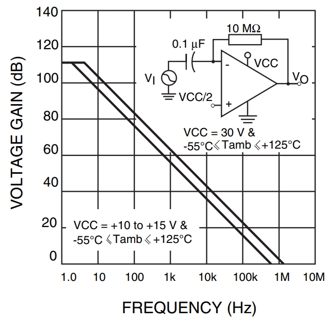
The open-loop gain and frequency relationship of the LM358
are then substituted into a commonly used non-inverting amplifier circuit
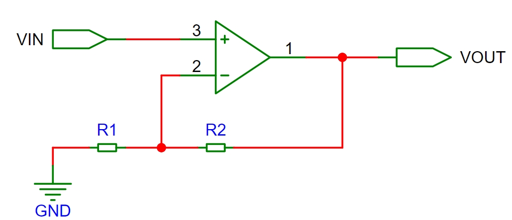
to calculate the relationship:
Up = VIN, Un = (Uo - 0V) * (R1 / (R1 + R2)) + 0V
(the negative terminal voltage equals the voltage division between R1 and R2 between the output and GND).
According to Uo = Ao * (Up - Un),
we get Uo = VIN / ((1 / Ao) + (R1 / (R1 + R2)))
(the output voltage equals VIN divided by the reciprocal of Ao plus the voltage division ratio of R1 and R2).
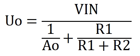
When Ao is +∞, the amplification factor is the commonly seen (1 + R2 / R1).
It can be seen that 1/Ao is the part of the amplification factor that causes error; the smaller Ao is, the larger the error.
Since this error can be written in the formula, there should be a way to compensate for it.
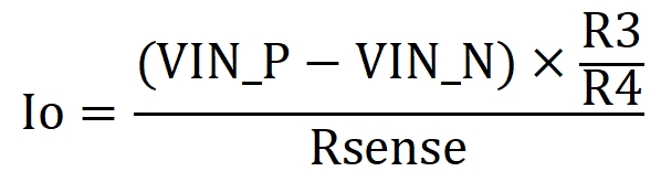
The following is a simplified differential voltage-controlled current circuit used in this design:

In DC, the amplification factor of each stage is relatively easy to derive.
However, in AC, parasitic parameters and the frequency domain characteristics of the devices need to be added, but the main relationships remain unchanged, only the parameters increase.
When R1/R2 = R3/R4, the basic relationship is:
However, in actual negative feedback circuits, we often encounter the following input-output phenomenon:
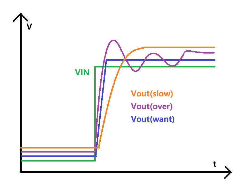
the output is either too fast but overshoots, or too slow but remains stable (╯‵□′)╯︵┻━┻
There are many solutions to this problem, namely loop compensation methods.
The most common method is to perform system zero-pole analysis in the frequency domain and then perform compensation. Many experts have explained this method.
However, frequency domain analysis has one drawback: we generally cannot obtain enough system parameters to build a model.
Furthermore, most labs lack phase-frequency characteristic scanning equipment.
Therefore, in system negative feedback design, time-domain analysis is more commonly used to extract necessary information.
For loop response design, I personally prefer to identify the bottleneck, making faster components wait for slower ones.
First, I confirm the open-loop response of each transmission link to see which component is ultimately hindering the process. Then,
I slow down the faster components and finally strive for impedance matching throughout the entire link.
I believe open-loop characteristics are also crucial in closed-loop circuitry; a poorly understood open-loop characteristic makes closed-loop tuning difficult.
Okay, after this rambling, let's get to the practical part.
First, we measured the open-loop response of the power stage transistor. A 0-3V square wave step input (rise time less than 10ns) was given to the CTR, and the voltage across the current sensing resistor R16 was measured. The
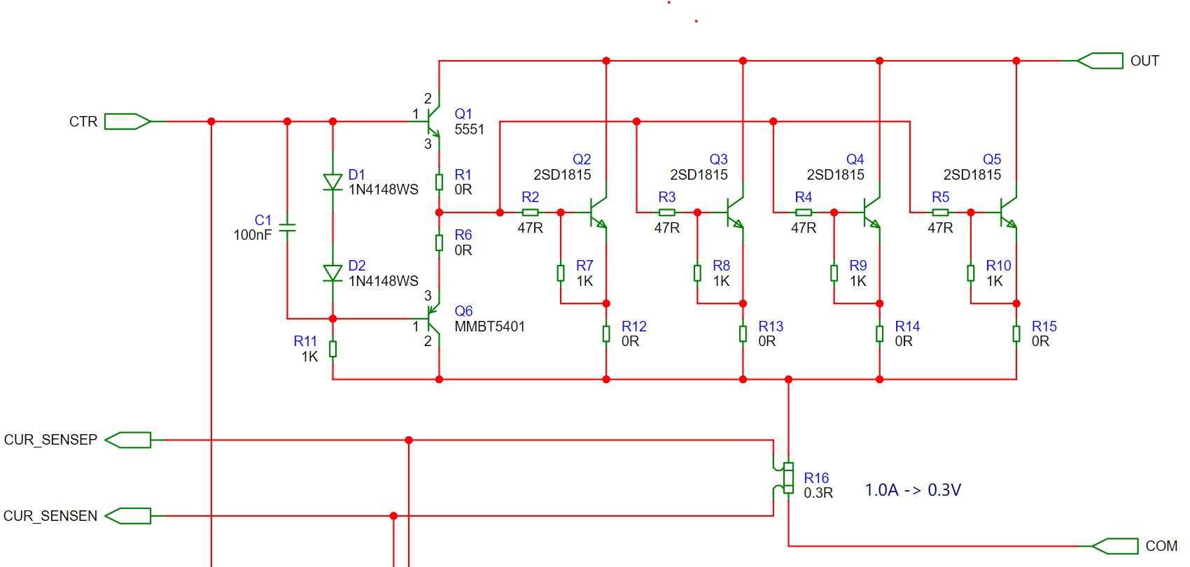
measured waveform
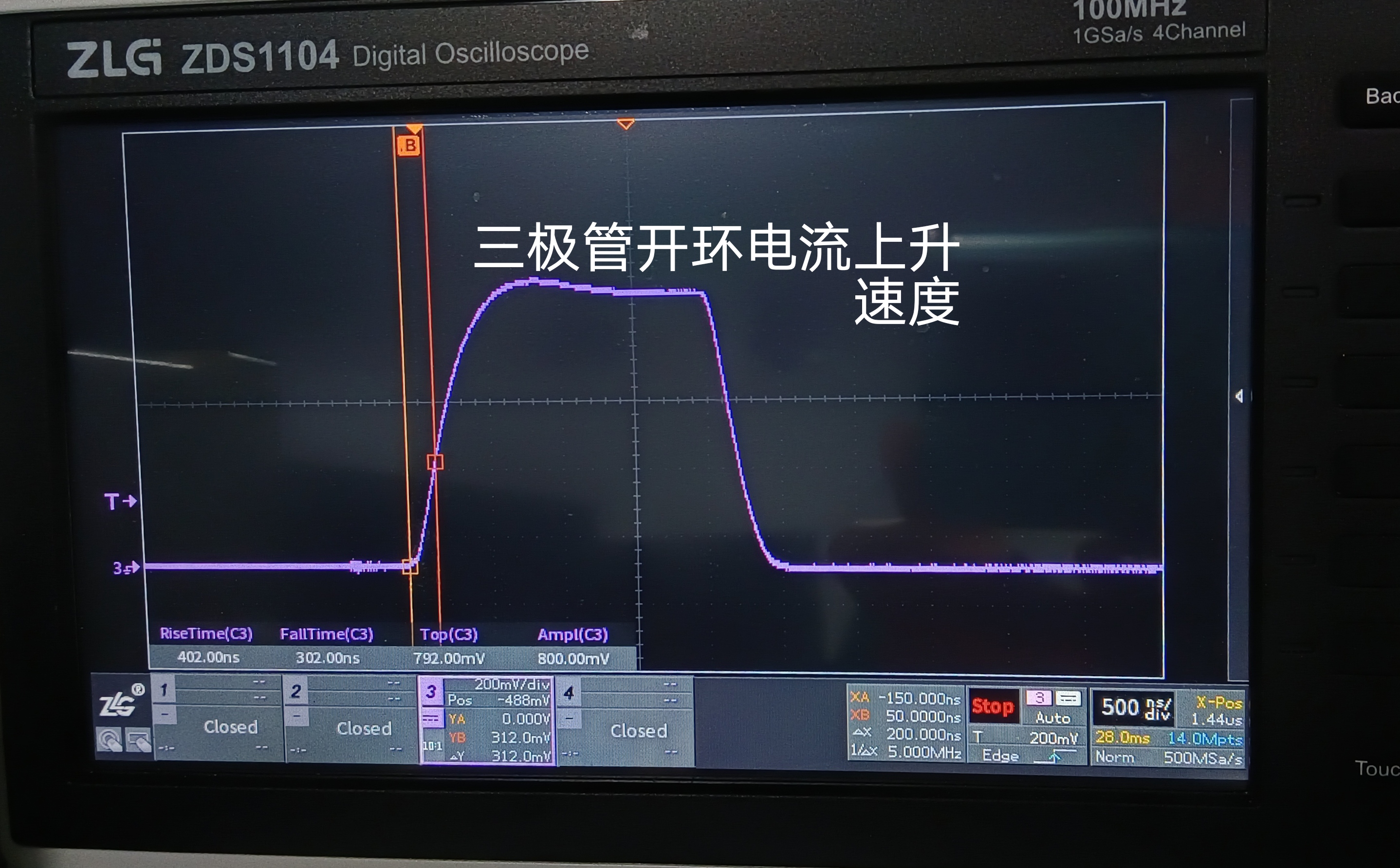
shows that the output current waveform closely follows the input control signal, with little overshoot in the open loop.
Then, we observed that at the required 1A (250mA per transistor), the current rise time is 200ns.
This demonstrates the excellent open-loop characteristic of the power stage; it outputs exactly what is input, with a nearly stable ratio. Therefore, we can proceed with our work.
After obtaining the power stage response, the next step is to select the op-amp.
This raises the question: what bandwidth does 200ns correspond to?
Generally, bandwidth is defined according to the frequency of a sine wave. A sine wave corresponds to a trigonometric function where odd values change and even values remain the same, with the sign determined by the quadrant.
Let's first calculate the frequency corresponding to the desired current slope (1A/200nS):
A is the coefficient on the vertical axis, f is the frequency, the slope is k, and the time is t.
The maximum slope of the function A * sin(2 * pai * f * x) is at t=0. The derivative at t=0 is d = A * 2 * pai * f.
Because the slope at other times is less than this slope, obtaining the maximum slope is equivalent to obtaining the highest frequency component.
Slope: k = A / t = A * 2 * pai * f = 5A/µs, yielding f = 0.796MHz.
Returning to the diagram of differential voltage controlling current above, although the entire differential amplifier circuit has a ratio of R3/R4, the
actual amplification factor of the op-amp is actually the non-inverting side, which is the amplification factor produced by the attenuation of R3/R4.
When R3/R4 = 0.1, the op-amp's closed-loop amplification factor is 1.1.
Therefore, the actual bandwidth required for the op-amp's closed-loop amplification is the frequency of the current multiplied by the amplification factor = 0.796 * 1.1 = 0.876MHz
. A bandwidth of 0.876MHz may not seem very high,
but don't forget that, as mentioned earlier, the op-amp's open-loop gain is the component that causes the closed-loop gain error.
If an op-amp with a bandwidth of 0.876MHz is selected, then the open-loop gain at this time is only 1, and the ratio of error to amplification factor is as high as 11.
That is to say, at the frequency point of 0.876MHz, if the op-amp's open-loop gain is larger, the resulting error will be smaller.
Assuming we choose a 10MHz bandwidth op-amp, following the general rule that the open-loop gain decreases by 20dB every tenfold increase in frequency,
we can obtain that at 10MHz, the op-amp's open-loop gain is approximately Ao = ((Fbw / F) / 10) * 20dB = 22.8dB (13.9 times).
Substituting this open-loop gain into the previously mentioned formula for the non-inverting amplifier circuit,
we can obtain the relationship at 5MHz: Uo = VIN * ((1 / 18) + (10 / 11)) = VIN * 0.981
. This has an error of 6% compared to the ideal DC state Uo = VIN * 0.909.
If a 5MHz bandwidth op-amp is used, the error is approximately 26%.
Knowing the required closed-loop bandwidth, let's calculate the compensation. We'll try to look at this from a time-domain perspective:
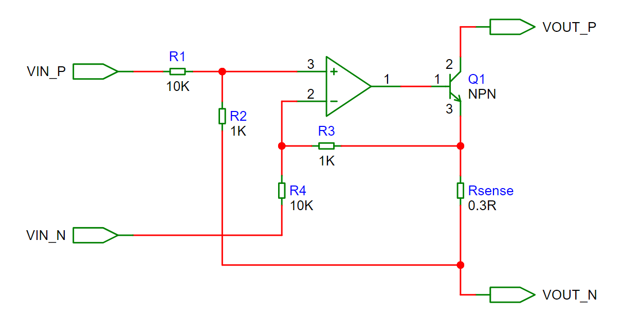
In this circuit, the conditions are: VIN_N = VOUT_N = 0V, VIN_P = 0~3V, Rsense current 0~1A, op-amp uses a 5MHz bandwidth,
VIN_P, after being divided by R1 and R2, enters the positive terminal of the op-amp, Vp, which is 0~0.2727V.
The voltage at the negative terminal of the op-amp, Vn, under the influence of the reduced open-loop gain (28.6dB), = VRsense * ((1 / Ao) + (R4 / (R3 + R4)) = 0.2943V.
At this time, the voltage difference between Vp and Vn is 0.2727V - 0.2943V = -21.6mV
From a time-based analysis perspective, when the actual current reaches 1A, the voltage at the negative input terminal of the op-amp is actually equal to the voltage at the positive input terminal. At this point, the op-amp should stop
. However, due to the error caused by the open-loop gain, we need to compensate for this voltage difference at the input terminal to stop the op-amp from continuing to oscillate.
The following diagram is a simplified diagram of the actual circuit, illustrating the main loops of the power stage output and feedback compensation.

To add this compensation voltage to the negative terminal of the op-amp, R5, R6, and C1 are added to the feedback loop.
R5 and C1 form an RC charging function, providing a voltage that builds up over a certain period of time to compensate for the negative terminal voltage during changes.
The main function of R6 is to isolate R3 and R4. The impedance of the voltage divider better regulates the influence of the RC charging circuit on the negative terminal voltage.
From a frequency domain perspective, this means adjusting the number and location of zeros and poles.
One often overlooked aspect in the op-amp compensation circuit diagram above is the voltage swing at the op-amp's output. This is a crucial signal source for compensation.
If the op-amp output does not show a voltage change during load current variations, the compensation circuit will be useless
unless the signal source is connected to a relevant location with voltage swing, or a transimpedance amplifier is used.
As shown in the diagram, with an output current of 1A, the op-amp output voltage is approximately VRsense + VQ2be + VR8 + VQ1be + VR7 = 1.82V.
When the output current is close to 0A (the transistor remains slightly on), the op-amp output voltage is approximately 1.4V (the actual Vbe voltage will be lower, around 0.6V).
When the step current is 1A, the op-amp voltage swing is approximately 0.4V, providing a maximum compensation voltage difference of approximately 0.4V to the op-amp's negative terminal. 0.2727 = 0.127V.
At this point, it can be observed that if the error voltage caused by the open-loop gain is greater than the voltage difference that the compensation circuit can provide, adjusting the compensation loop will reduce the speed.
It is necessary to increase the ratio of the compensation source voltage swing to the signal or select an operational amplifier with a higher bandwidth.

The feedback compensation circuit can be viewed as a resistor voltage divider structure. Capacitor C1 is analyzed using the time-domain method of RC charging.
To reduce the output stress of the op-amp, the resistance values R5 and R6 of the RC circuit are chosen to be on the order of kΩ, with a time constant below 1µs, and the capacitance is in the pF range.
Since the current settling time of the power stage is 200ns, we need to provide approximately 21mV of compensation voltage to the negative terminal of the op-amp at 200ns.
The total compensation voltage difference is 127mV. Initially, with R5 = R6, the capacitor needs to charge to 85mV at 200ns, which is 67%.
The capacitor value C1 is chosen to be a minimum value of 20pF, which generally negligible due to parasitic capacitance. Therefore, R is approximately 9kΩ.
Different ratios of R5 and R6 result in different response characteristics:
R5 limits the proportion of capacitor compensation; a larger capacitive ratio leads to greater low-frequency errors (DC components are also compensated).
R6 provides the remaining R portion of the required RC constant and also compensates for the voltage absorbed by R5 and C1 to ensure sufficient compensation components enter the negative terminal of the op-amp.
Of course, calculations can only guide the actual circuit; various parasitic parameters and actual device parameters will have an impact, requiring fine-tuning.
However, the RC compensation circuit considers charging and discharging, so the final response time needs to be increased by 200 ns.
The result is that the upper limit of the entire loop speed is approximately half the open-loop speed of the power stage;
the faster the op-amp, the less compensation is needed, and the smaller the error.
This step-based analysis method doesn't directly correspond to reality, as real-world changes are continuous rather than step-based,
and op-amps don't remain stationary. However, it does provide an analytical approach.
For time-domain debugging:
Without adding a compensation loop, input a step square wave signal and observe the output waveform. If the waveform edges are slow, the op-amp speed is insufficient.
If the waveform rising edge is fast enough and overshoot occurs, the op-amp speed is sufficient, and a compensation loop needs to be added.
If adding only a capacitor can reduce the overshoot without significantly decreasing the rising speed, then no resistor needs to be added.
If adding only a capacitor reduces the overshoot but the rising speed is too slow, add a resistor to increase the speed. Repeat this process to test the trend.
A simple summary of op-amp selection and matching is:
First, determine the maximum open-loop output speed by controlling the step input to the power stage. The final maximum speed of the entire loop should be approximately half of the open-loop speed.
Compare this to the design target to see if the speed requirement is met, and calculate the frequency corresponding to the slew rate at this point.
Select several op-amps that meet the actual situation (procurement, inventory, etc.), calculate the error caused by the op-amp's open-loop gain, and
observe whether the error meets the slew rate requirement. Finally, calculate the required value for the compensation loop based on this error.
Actual test results:

The current rise time is completed within approximately 500ns with no significant overshoot. The fall time is relatively long, which is due to the transistor tailing and the large base resistance.
A question might arise: since the current control is a DC output, why is this current response speed important?
This is because signal fluctuations can be converted into changes in a specific segment of the loop. For example, the fluctuation in the setting can be transferred to the fluctuation in the input voltage.
That is, if the input voltage fluctuates, the current can still remain constant according to this response speed, thus functioning as a constant current source as possible.
The following is a brief description of each circuit part:
Engineering Guidelines:

Power Input Section:

The USB power input is connected to USB_VINP, passing through two PMOS transistors in parallel as a load switching switch. Other models can be used, even a single transistor.
The maximum current is 4A. Since the package is SOT-23, the dissipation should ideally not exceed 0.3W.
The internal resistance of the 3401 transistor is approximately 60~80mΩ @Vgs4.5V, and it's a readily available and inexpensive model; connecting two in parallel is not unreasonable.
Q8 is used to control the switching of the USB load input. SW_P is connected to the toggle switch and is active high (approximately 1.4V).
The load is input from terminal P6, passing through D2 to the load transistor.
D1 and D2 provide reverse connection and reverse current protection. The maximum input current is 4A and the voltage is 50V. The diode used is an SS56 type.
Testing showed that using two diodes of the same type in parallel only reduced the voltage drop by 10%, so a single diode is used.
Moreover, according to the characteristics of Schottky diodes, the voltage drop is lower at higher temperatures, so a single diode is more cost-effective as long as the temperature does not overheat. Let the Schottky diode burn! ~~( ⓛ ω ⓛ *);
(Reverse leakage will also increase, but there is no sudden reverse current under normal conduction conditions, so it does not affect the operation).
Auxiliary power input section:
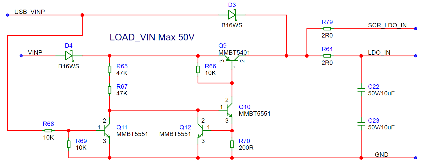
The USB input is connected to the linear regulator input through D3, which is used to prioritize the use of USB power as auxiliary power.
The load input is connected to the linear regulator input via D4 and Q9. Q9 controls the stopping of auxiliary power supply from the load when USB is connected.
Q11 shuts down the output of Q9 when the USB input voltage is greater than 1.4V.
R65 and R67 are connected in series to increase their voltage rating because they need to withstand 50V (it is recommended that the voltage across a 0603 ordinary resistor not exceed 50V).
Q10, Q12, and R70 form a constant current source to provide a relatively stable drive current to Q9 within the 4.5~50V input range. Using resistors to adapt to this voltage range results in higher power consumption.
Although Q9 only handles a maximum current of approximately 40mA, theoretically, Ibe only needs to meet 0.4mA or even less (β greater than 100) to be sufficient.
However, the saturation Vbe of the transistor varies according to the actual β. To obtain a lower Vce, β usually needs to be reduced to below 10.
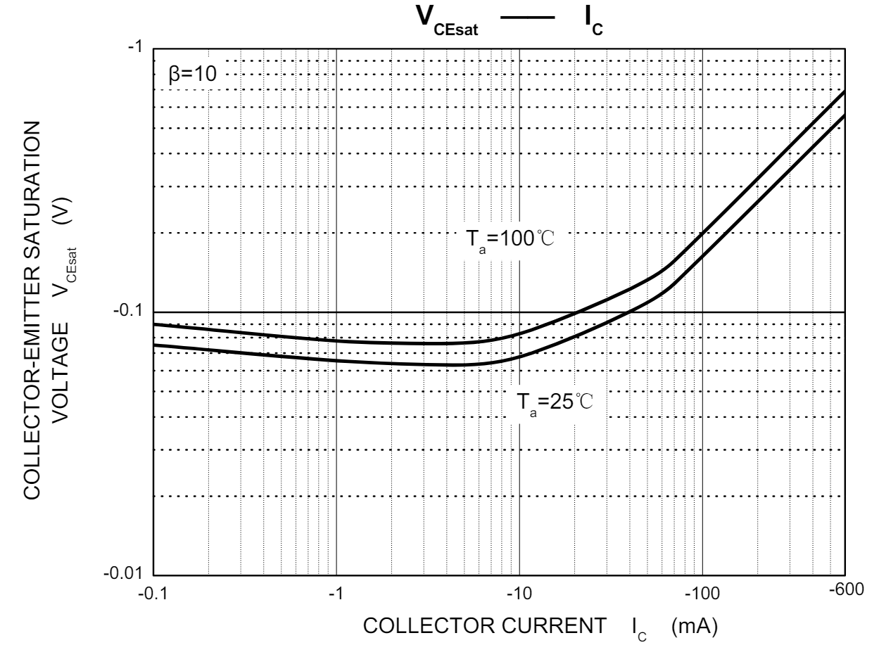
The Vce and Ic of the Changdian MMBT5401... The relationship table
shows that a constant current source is used to drive the base of Q9, providing approximately 2.7mA. Although β is around 15, the measured Vce is already around 0.1V.
A larger drive current would lead to excessive power consumption at high voltage input and would not contribute much to reducing the Vce voltage drop.
The USB input acts as an auxiliary power supply to the linear regulator input, with a maximum voltage drop of approximately 0.4V in the middle and a maximum power loss of approximately 0.5V at the load input.
The linear regulator output is 3.3V. Due to the circuit structure, the input-output voltage difference needs to be greater than 0.6V.
Including the losses of the switching circuit, this just meets the minimum input voltage of 4.5V.
Here, you might wonder why a PMOS is not used for Q9 if voltage drop is considered.
The reason is that using a MOSFET here would require clamping the gate-source junction of the MOSFET, and the price of a high-voltage MOSFET is much higher than that of a transistor.
Transistors have inherent high voltage withstand and stable clamping characteristics, making them very useful in many scenarios. Transistors are awesome!
Because the input capacitor of the linear regulator is a ceramic capacitor, which has ultra-low ESR, it is prone to resonant boosting with the inductance of the wires during hot-swapping.
Therefore, the function of R79 and R64 is to increase the link damping, suppress the resonant point, and avoid excessively high voltage spikes during hot-swapping.
C22 and C23 are connected in series to improve the withstand voltage, because ceramic capacitors exceeding 50V are expensive and used in small quantities.
It's important to note that the OLED screen's power supply current will continuously exhibit a triangular wave of about 10kHz, presumably from the charge pump
current. Due to the small energy storage capacitor in the circuit, the total power input will generate increased voltage ripple, causing the ceramic capacitors to whistle.
Aluminum electrolytic capacitors were not used due to the high temperature considerations, and tantalum capacitors have insufficient withstand voltage and are extremely expensive.
This phenomenon is normal and is more pronounced when the auxiliary power supply voltage is high.
Therefore, please do not overlook the impact of the OLED screen's operating current on other components.
Auxiliary power supply voltage regulation section:
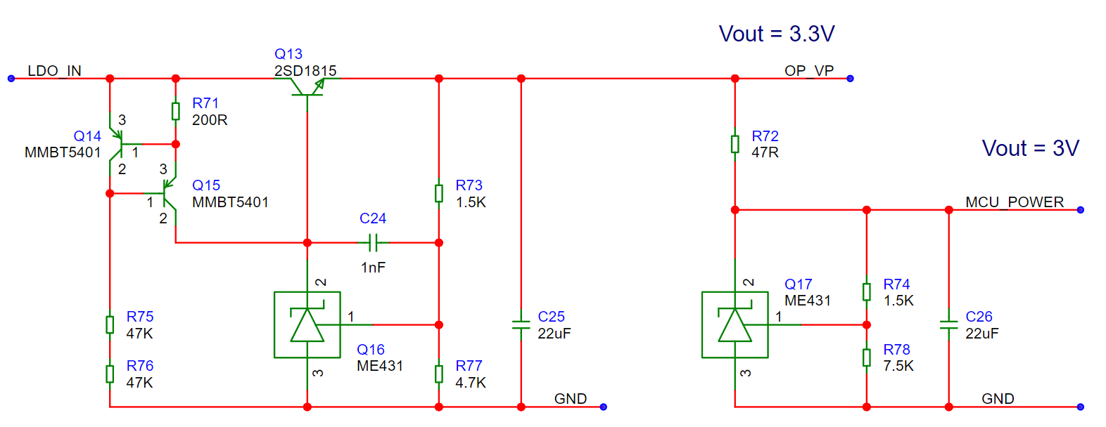
The design uses a linear regulator built with discrete components, as integrated solutions generally do not exceed 40V.
Q14, Q15, R71, R75, and R76 form a constant current source to power the base of the 431 and Q13, providing approximately 2.7mA (the 431 requires a supply of more than 1mA).
Due to the transistor current amplification method, C24 is used to reduce the 431's output response speed; I would call it a self-deception capacitor, stabilizing the loop.
The first-stage 3.3V regulator primarily powers the op-amp, giving it more output voltage margin, and also provides power to the MCU section.
The second-stage 3.0V regulator primarily powers the MCU, and also provides a reference voltage for the ADC acquisition and DAC output.
Note: The 431 chip can be replaced with chips from various manufacturers, as long as the pinout is the same; the voltage divider resistors can be adjusted by changing the reference voltage.
Current sampling and setting section:
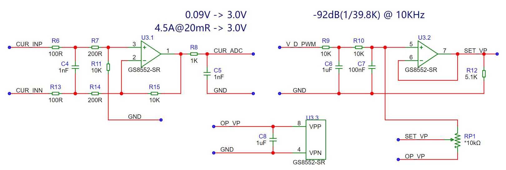
The left side is the load current sampling circuit, and the right side is the load current setting circuit.
Current sampling uses low-side sampling (because the external interface has only one negative circuit, so there is no current branching issue).
The resistance value of the current sampling resistor should be as large as possible while meeting power consumption and voltage drop requirements, because resistor-to-current gain is cheap and stable.
Here, the maximum sampling current is designed to be 4A, and a 20mΩ resistor generates a voltage difference of 80mV and a power consumption of 320mW, which meets the requirements.
To reduce the influence of copper foil temperature drift and voltage sampling, differential mode is used for current sampling (single-ended mode is used for voltage sampling).
The current-to-voltage coefficient is 4.5A->3.0V. R8 and C5 are used to provide and absorb charge for the ADC sampling capacitor (not for filtering).
The current-setting DAC uses PWM filtering, which is simple and has excellent linearity.
However, the disadvantage is also obvious: it cannot simultaneously obtain smooth output and rapid changes, so it is generally suitable for DC scenarios.
V_D_PWM is connected to the microcontroller's PWM output pin. Since the power supply is provided by the 431 with a stable reference voltage, the amplitude of the square wave is also considered stable.
The values of the filter components R9, C6, R10, and C7 are chosen based on specific criteria. Since the microcontroller's DAC is 10-bit and the frequency is approximately 10kHz,
the output DAC voltage jitter should be less than 1/11 bit, or 1/2048. Lower values are possible, but slower.
Therefore, the filter circuit needs to attenuate the input fundamental frequency component to below 1/2048, or -66dB, to meet the requirements.
The attenuation dB of multiple filter stages is additive, and two-stage filtering better balances attenuation factor and rate of change (a steeper frequency response inflection point).
In the actual design, considering the available materials, a combination of 10KΩ, 1uF, and 100nF is used, achieving an attenuation of -92dB at 10kHz. Since DC is the primary current source, it doesn't matter how slow it is.
Potentiometer RP1 is used to switch the output to square wave current mode. In square wave mode, U3, C6, C7, and R12 are not soldered, and resistors R9 and R10 are changed to 0Ω.
At this time, the microcontroller will not be able to read the output current. The load current is approximately a 10kHz square wave, the amplitude of which is adjusted by potentiometer RP1, and the programmable current changes the duty cycle.
The op-amp used here is the 8552, a self-zeroing rail-to-rail op-amp. The self-zeroing function eliminates the need for offset voltage compensation,
and this model is widely used (reportedly due to its high usage in e-cigarettes) and relatively inexpensive.
Note: Other models or manufacturers of op-amps can also be used here. There are no bandwidth requirements, but the offset voltage needs to be as low as possible below 0.1mV (current sampling).
Voltage acquisition section:
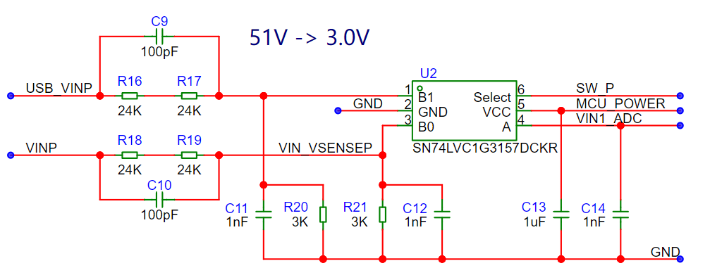
Here comes the most redundant part.
Voltage acquisition uses a single-ended resistor divider. The MCU's 0V reference is connected to the 0V input terminal.
Since it is necessary to switch between acquiring the USB and load input voltages, but the MCU doesn't have many extra pins, yes, this is the torture I created for myself,
so I added an analog switch to switch the acquisition voltage. Moreover, the voltage division ratio of the load input and USB input must be consistent.
The switching between the load input and USB input is controlled by an external switch, and the MCU is unaware of it throughout the process. What is acquired is the voltage applied to the power transistor.
C14 is an energy storage capacitor near the ADC pin, used to provide charge to the ADC's sampling capacitor.
Then you will find that there are two small capacitors, C9 and C10, connected in parallel with the resistors on the voltage divider. What is this for?
That's right, it's for the oscilloscope function!
Because we cannot reduce the capacitance on the secondary side and ADC side for sampling reliability, and the upper resistor has a relatively large value,
this creates a low-pass filter with a low cutoff frequency. Furthermore, the voltage division ratio changes with frequency.
Since the secondary side cannot be reduced, we add an AC path to the primary side, allowing the AC component to bypass the resistor and enter the secondary side.
What should this capacitor ratio be?
It should be the same as the voltage division ratio of the resistor, and note that this includes all parasitic capacitances in the circuit.
The fine-tuning capacitor on the oscilloscope probes is this upper capacitor. After adjusting the ratio, a stable attenuation ratio can be obtained across the entire frequency band.

This design does not require precise ratios because the oscilloscope does not require high precision,
but it is important to use NP0 or C0G capacitors for both the 100pF and 1nF capacitors to reduce temperature drift and errors.
Temperature protection section:
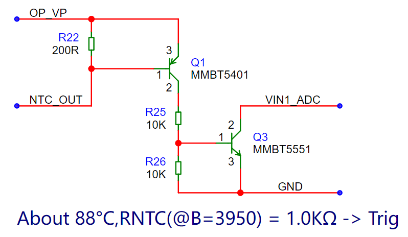
The NTC for temperature protection is placed on the power transistor board. Temperature changes cause changes in resistance. (Note: Do not solder the NTC on the power board as a fixed resistor! (╯▔皿▔)╯)
The transistor has a useful built-in reference voltage Vbe. Here, we use Q1's Vbe to compare whether the NTC resistance has dropped to a certain value.
Q3 is used to increase the gain, making the trigger point for protection steeper. The output pulls down the voltage entering the ADC.
When the microcontroller detects that the measured ADC value is too low, it will trigger undervoltage protection, thus achieving overheat protection.
Adjusting the value of R22 here will change the trigger value for temperature protection.
Due to the thermal resistance between the thermistor and the power transistor, and the inconsistency of multiple transistors connected in parallel, it is recommended that the temperature protection value be set relatively conservatively.
Button circuit:

An analog voltage divider method is used to read the buttons. This method has moderate reliability, but it is generally not a problem as long as it is not exposed to moisture.
These resistance values are obtained by solving equations, and the voltage divider ratio is relatively evenly distributed, allowing for relatively reliable identification of single button presses and multiple simultaneous presses.
Power stage output circuit:
The power stage output uses a Darlington configuration to reduce the load on the op-amp output and auxiliary power supply, and also increases the current amplification factor.
Q1 and Q6 are used here to allow the current to drop quickly when cutoff is needed, discharging the Ib of the power transistor.
C1, D1, D2, and R11 provide bias for the two driver transistors. C1 provides the AC drive voltage for Q6, ensuring that the base of Q6 can be below 0V when it needs to conduct.
The minimum voltage drop under full load for the power stage is: VR16 + VR12 + VQ3be + VR2 + VR1 + VQ1ce = 1.4V.
However, due to the presence of reverse polarity protection diodes and a total current sensing resistor in the preceding stage, approximately 0.8V needs to be added. Additionally, there are internal resistances in the wire sockets, so the minimum input voltage is at least 2.3V.
R1, R6, and R12~R15 are defaulted to 0Ω, but their values can be changed to adjust the response.
Power transistors Q2~Q5 can be replaced according to the actual situation, or the performance of different transistors can be tested.
The base resistor of the power transistor is used to balance the Vbe caused by inconsistencies in the transistors. A larger base resistor provides better balancing, but it reduces speed.
For example, at a total current output of 1A, if the maximum Vbe error between the four transistors is 20mV, then a 0.4mA current difference will be formed across the 47Ω resistor,
accounting for 16% of the total 2.5mA base current. Assuming the transistors have similar beta values, the average power error will also be around 20%.
Of course, a balancing resistor can be added to the emitter of the transistor, but the circuit characteristics will be different.
Since four power transistors are used, the schematic uses a multiplexed block function, but due to inconsistent PCB layouts, the PCB is not reused.
Op-amp output control section:

The op-amp compensation parameters here are applicable to models with a bandwidth of 5MHz~10MHz, but the specific parameters need to be fine-tuned according to the actual situation. Actual
measurements show that op-amps with bandwidths of 3MHz and below cannot achieve a current rise time within 500ns; it is recommended to use op-amps with bandwidths of 5MHz or higher.
(Actual tests show that COS722, SGM722, etc., can achieve good results.)
Note that the offset voltage of the op-amp will affect the minimum output current and the consistency of multiplexing, and will also affect the accuracy of the set current.

This circuit is used to reliably shut down the op-amp output when the output stops.
Because the offset voltage of the op-amp will still have current output when the set voltage is 0V,
R23 is used here to pull up the op-amp when the PWM stops, making the negative terminal voltage of the op-amp input set higher than the positive terminal, thereby reliably stopping the output current.
V_D_PWM is connected to the PWM output pin. Q2 acts as a diode and increases input impedance. C15 keeps Q4 conducting, and R27 discharges when stopped.
Q5 is used to light the indicator light for load current activation.
Q4 needs to be a model with the lowest possible internal resistance to reduce voltage drop during normal operation. Q5 uses a MOSFET because its gate requires high input impedance.
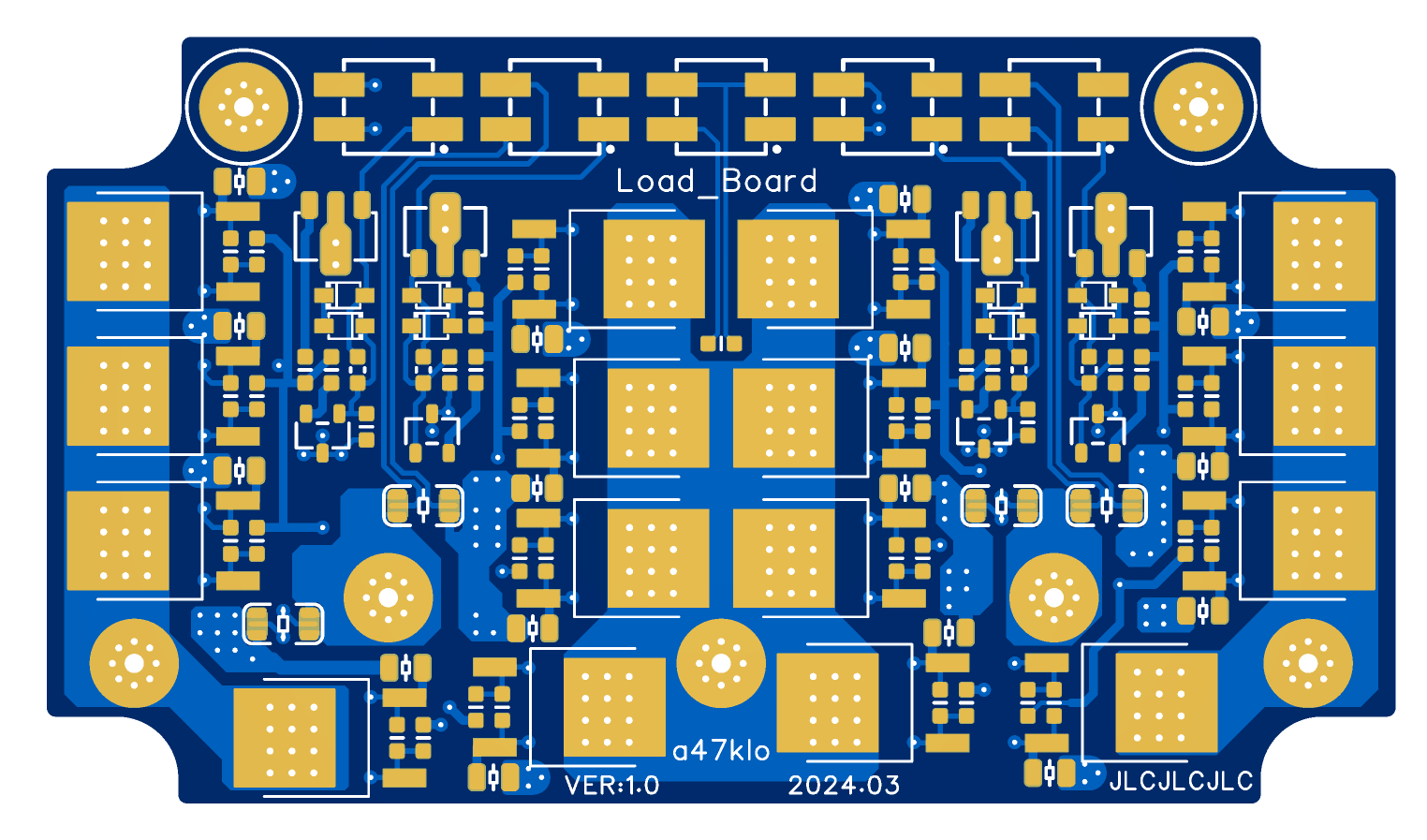
PCB Description:
This design consists of three PCBs: a main control board, a power board, and a display board. The
main control board is mounted on the upper layer, the power board is mounted below the main control board, and the display board is mounted in front of the main control board.
Due to space constraints, component numbers are not marked on the PCBs, but there is a separate component value layer for easy component mounting.
When ordering, you can select the customer code and add it to a specified position, so that the customer code will be placed in an inconspicuous position after installation.
All components are front-mounted, except for the screen, which is soldered on the back.
It is recommended to use SMT assembly or a preheating station for soldering. Avoid using a soldering iron to solder the screw posts and transistors on the power board.
Main Control Board:
Note: The PCB should be 1.6mm thick. Avoid adding extra solder to the solder mask openings on the back and the screw holes on the front to prevent affecting screw alignment.
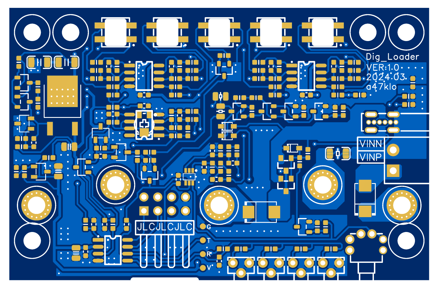
Power Board:
Note: The PCB should be 1.0mm thick. Avoid adding extra solder to the solder mask openings on the back to prevent affecting assembly alignment.
The flying leads on the PCB are indicators between several power supply nuts, ultimately connected by the main control board; ignore them on the base board.
Display Board (TOP layer is the mounting back):
Note: The PCB should be 1.0mm thick.

Component assembly layers are drawn on all PCBs:
you can export this layer as a separate PDF or solder components according to the highlighted areas on this layer.

The PDFs starting with ASM in the attachment are the exported PDFs of the assembly layers.
Assembly Description:
Component values in the BOM are based on component names. Components with an asterisk (*) before their names are not mounted by default.
The attached BOM has corrected the names of buttons and sockets. For
large-capacity (4.7uF and above) ceramic capacitors in the design, except for those marked with 50V, all others can use models with a voltage rating of 10V or higher.
For small-signal transistors, any model with a withstand voltage of 50V or higher can be used for replacement.
Main control board:
It is recommended to use 8-10mm long tactile buttons for easier button press after assembly.
Since the MCU programming port shares the button sampling port, capacitor C3 (button filter capacitor) needs to be removed before programming and then soldered back on afterward.
The self-locking switch uses a 5.8*5.8mm horizontal package and requires a keycap of 5mm or larger for easy pressing.

Power board:
These pads on the power board are for soldering M3 nuts. Note that the specifications are slightly special; common outer diameters do not match.
The bottom row of nuts is for fixing and conduction, so the screws on the main control board must be tightened. The top two are only for limiting and can be left untightened.
It is important to ensure that the surface-mount nuts are firmly pressed into the PCB and kept flat during assembly; otherwise, connection problems and board deformation may occur.

Surface mount nut specifications:
Note that the widest diameter of the base is 4.5mm, while the pad is only 5mm. A diameter that is too wide will not accommodate
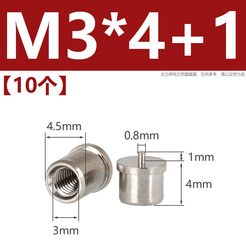
the display panel.
The LEDs of the display panel face the front after assembly, which is the bottom layer of the board. Flip-chip


 demo video on Bilibili.


 京公网安备 11010802033920号

 HYB39S256800T-10


