I. Design Purpose:
Personal design to meet personal daily use.
II. Functional Requirements:
(1) Maximum total power is 22.5W.
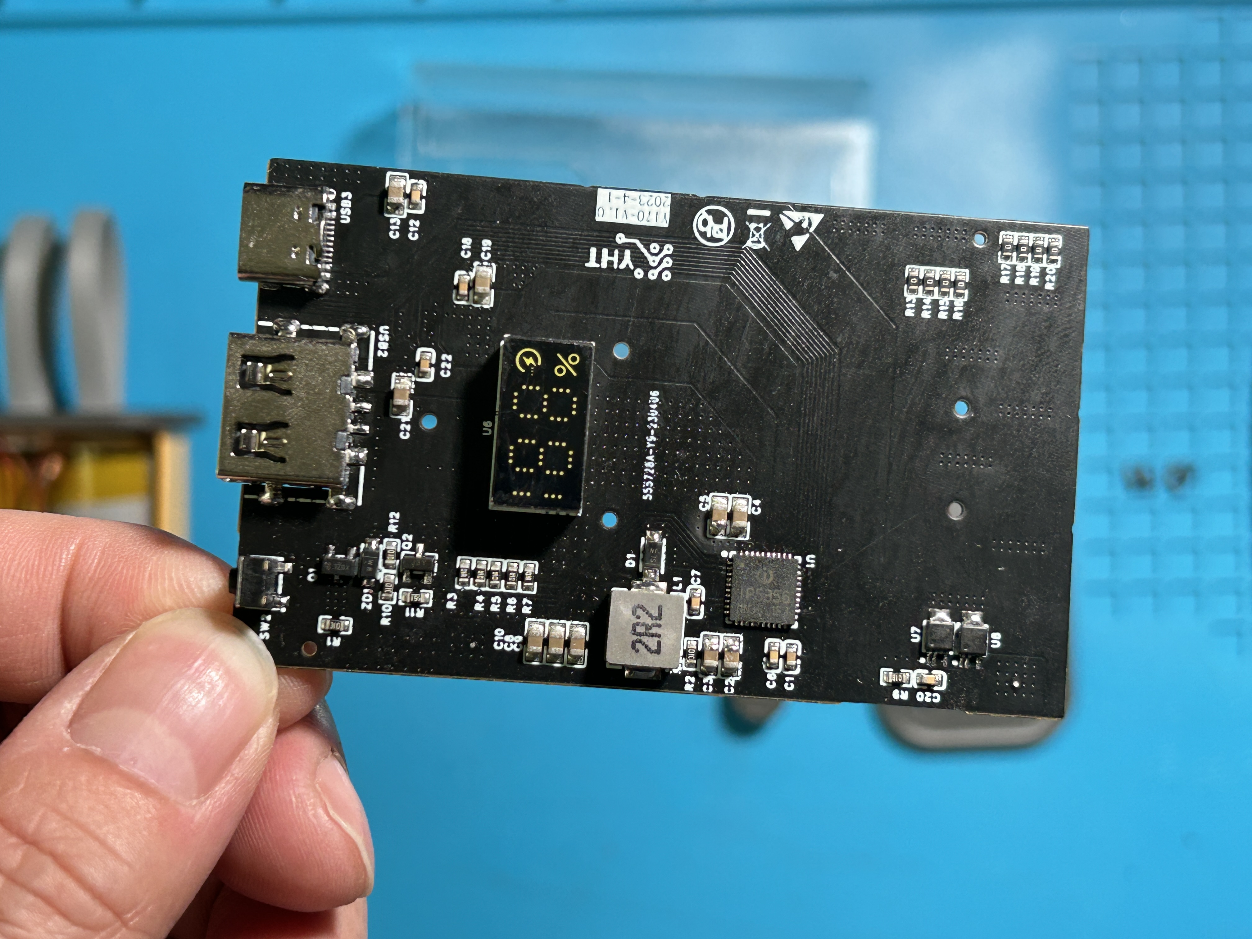
(2) It has one Type-C, one USB-A, one Apple Lightning, and one Type-C charging cable.
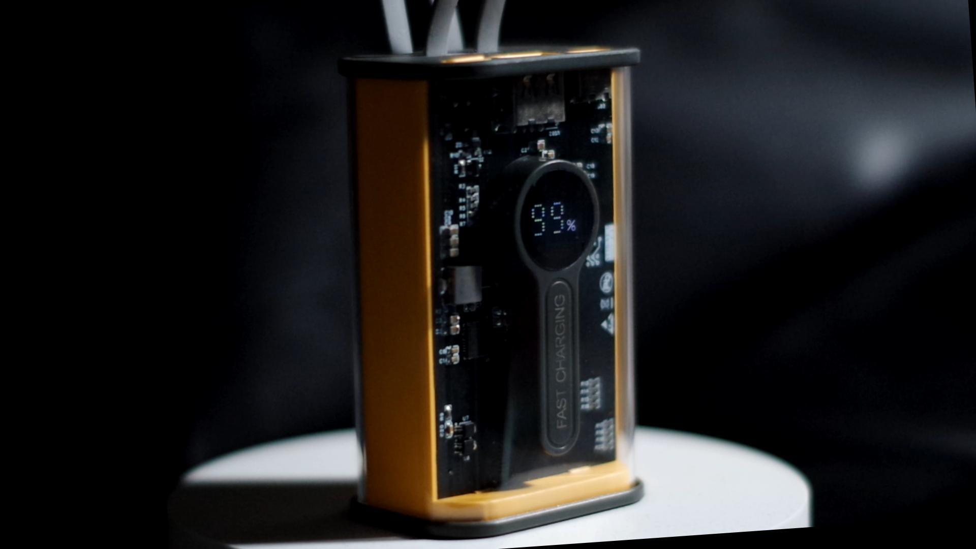
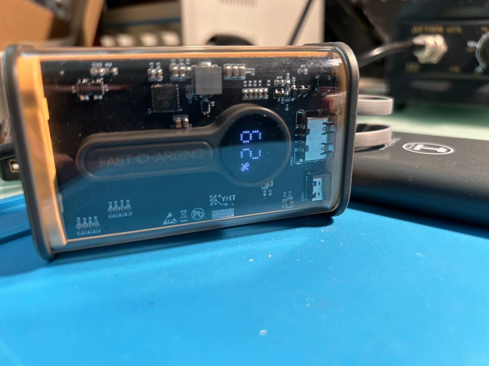
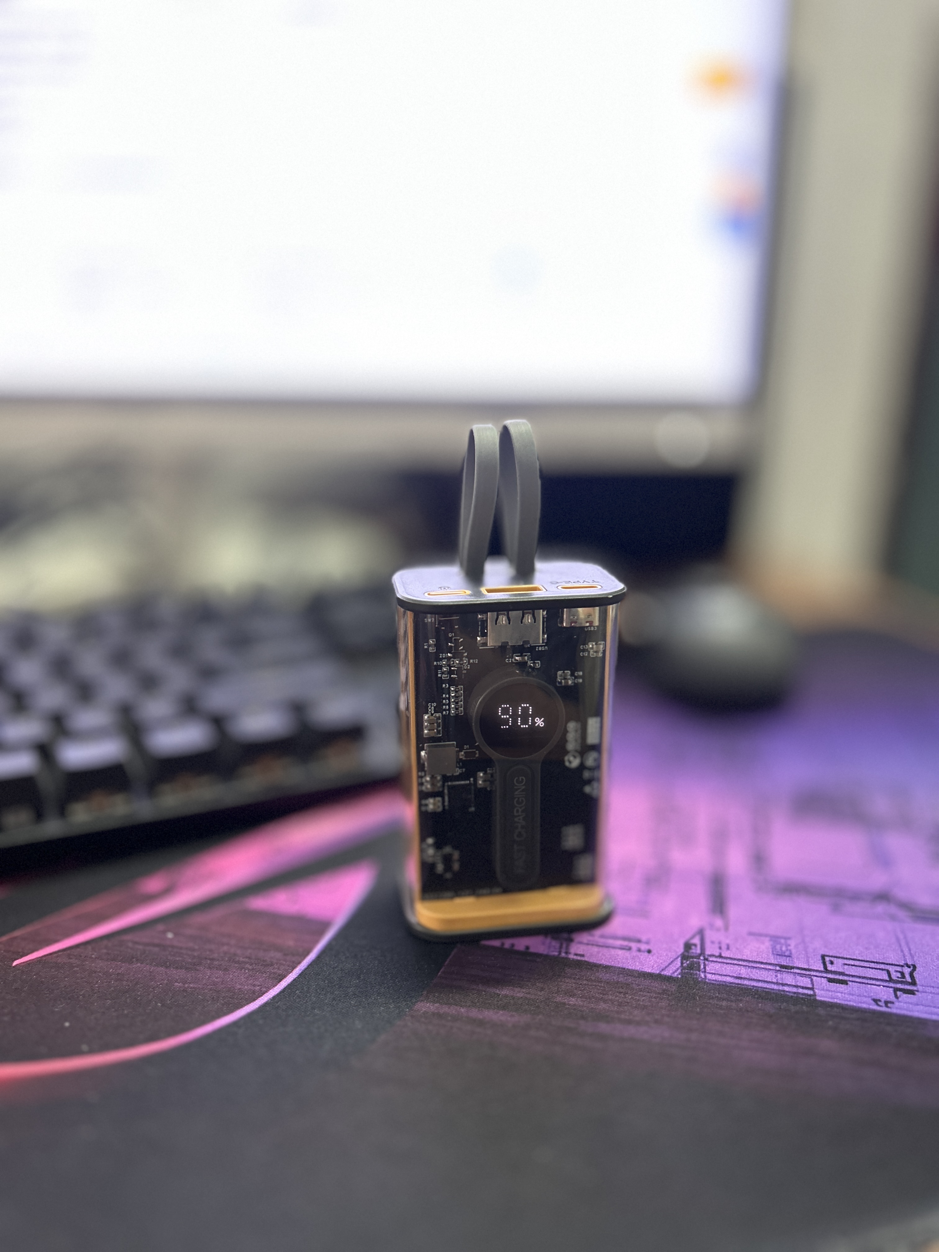
(3) Transparent shell.
(4) Battery capacity can be selected as needed.
(5) Digital tube displays battery level.
III. Design Summary:
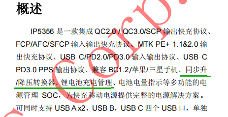
(1) The IP3556 solution is used for design.
(2) Ready-made shell material is used, and the motherboard frame is shaped according to the size and hole position of the shell material.
(3) Digital tube displays battery level and usage status.
IV. Problem Analysis:
(1) First, the voltage of a typical mobile phone battery is 3.7V, and the charging voltage needs to reach 4.2V to charge the battery.
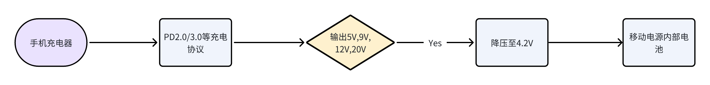
(2) The voltage output of a typical mobile phone charger is currently 5V, 9V, 12V, 20V, etc., so the phone will first perform voltage reduction processing before charging the battery.
(3) The nominal voltage of the 21700 battery inside the power bank is also 3.7V, and the charging voltage is 4.2V. Therefore, to charge the phone, it is necessary to boost the voltage (to 5V, 9V, 12V, 20V, etc. to achieve the same effect as the phone charger).
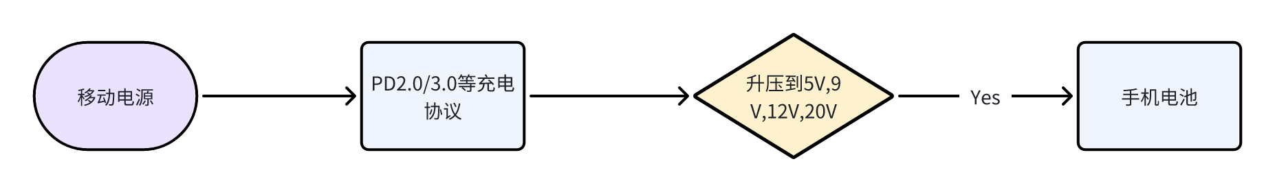
(4) How to notify the power bank to boost the voltage? The answer is that the IP5356 communicates with the charging management IC inside the phone, that is, PD2.0 and PD3.0. For now, we don't need to worry about the principles of PD2.0 and PD3.0. We only need to know that these two are the handshake protocols for charging.
(5) After clarifying the idea from the power bank to the phone, let's continue with the idea from the phone charger to the power bank. As mentioned earlier, the output of the phone charger is generally 5V, 9V, 12V, 20V. Therefore, to charge the battery inside the power bank, it is necessary to reduce the voltage to 4.2V. Otherwise, the high voltage will directly damage the battery.
(6) At this point, we can basically understand the general process of charging and discharging. That is to say, the main control IC inside the power bank must have the two basic functions of boosting and bucking. We can see from the IP5356 manual as shown in the figure below:
For a detailed explanation of the principle, please refer to this link:
https://bwhsczhz9kt.feishu.cn/docx/UUhwdlZatoMfy7xmwM1c197nnOh
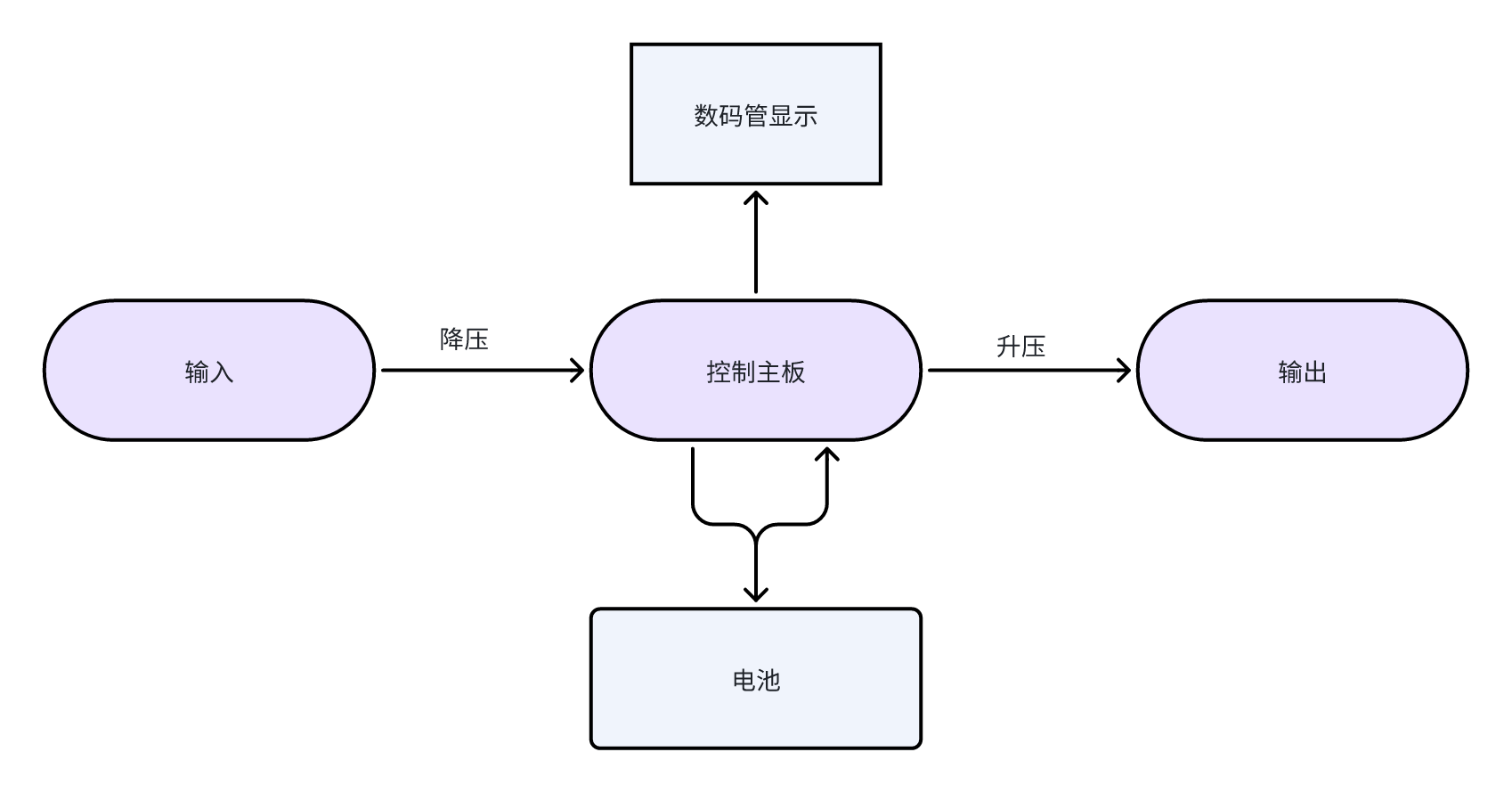
V. Overall Design Block Diagram
VI. Hardware Circuit Composition
(1) USBA Interface

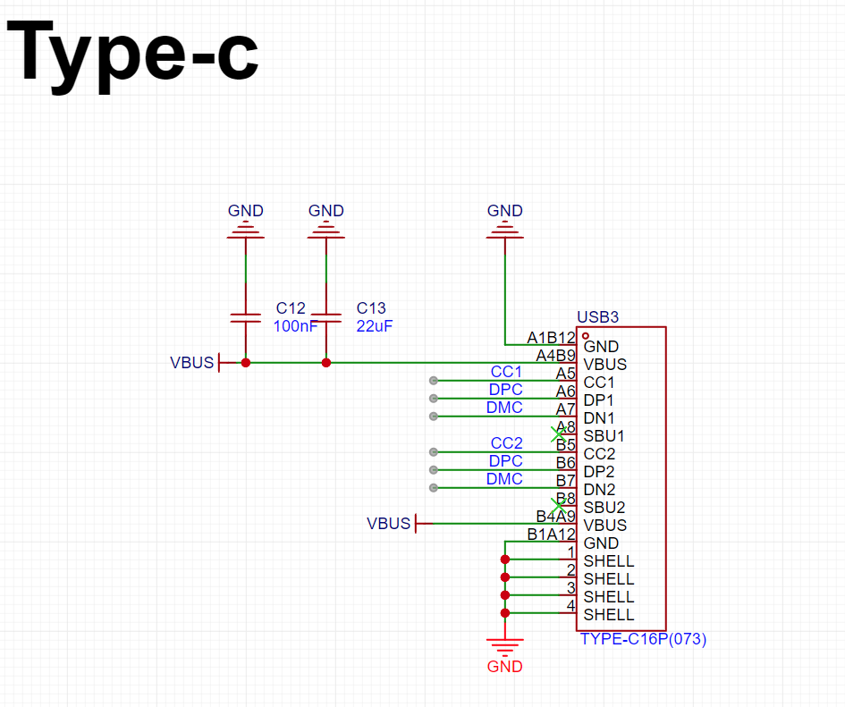
(2) Type-C Interface
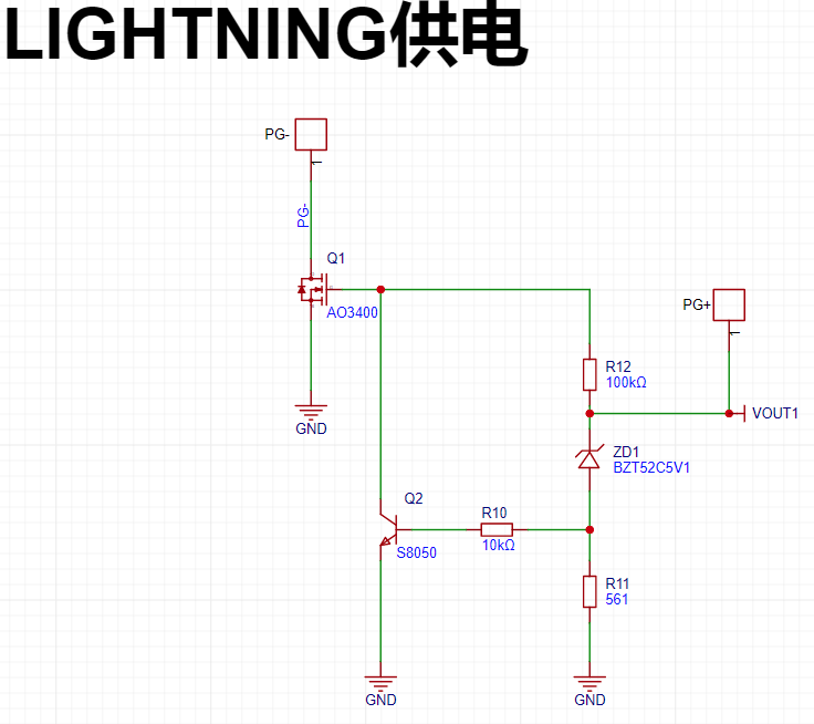
(3) Lightning Power Supply
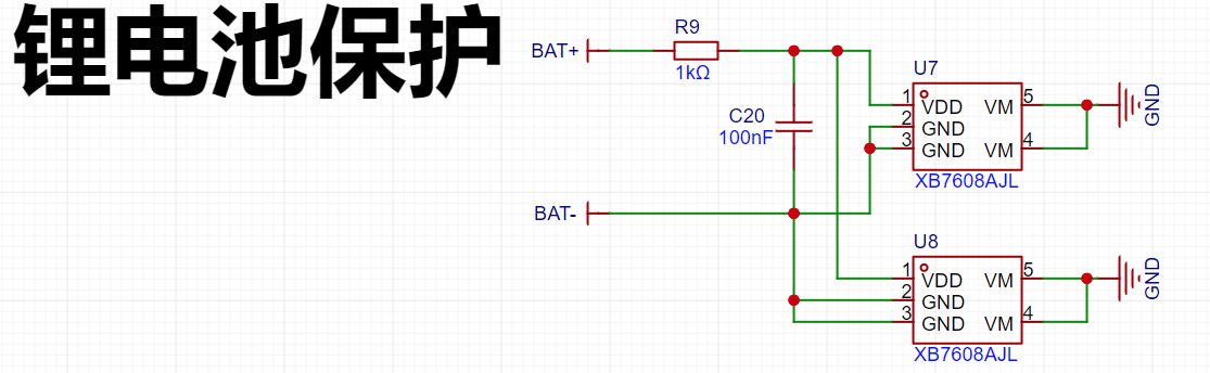
(4) Lithium Battery Protection
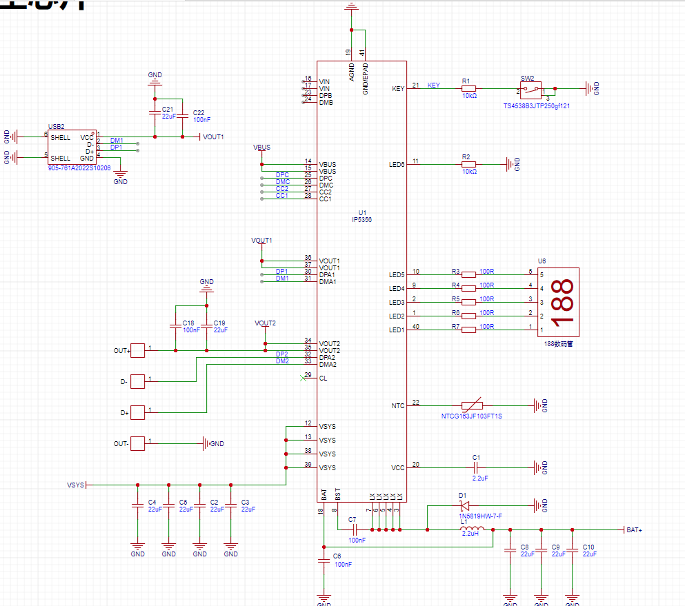
(5) Main Control Circuit
VII. Program Flowchart
No program required, pure hardware design
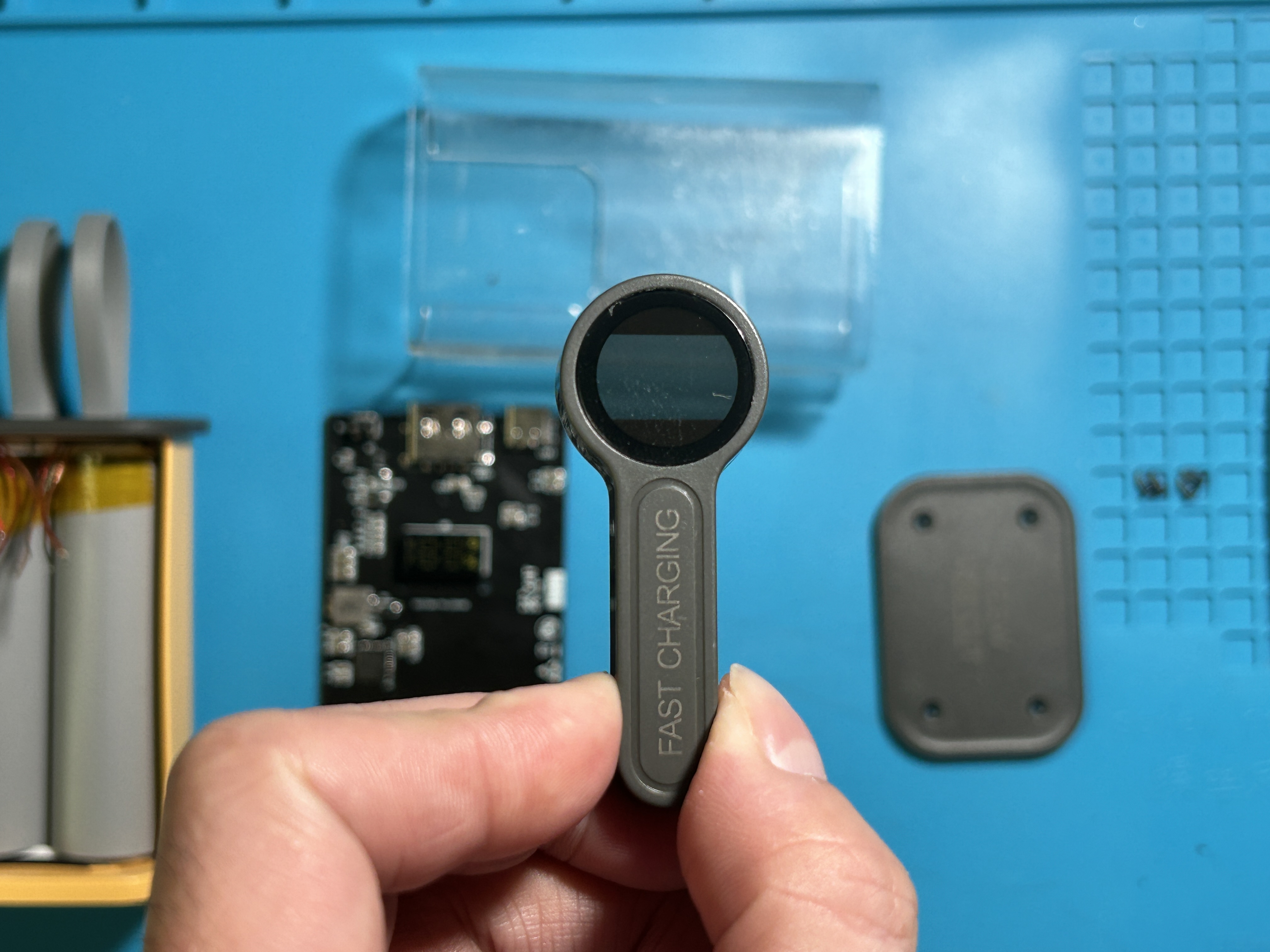
VIII. Physical Display


IX. Precautions
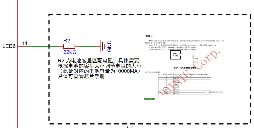
(1): The battery capacity can be selected according to personal needs, but it is necessary to replace the matching resistor on the motherboard as shown in the figure below:
(2): The battery model currently used is 21700, and the size is in line with the shell requirements. For other battery sizes, please pay attention to the battery voltage and size.
(3): The IP5356 model requires the digital tube-specific model: IP5356-188-BZ. Please be careful not to buy the wrong one. The relevant purchase link is in the BOM list.
(4): During the replication process, safety is the top priority. Do not short-circuit the positive and negative of the battery to avoid the battery catching fire. I will not be responsible for any accidents that occur.
(5): For more precautions during the production process, please go to Bilibili to watch: https://www.bilibili.com/video/BV1no4y1u7o9/?spm_id_from=333.999.0.0&vd_source=5f8281657f114a37116180800654c4ec
X. Using the power bank as the starting point for the project, learn and use AD software. The open source tutorial has been uploaded to Bilibili. There are a total of 15 lessons, including schematic drawing, PCB board drawing, PCB soldering, power bank assembly, etc.
https://www.bilibili.com/video/BV1no4y1u7o9/?spm_id_from=333.999.0.0&vd_source=5f8281657f114a37116180800654c4ec


 京公网安备 11010802033920号

 177-714-1-15GP6K5-24LCN


