I. Project Background
Because I'm quite sensitive to static electricity and induced current when soldering circuit boards, I've always wanted to make a battery-powered soldering iron. Recently, while working on other projects, I made a 1.9-inch touchscreen panel for an 88*38 box, so I used that opportunity to create one.
II. Hardware Components
The hardware mainly consists of a charging section, a main control section, and a battery.
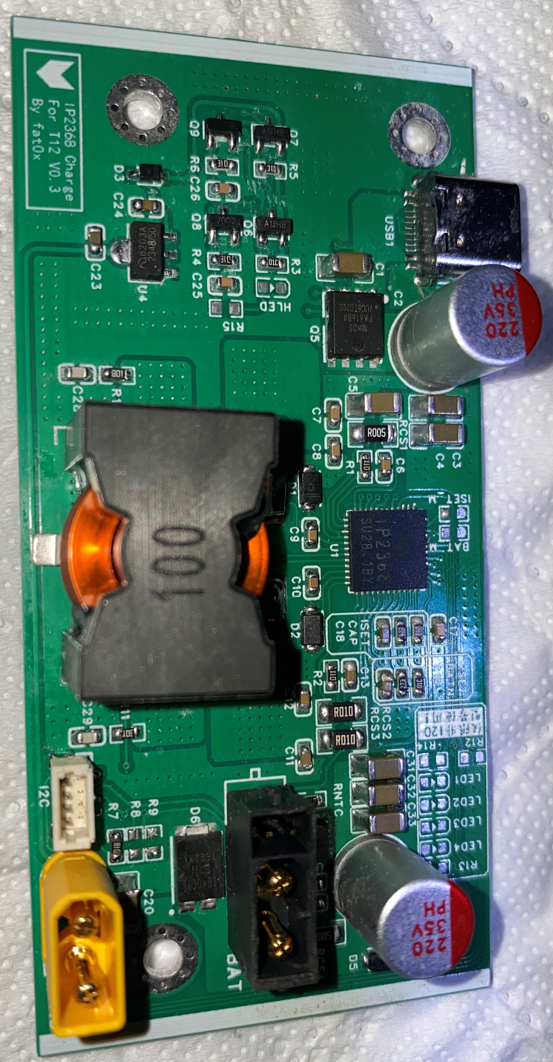
1. The charging section
uses an IP2368, allowing the soldering iron to be powered by a fast-charging adapter. For data monitoring, the IP2368-I2C-COUT model is used to monitor various charging parameters. Since the IP2368's TYPE-C output function is not used, an LTC2944 is added to implement battery level monitoring and other functions.
The IP2368 charging section references some open-source projects, mainly Xiaoyu's project, which can be found at: https://oshwhub.com/wzw666/ip2368
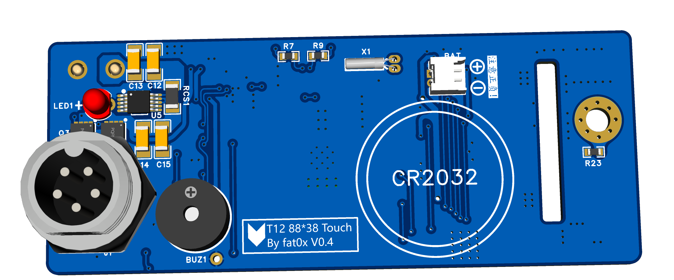
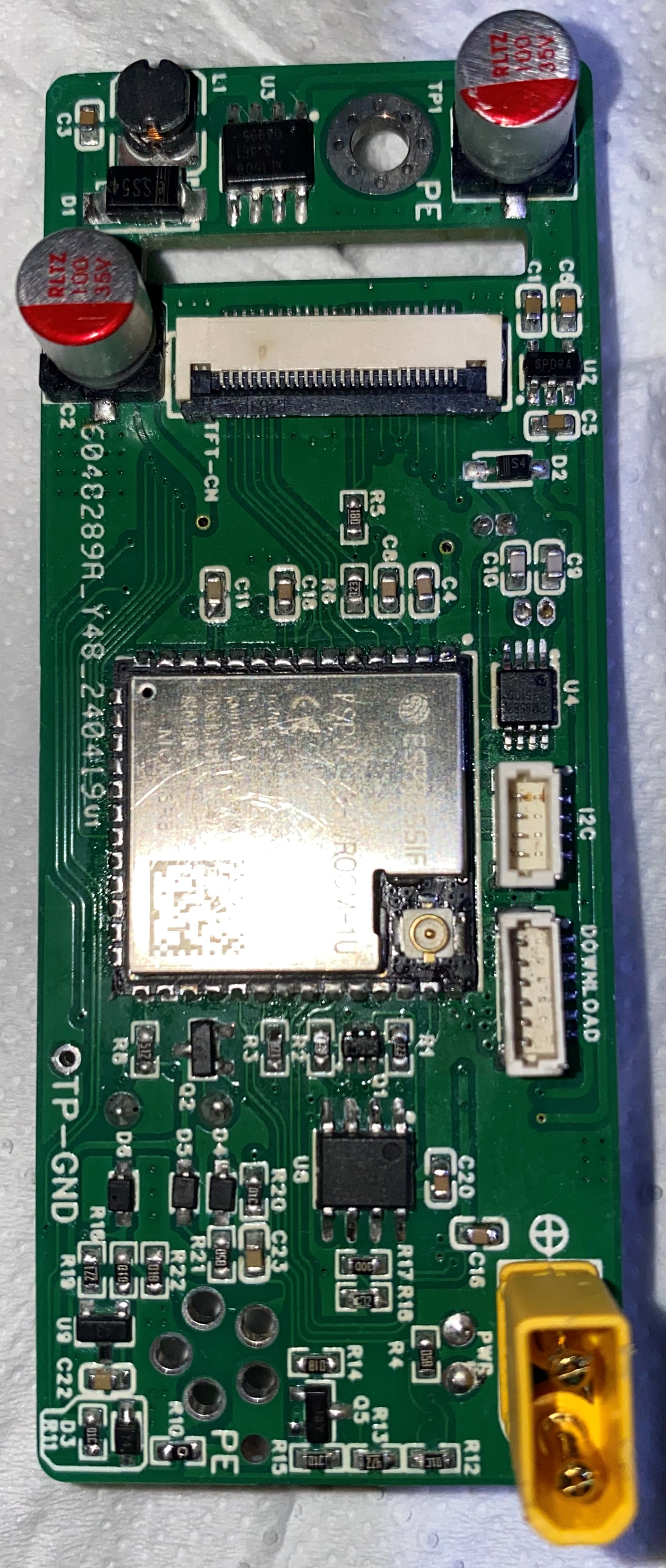
2. The main control section
uses an ESP32-S3 and a 1.9-inch capacitive touchscreen.
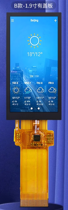
(1) 1.9-inch touchscreen
ST7789V2 main driver + CTS816D touch driver. The screen is good, but the size is a bit awkward, so the price is a bit expensive.
The reason for choosing it is that it can be installed on an 88*38 chassis panel.
(2) The main control chip ESP32-S3
is nothing special. The N16R8 version was chosen. A smaller capacity version can also be chosen to save costs. When using it, you should note that some pins cannot be used, such as the pins of USB HOST and the pins occupied by internal FLASH and RAM.

(3) The soldering iron tip
is based on ESP32PicoD4. Project address: https://oshwhub.com/xpya/open-t12-zhu-que-t12, but many modifications have been made, including the pin definitions of the soldering iron tip. It should be noted that the pin definitions of many T12 soldering station projects are different. Before inserting the soldering iron tip, carefully check whether the pins of the soldering iron tip and the pins of the main control board are consistent. Otherwise, it may not work at all, or even burn out the CPU!
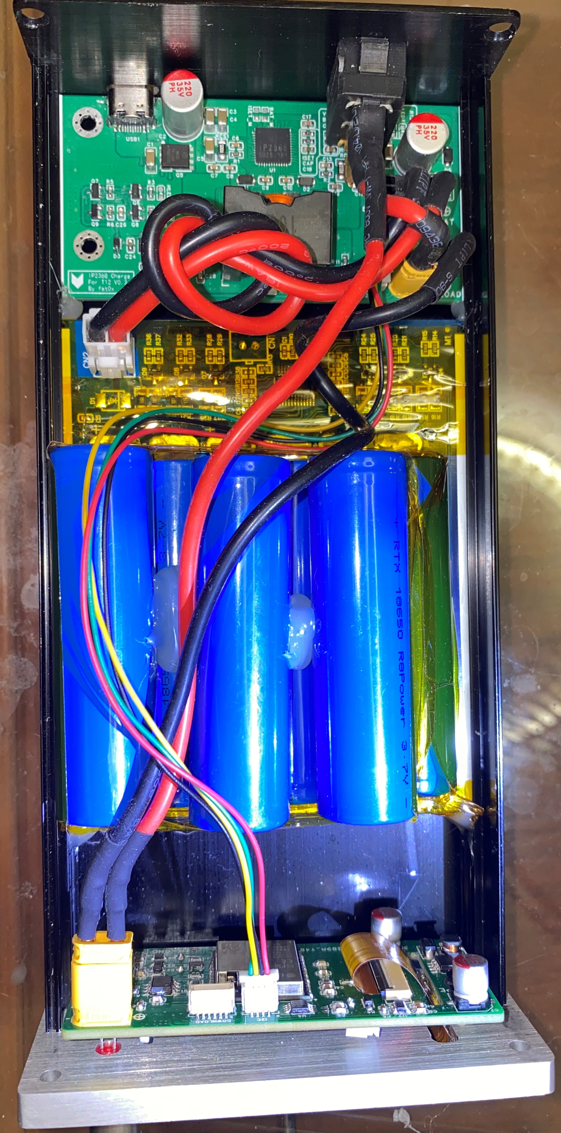
3. Battery:
The batteries were purchased as finished 6-cell lithium battery packs from Taobao, for an 88*38mm casing. (See attached image).
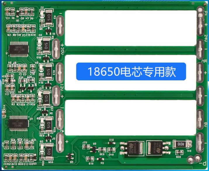
The main control board for this project can also be powered by a 24V switching power supply. However, an AC socket is required for the rear panel of the casing.
4. Panel:
Since there were no ready-made 88*38mm panels compatible with a 1.9-inch touchscreen, I had to build one myself using a small CNC machine.
The type of machine bed I used:

To be honest, it's not that this type of machine bed can't be used for machining aluminum alloy, but it's quite laborious.
Because some parts of this machine bed use bakelite, plastic, and 3D printing materials (black parts in the image), the rigidity is insufficient, and tool skipping is severe at high feed rates. Therefore, the feed rate F was set very low. With
a Z-axis depth of cut of 0.2, F10 was barely enough, and the efficiency was too low; it took an entire night to produce just one LCD slot. Mass production would require a professional factory; this is only suitable for making small prototypes.
Modeling was done using MasterCAM to generate G-code, followed by SolidWorks simulation. After confirming everything was working correctly, I used engraving software on the small CNC machine bed.

III. Software Section
The software utilizes the Arduino framework, with VSCODE + Pattern IO for development. The native Arduino IDE's compilation speed is incredibly slow, especially with large amounts of code; it takes more than a whole meal to finish compiling.
The UI uses LVGL8. Although LVGL9 has been released, a brief attempt at porting it revealed it wasn't as easy as LVGL8 and seemed to have bugs, so it was abandoned and will be implemented later.
Key software features include:
1. Integrated soldering tip temperature calibration: Allows users to calibrate the output voltage of the soldering tip thermocouple against the measured temperature at 15 voltage points via the touchscreen UI, ensuring highly accurate temperature readings. High-precision temperature measurement methods, such as using a FLUKE thermal imager, are recommended for calibration.
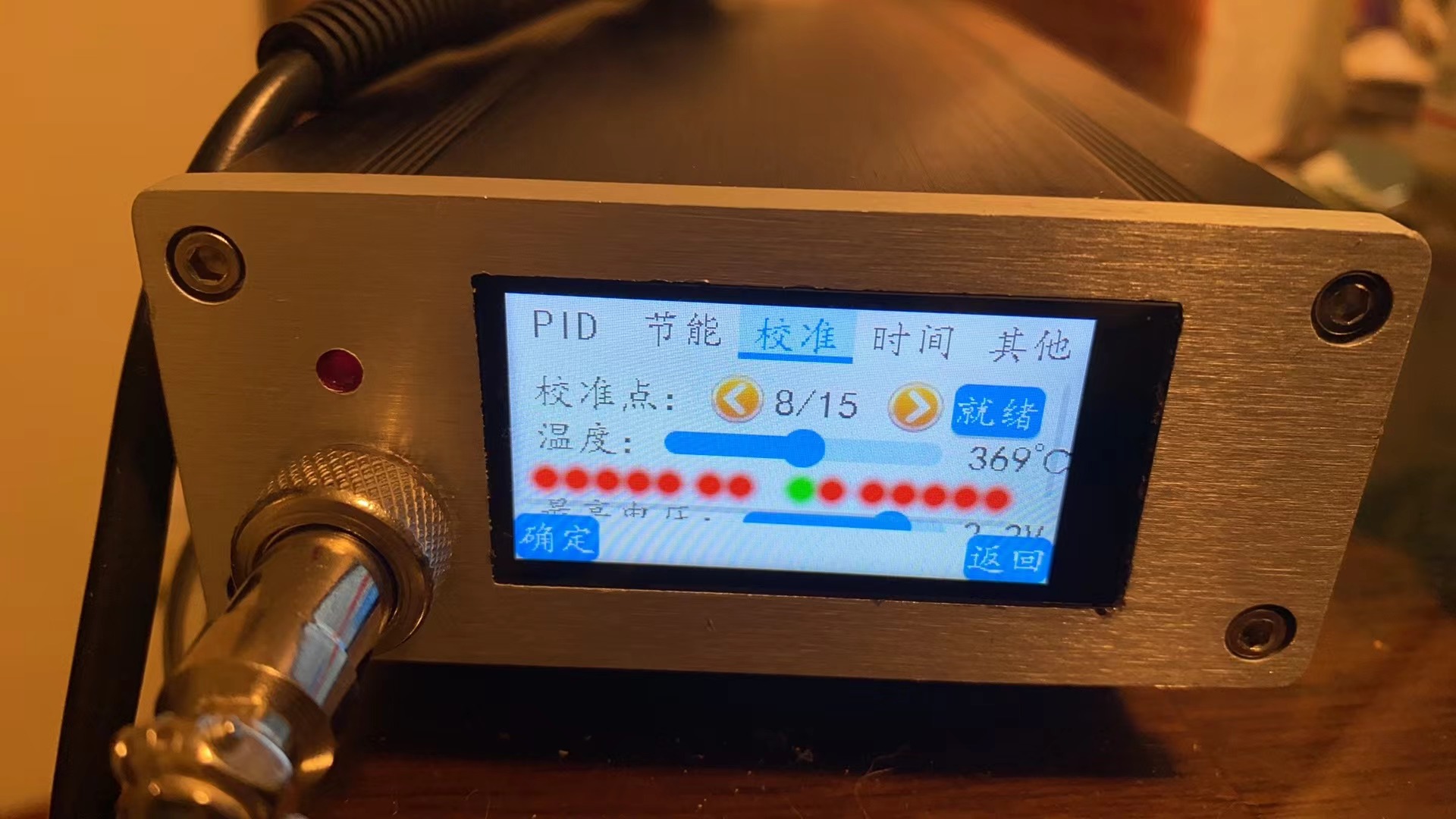
2. Both normal operation and calibration modes employ 2-segment PID control: rapid temperature rise, fast temperature recovery, and accurate temperature readings. The four PID algorithm parameters for both modes are fully accessible and can be directly adjusted on the touchscreen UI, allowing for direct observation of the PID temperature control effect. This provides a direct visual experience for those learning PID algorithms.

3. Equipped with IP2368, LTC2944, and INA226 for a total of 3-channel power parameter monitoring: You can directly view the various working power parameters of USB, battery, and soldering tip. If cost considerations are taken into account, LTC2944 or INA226 can be directly omitted without affecting the operation of the main software, but the monitoring function will be reduced.
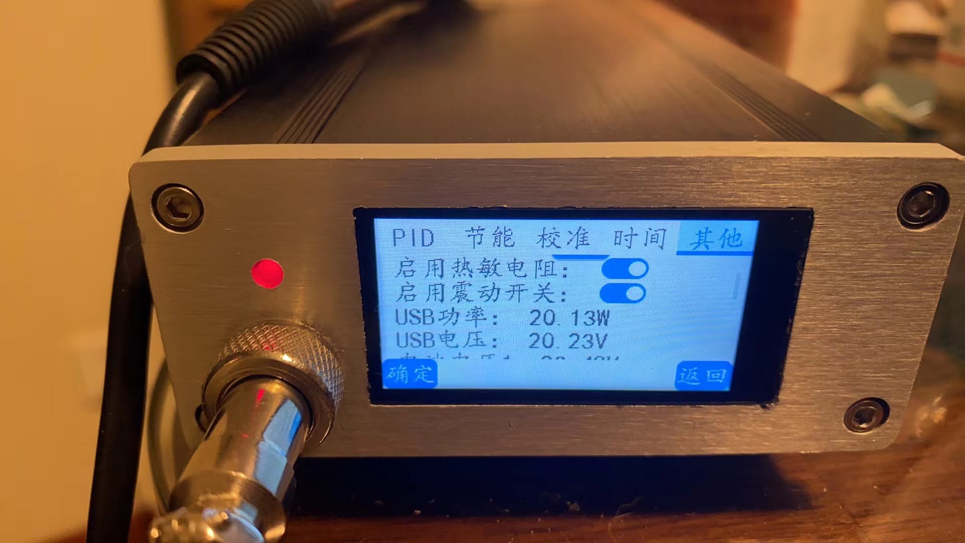
4. Multi-channel soldering tip status monitoring: The working status of the soldering tip is monitored using multiple monitoring methods such as NTC resistors, thermocouples, and reed switches. The insertion, removal, and handle placement status of the soldering tip are detected to achieve energy saving and other functions.
The main algorithms used are:
1. Kalman filter. The output voltage of the thermocouple is filtered to achieve a stable output effect.
2. Polynomial fitting algorithm. (1) Referring to the polyfit polynomial fitting algorithm, the relationship between the output voltage and temperature of the thermocouple is fitted with a third-order polynomial. (2) Referring to the polyfit polynomial, the relationship between battery voltage and power is fitted with first-order and third-order polynomial piecewise.
The power calculation algorithm is relatively complex. It is roughly calculated once by fitting when the machine starts up. During normal operation, due to the large fluctuation of battery voltage, voltage estimation can no longer be used. Instead, the power calculation is performed by using the LTC2944 coulomb meter. During operation, the battery capacity must also be continuously corrected according to the actual usage of the battery using the capacity correction algorithm.
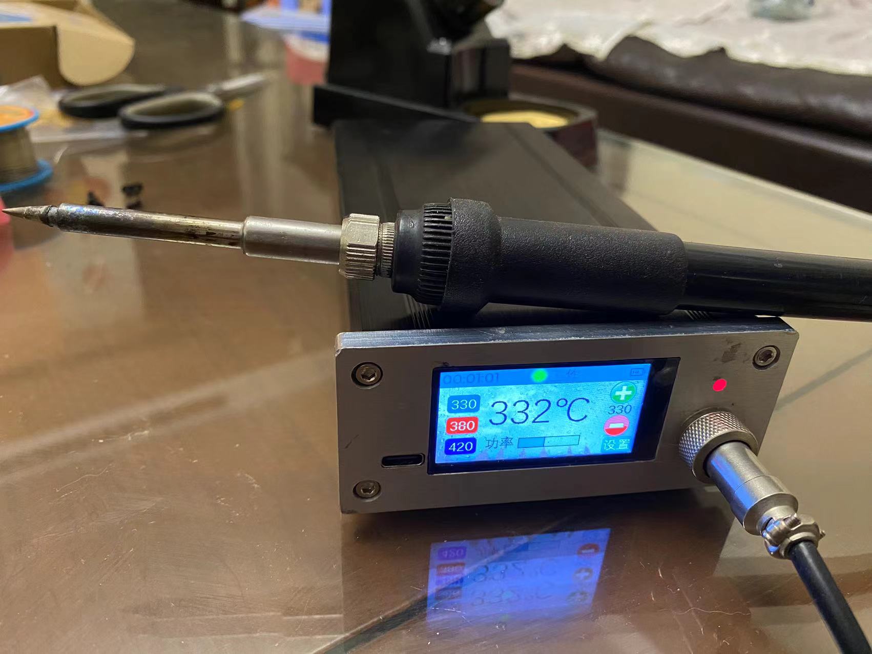
IV. Physical display


V. Attachment content
Attachment 1: CNC file of the front panel (masterCAM2023 version) Attachment 2: Code repository https://gitee.com/fat0x/T12-Touch
VI. Precautions
1. This project is an open source project and is only for research and learning purposes. It is not suitable for any commercial purpose. Please abide by the relevant open source agreement. If any circuit diagram, PCB, source code or other commercial purposes are used in this project, the intellectual property disputes and product safety issues are not related to the uploader of this project.
2. The charging board and the main control board are connected by I2C. The charging board has two chips, IP2368 and LTC2944, which communicate with the main control board through the I2C bus.
(1) There are many models of IP2368. Please refer to the chip manual. Models with I2C functionality and those without I2C functionality are compatible except for the pins of the I2C bus section, and both can be used. If a model without I2C functionality is used, the charging parameters cannot be read. Also note the difference in the soldering of components on the peripheral I2C bus section of the charging board between models with and without I2C functionality.
(2) The LTC2944 is used for monitoring the voltage, current, power, and power of the lithium battery, and some functions are duplicated with the IP2368.
(3) The whole machine can be used without a lithium battery, but with a 24V switching power supply. In this case, the software will not have data from IP2368 and LTC2944. However, the main control board has an INA226 to monitor the power data of the main control board, which is used as a reference for the working conditions of the soldering iron tip.


 京公网安备 11010802033920号

 MQ1N5934AUR-1TR


