This board
exposes and connects all pins of a 24-pin Type-C male and female connector (except VCC, for easy connection of an ammeter). Because it's essentially a pass-through, it theoretically supports all charging protocols and can be used for low-cost current measurement (although 24-pin Type-C connectors aren't cheap).
The drawback is that VCC must be connected to function as an adapter board.
It has been tested and verified; it runs at full speed when connected to a 10Gb/s hard drive enclosure, and there is no significant temperature rise even when exceeding 5A current.
The process chosen
is JLC04161H-3313 lamination structure;
the Type-C interface uses a clamp-type design. Depending on the selected interface, the board thickness can be 0.8mm or 1mm, generally 0.8mm. 1mm may require manually prying open the pins, but it is also easier to fix and solder.
Note:
For high current, it is not recommended to use pin headers (although theoretically a single pin header can handle 3A). I reduced the diameter of the solder pads to 0.8mm for easier pin header fixation during soldering. For wire bonding, you can enlarge the solder pads yourself.
The casing is not connected to ground. If a connection is needed, use a 0Ω resistor or a lump of solder. To utilize the casing for current carrying, the solder needs to be connected to the pins connected to the casing; otherwise, the casing and ground are only connected through a single 7mil wire. See the PCB diagram for details.
For versions without high-speed lines, the high-speed line pad is GND, and the silkscreen has not been adjusted.
(The board size could actually be reduced, but I'm too lazy to adjust it.)
Performance testing and
transmission speed testing
were conducted using a 9210B controller hard drive enclosure with RC20. 512GB RAM, PC 5600X, USB 4.0 The C-to-C cable connects to the 10Gb/s USB-C port;
a direct connection means the cable plugs directly into the hard drive enclosure, while an adapter connects the cable to an adapter board and then
to the hard drive enclosure. The adapter board used is the one without the high-speed port exposed (this board will be used by default in subsequent tests). The board with the high-speed port exposed can also be used without connecting the RX/TX pad headers; it was not tested with the headers connected.
The results of two tests are as follows, and performance can be considered unaffected. The

overcurrent capability test
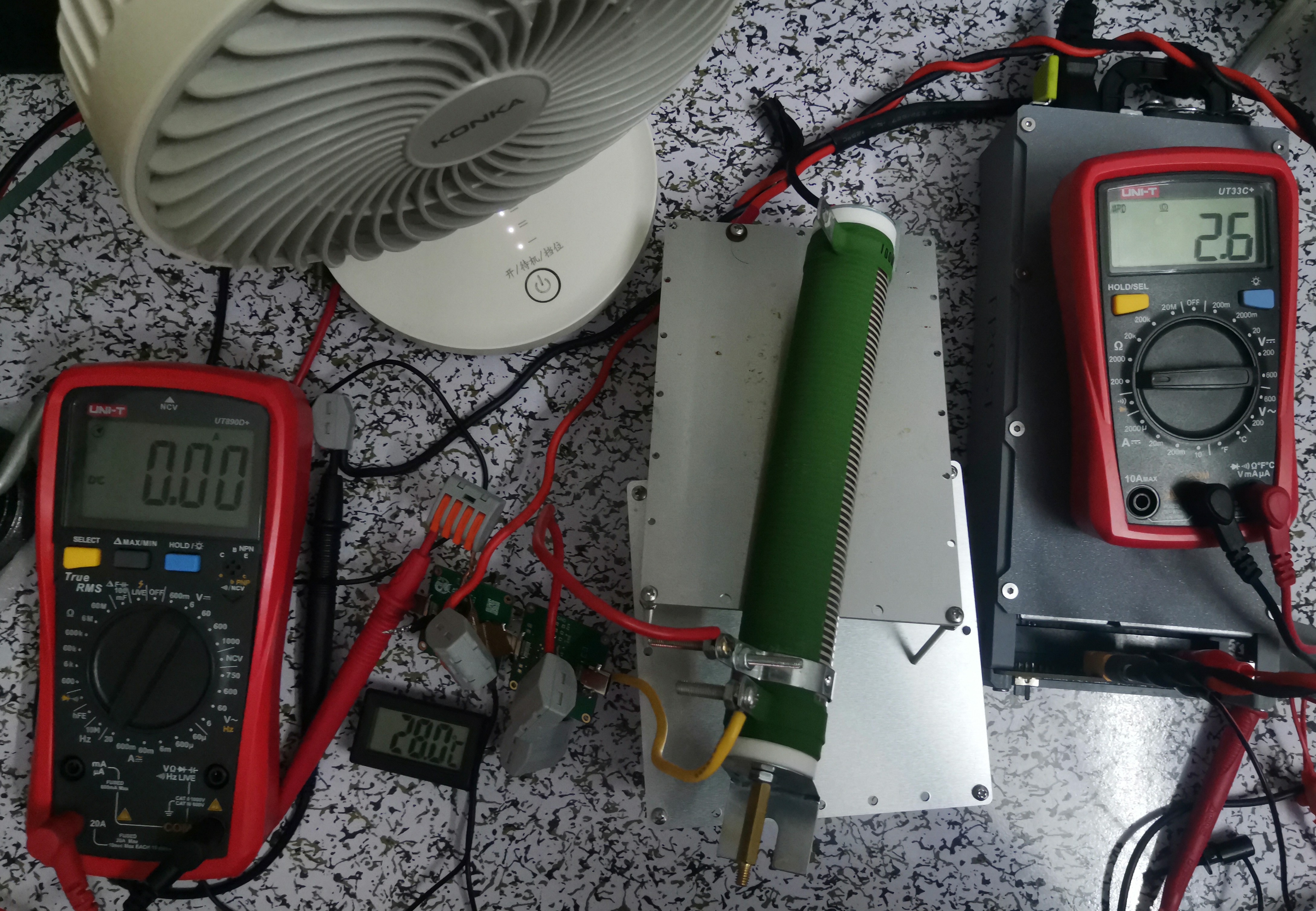
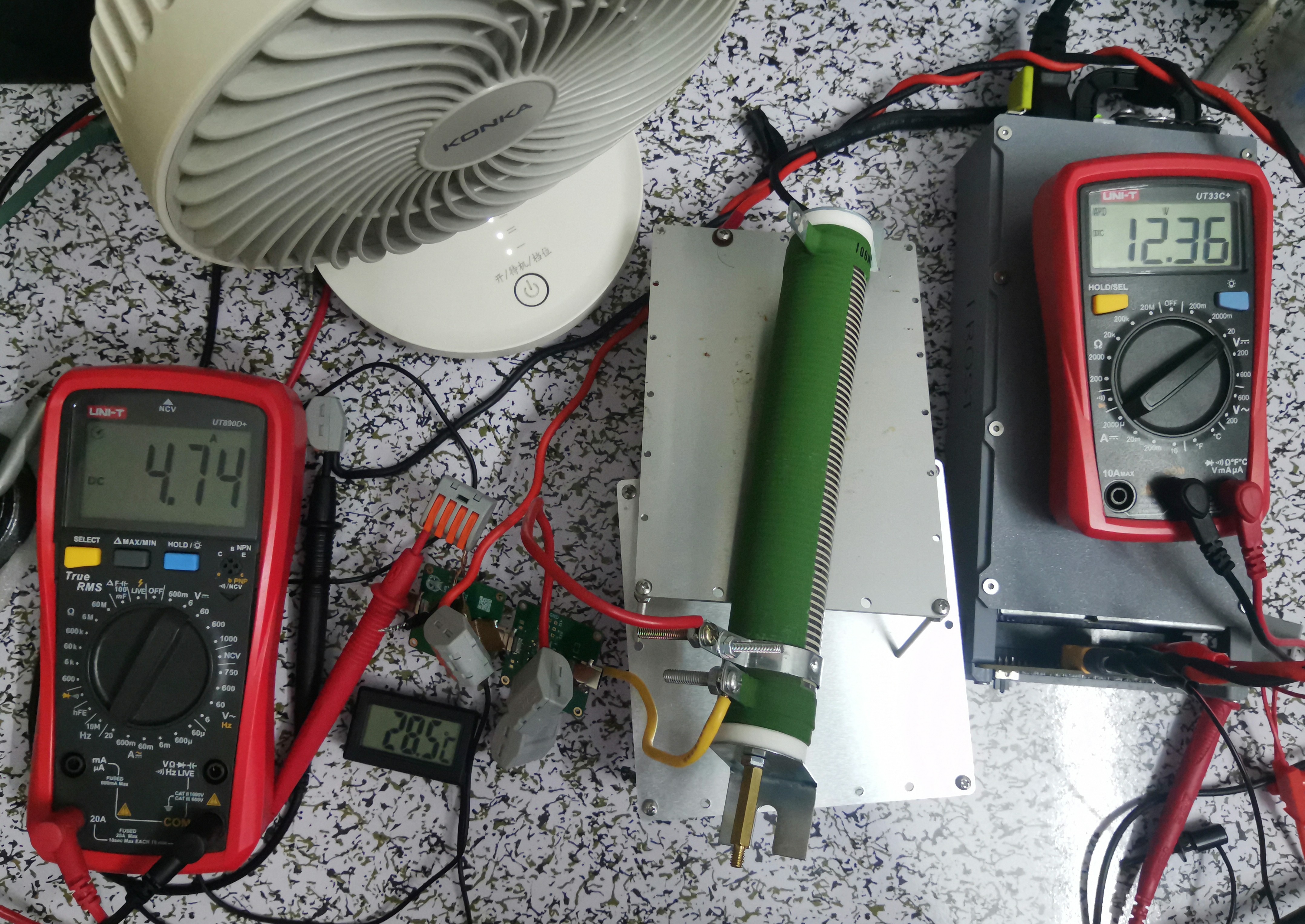
used a 12V power supply (450W) with a power resistor as the load. The target current was 5A, but after connecting all cables, the measured resistance was 2.6Ω, and the resistance increased after heating, ultimately preventing the current from reaching 5A. The
overcurrent capability was judged based on the temperature sensor. Since the air conditioner was just starting to cool during the test, the ambient temperature can be estimated at 26.5-27.5℃. The test duration was a few minutes (the load was a bit too much, the total resistance was too high, only a small portion heated up, and the heat dissipation was poor). It's also possible that airflow blew onto the adapter board, but the final temperature rise was not high. Conservatively, it can be considered to support PD for a short period. 100W current;
during testing, the wire was directly inserted into the adapter board pads. It's uncertain how the overcurrent capacity would be if a header pin and jumper cap were used.
The following image shows the resistance before power-on:
The following image shows the current during testing:
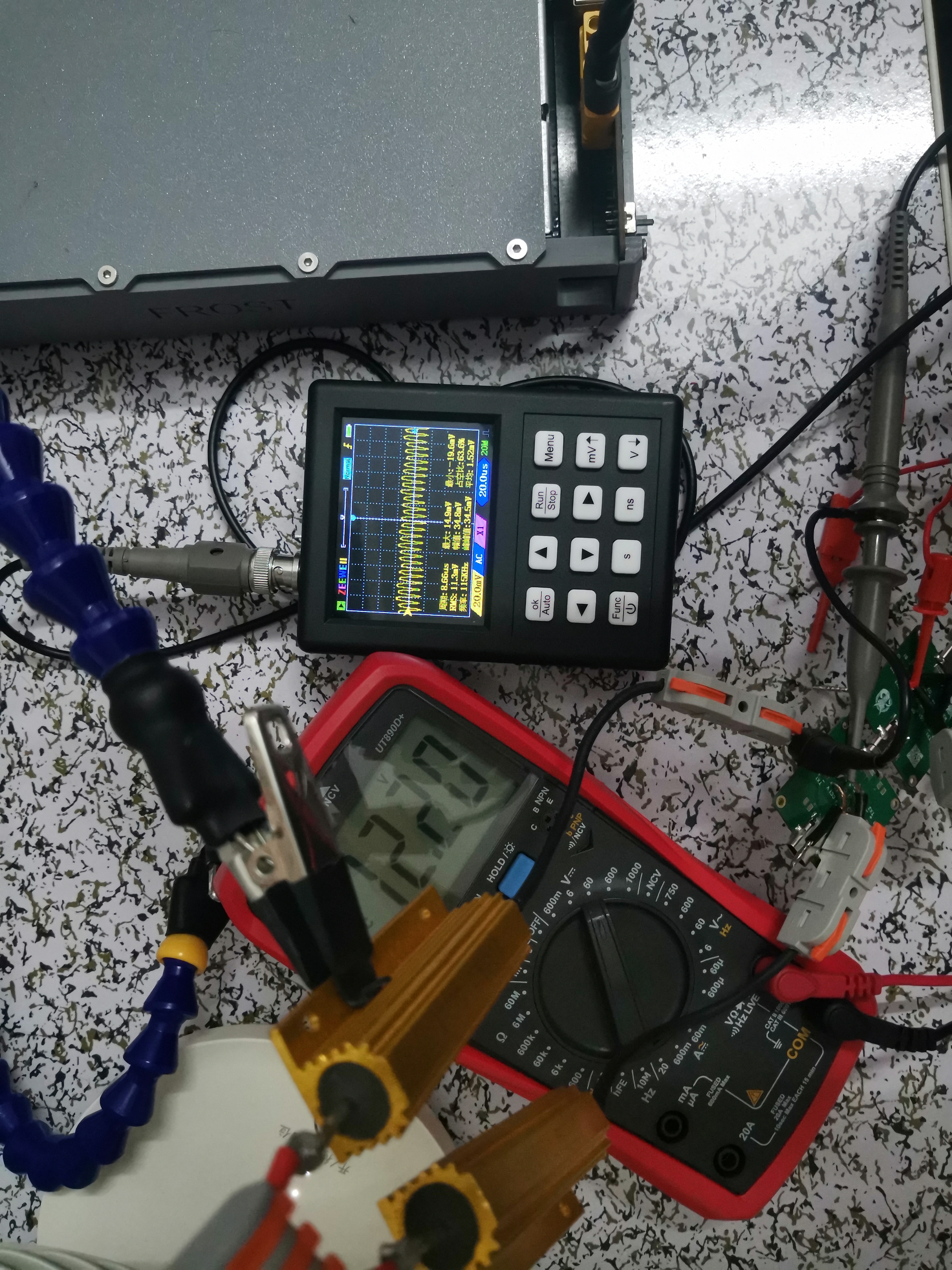
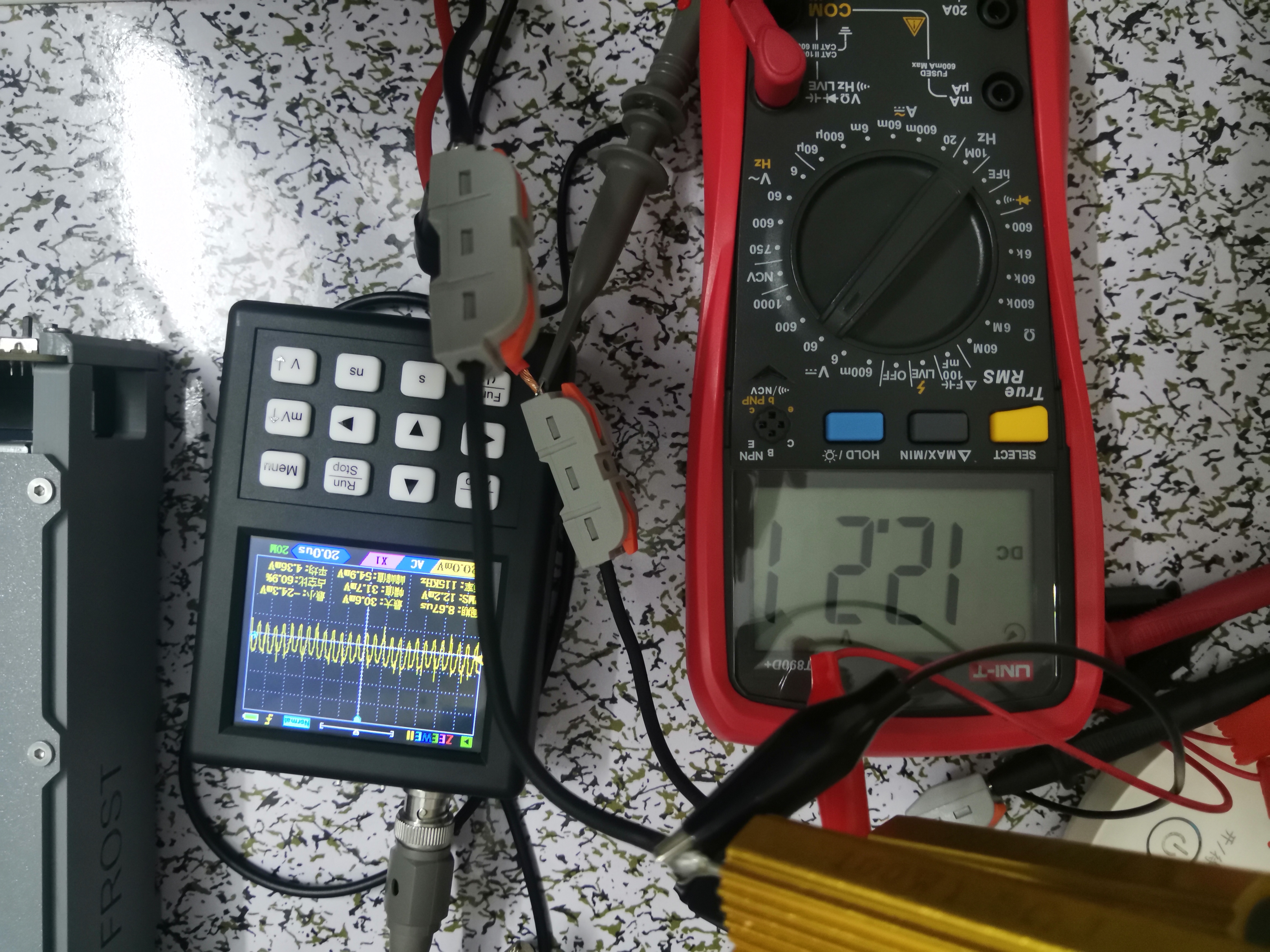
The ripple test
still used the above power supply, with two 1.5Ω resistors in parallel. The actual current was less than 4A. The ripple was tested through the adapter board and directly connected. The oscilloscope connection was not standard, so the results are for reference only. The final minimum peak-to-peak values were similar, while the maximum peak-to-peak value was slightly lower after connecting the adapter board.
It's an RC filter; my excellent PCB design has its own RC filter (not really)
. The following image shows the ripple using the adapter board:
The following image shows the ripple of the direct connection:
PDF_TypeC Interface Female to Male Adapter Board 24pin.zip
Altium Type-C female to male adapter board 24pin.zip
PADS_TypeC interface female to male adapter board 24pin.zip
BOM_TypeC interface female to male adapter board 24pin.xlsx
92109
electronic


 京公网安备 11010802033920号

 18122C103KAZ9A


