I. Top (Pin)
This project is licensed under the "CC BY-NC-SA 3.0" open-source license and is not permitted for commercial use. Please indicate the author and source when reprinting. Please consciously abide by the open-source license.
II. Project Revision
Rev. 1.1
Bug Fixes:
1) Fixed the issue with the MDL7601 schematic symbols (USB data differential pairs were reversed);
2) Fixed the issue of the multi-function switch not working properly and the GPIO pull-up problem.
Rev. 1.0
Initial Release
III. Project Introduction
This project is a high-specification digital decoding headphone amplifier that supports USB Audio, coaxial, and Toslink® (optical audio) inputs and supports mode switching.
IV. Function Implementation The
main functions of this project rely on the MDL7601-9018_A1 high-definition digital audio module, equipped with the CT7601CR high-performance USB audio chip and the ES9018K2M high-fidelity audio DAC combined with a low-noise audio op-amp, thereby achieving high-quality audio playback.
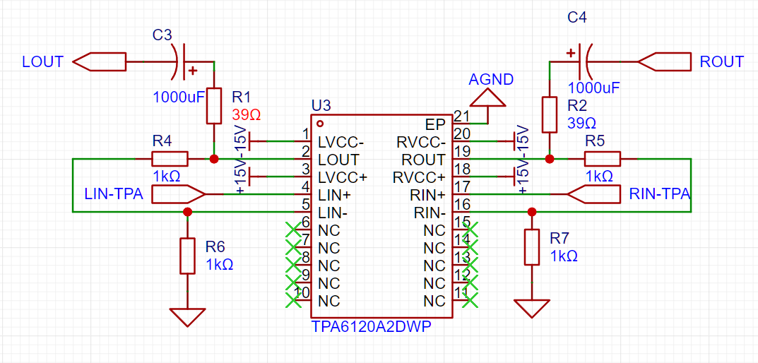
The headphone amplifier functionality relies on TI's TPA6120, a high-fidelity headphone amplifier with a high output power of 1.5W, a dynamic range of 128dB, total harmonic distortion and noise (THD+N) below -105dB, and low input noise (typically 0.9μVrms). These features make it suitable for professional audio equipment and high-end music players.
Auxiliary function modules include power supply, multi-function switch, status indicators, input/output ports, and output squelch.
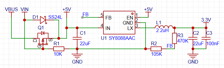
1) The power supply section includes the headphone amplifier power supply and the digital I/O interface power supply. The headphone amplifier power supply uses a Boost converter + charge pump combination to generate the positive and negative power supplies required for the headphone amplifier to operate (due to diode voltage drop, the negative power supply voltage will be about 0.3V lower than the positive power supply, which is normal). This circuit is shown in the diagram below.
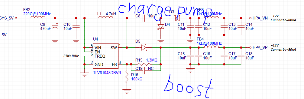
The digital I/O section has no special power supply requirements and uses an LDO to provide 3.3V to the I/O circuit.
2) The multi-function switch uses a single switch to adjust volume and switch modes. Tossing the switch left decreases volume, tossing it right increases volume, a short vertical press switches the input source, and a long press for one second switches the filter style*. When the power is off, pressing and holding the switch vertically while connecting to a computer switches the USB Audio Class (to UAC 1.0 mode, supporting Windows 10 and earlier systems and the Switch).
*There are 3 filter styles, see the table below for details:
Filter Mode
Filter Name
Mode 1
Linear phase fast roll-off
Mode 2
Linear phase slow roll-off
Mode 3
Minimum phase fast roll-off
3) Status indicators are provided by dual-color LEDs, supporting input mode indication, volume status indication, and filter mode display.
The status indicators are shown in the table below:
Source Mode
Locked Status
LED Display
USB Audio
N/A
Purple constant on
Toslink
input signal lock
Red constant
on input signal unlock
Red slow flashing
Coaxial
input signal lock
Blue constant on
input signal unlock
Blue flashing
Filter mode
LED display
mode 1, mode 2
Purple light flashes once
Mode 3
Purple light flashes twice
Executed volume level
LED display
Maximum (60 levels) and minimum (0 levels)
Purple LED flashes once
4) Input/output ports include USB Type-C interface, Toslink interface, coaxial digital audio interface, and headphone output interface. The Type-C interface is used to connect USB host devices such as computers, serving as power supply and audio streaming; the Toslink interface is used for S/PDIF optical input; the coaxial interface is used for S/PDIF digital audio input; and the headphone interface is used to output the analog audio signal amplified by the headphone amplifier.
5) The output mute section implements the headphone output mute function when powering on and off. It uses the detection of whether the VBUS voltage reaches the mute threshold to control the relay to open and close, thereby achieving output mute.
V. Main Parameters
1) Default power-on operating mode: USB Audio (UAC 2.0), with power-off memory function;
2) Power input: 4.8-5.2V DC, current 500mA-1A;
3) S/PDIF coaxial input level: 300mV-3.3V (termination impedance 75Ω);
4) S/PDIF optical input: Toslink interface;
5) Headphone output 0dBFS level: 1.8Vrms;
6) Headphone output frequency response: 20Hz-50kHz (sampling frequency 192kHz);
7) Headphone output frequency response flatness: +0.02, -0.2 (20Hz-20kHz);
8) Headphone output signal-to-noise ratio (SNR): >118dB;
9) Headphone output dynamic range (DNR): >118dB;
10) Headphone output total harmonic distortion + noise (THD+N): -105dB
VI. Functional demonstration (Demo)
Physical display

PDF_USB+Coaxial Input Decoding Headphone Amplifier.zip
Altium_USB+coaxial input DAC/amplifier.zip
PADS_USB+Coaxial Input Decoder Amplifier.zip
BOM_USB+Coaxial Input Decoding Headphone Amplifier.xlsx
90962
CloseMV - The authentic OpenMV4 experience [doge]
A machine vision module costing just over 50 can be flashed with the latest official OpenMV4 firmware, allowing you to experience OpenMV4 exactly the same way with an H750!
I. Project Introduction
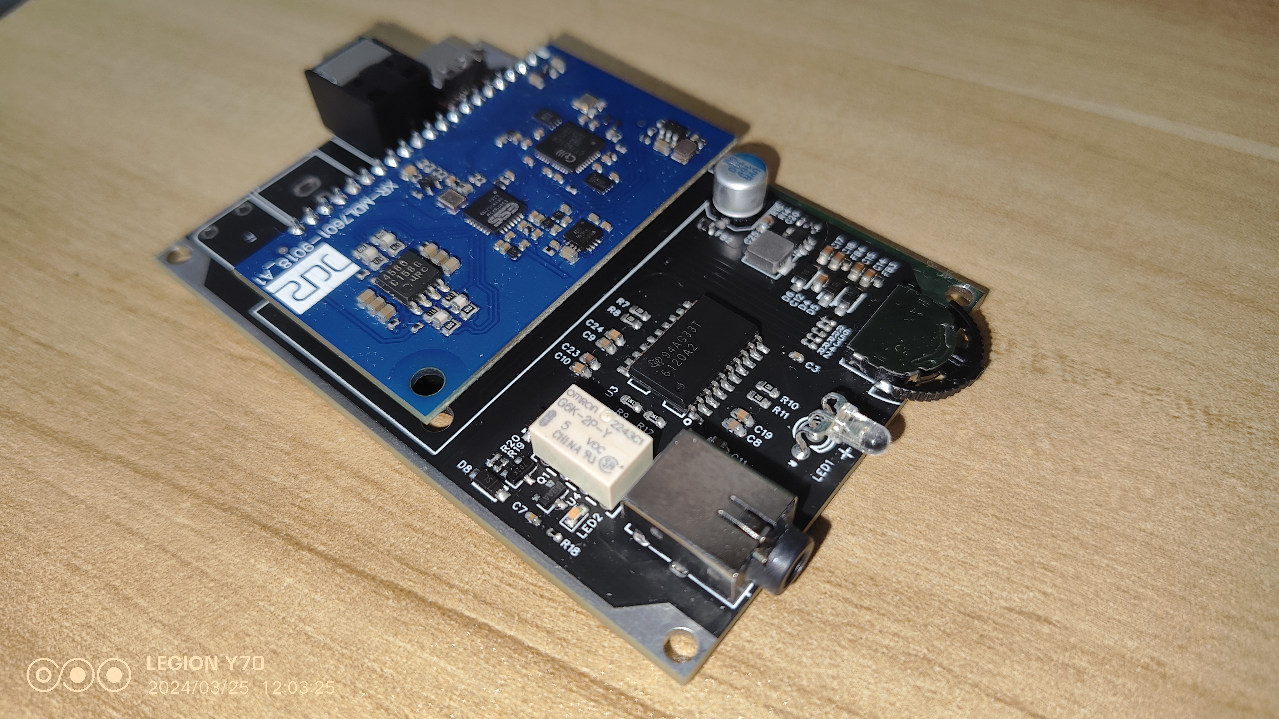
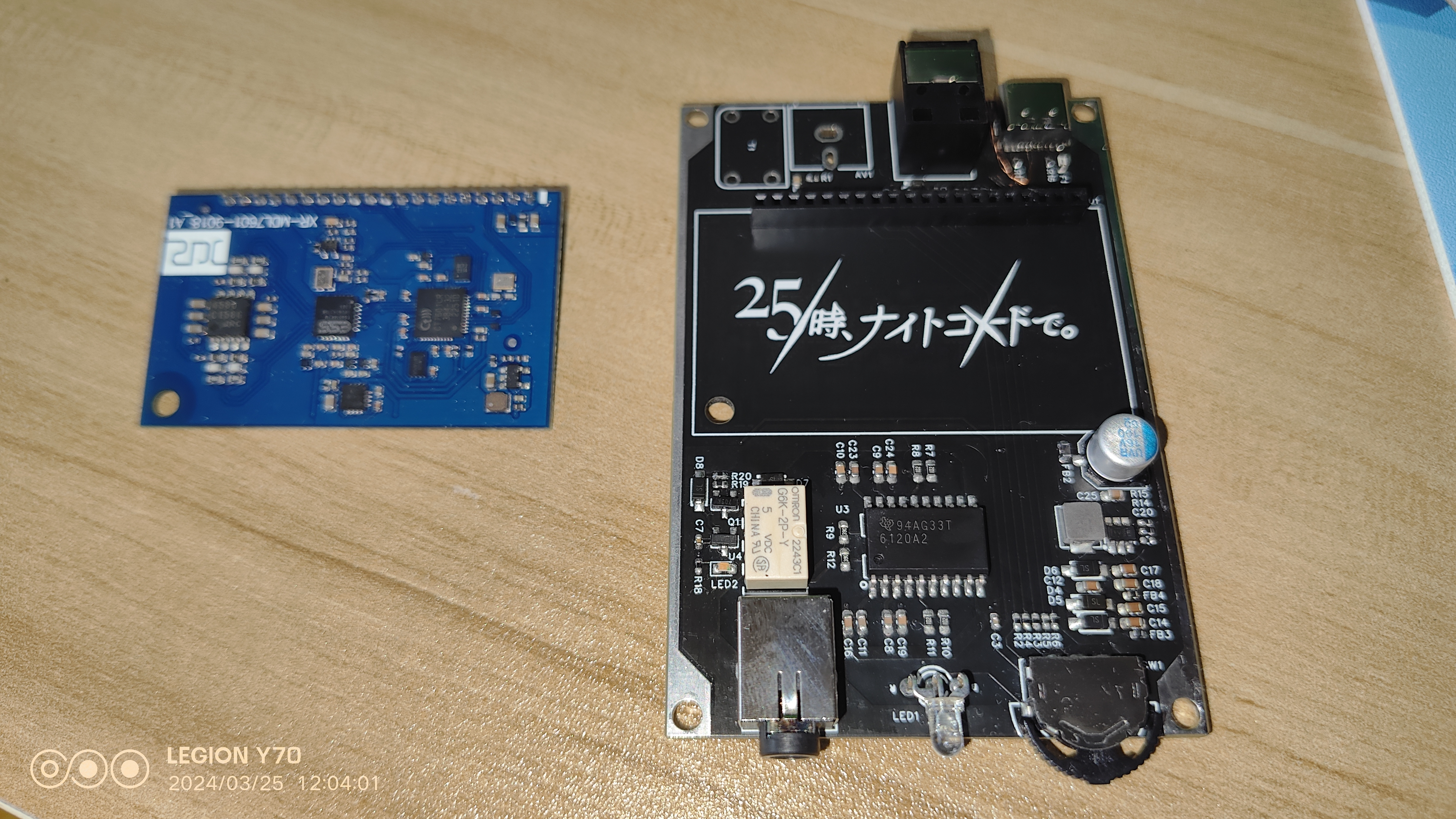
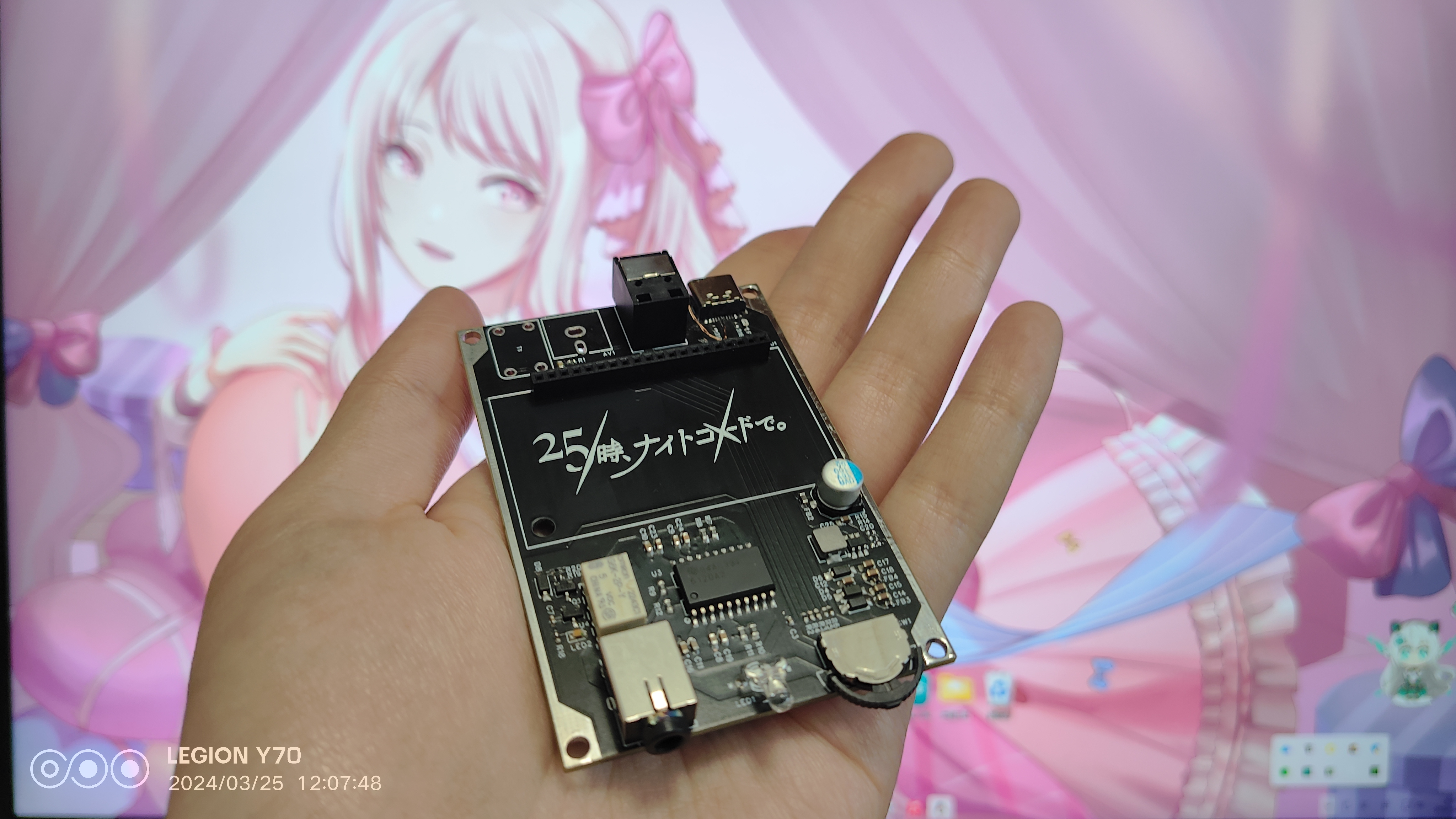
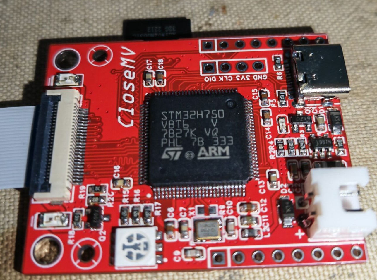
This project references the open-source project OpenMV, summarizing common causes of OpenMV burnout in various competitions due to improper use. The schematic diagram has been partially improved, and the circuit has been redrawn. This project includes a CloseMV core board, an OV5640 camera module, a 1.8-inch ST7735 display module, and an ATWINC1500 wireless module. Because the STM32H750VBT6 has a large amount of unverified space, the actual ROM size is much larger than its stated size. The main control chip has been tested and can use both STM32H750VBT6 and STM32H743VIT6. Functionally, CloseMV is compatible with the latest official OpenMV4 firmware. The cost of the motherboard and camera is kept below 50. The components in the project use a minimum 0603 package for safe use. (The main controllers used are all V-version; some vendors sell down-clocked Y-version chips that cannot be used in this project.)
The following figures show the boards using H750 and H743, and the back of the boards.
II. Overall Design Block Diagram
The core circuit design block diagram is shown below:

III. Introduction to Some Circuits and Precautions
For ease of use, some circuits are introduced below
. 1. For system power supply, the development board uses a PMOS transistor and a Schottky diode to form a dual power supply switching circuit. The VBUS network is the Type-C power supply, and the VIN network includes power supply using the VIN pin on the development board and the XH 2.54mm lithium battery interface on the board. When both power supply networks are connected to the system at the same time, the VIN network will pull the gate of the PMOS transistor high to cut off the VBUS network, and at the same time, power will be supplied to the system through the Schottky diode, allowing the USB to only perform data transmission and reducing the load on the USB interface. In summary, the system power supply priority is VIN > VBUS. After selection and judgment, the circuit will enter the DC-DC step-down circuit to output 3.3V to power the system. Due to the presence of Schottky diode D1, the VIN pin on the development board cannot be used as an output when only the Type-C data cable is plugged in for power supply!
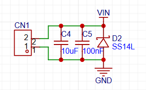
2. Based on my observation of the common OpenMV burnout phenomenon, many people burn out OpenMV by reversing the power supply. Therefore, a Schottky diode is added specifically to prevent reverse connection of the VIN network. The position is directly above the lithium battery interface.
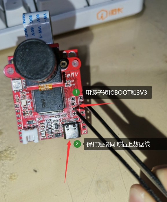
3. Regarding the reset and boot mode settings of the development board, the development board does not have a BOOT button or RESET button. The circuit adopts a power-on reset and direct program startup from the chip. To enter DFU download, you need to use a wire or tweezers to pull the BOOT pin high.

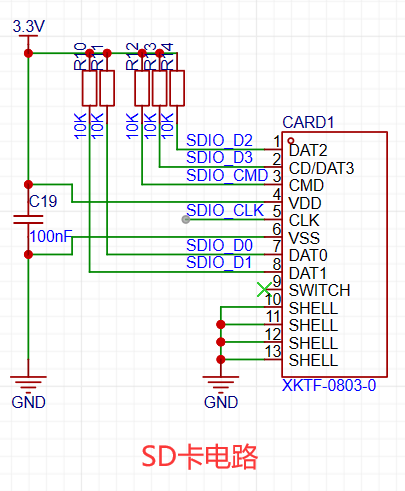
4. In the SD card circuit, since I am using a short-body TF card socket, the SWITCH pin is used to detect SD card insertion. When an SD card is inserted, the SWITCH pin will be pulled to a high level. However, the SWITCH pin of the TF card socket used by OpenMV is pulled to a low level after power-on. To ensure compatibility with the official firmware, I pulled the PD0 pin of the internal SWITCH connector low, while leaving the SWITCH pin of the TF card slot floating. This prevents the development board from failing to read the SD card. Furthermore, the official firmware code only detects the SD card briefly upon power-up; if no response is received within a timeout, it defaults to no SD card being inserted. Therefore, from a functional perspective, this circuit change has no impact on actual use. This point is included to remind other developers of a potential pitfall when replicating or designing their own SD card circuits—different SD card slot models may have different pin output values for insertion detection.
5. The camera interface uses a DVP parallel bus and connects to the STM32 main controller via a 24-pin FPC cable, facilitating integration into more demanding application scenarios. In the circuit design, I have already ensured the DVP interface data lines are of equal length. To guarantee signal integrity, the 1.5V and 2.8V power supplies required by the camera are concentrated on the camera module. Only the 3.3V network and GND coexist with the parallel data lines on the ribbon cable, reducing interference between different network signals. If the camera cannot be recognized, please check the FPC socket and the soldering of the chip for solder bridging. The circuit design itself is not flawed. Because the DVP interface is a parallel data interface, its anti-interference capability is not as strong as differential signal interfaces like MIPICSI. Therefore, it is recommended that the FPC ribbon cable be no longer than 20cm; otherwise, snowflake-like noise may occur. The camera can be purchased separately with an M12 lens mount to accommodate different lenses. It can be fixed to the development board via M2 screw holes.

IV. Firmware Burning Steps:
The development board can be firmware-burned using STLink via the SWD interface, or it can be connected to a computer via a Type-C data cable and downloaded in DFU mode. Because the STM32H750 has a large amount of unverified space, the actual ROM size is much larger than its stated size. If the STM32H750 is used as the main controller of the development board, firmware can only be downloaded via DFU mode. The following firmware burning steps only describe the DFU download method.
1. Download the firmware burning tool STM32CubeProgrammer from the ST website. Download link: [Click here]. Need specific instructions on how to download it? Next, just do it one step at a time.
2. Use tweezers to short-circuit the BOOT and 3V3 pads, pull the BOOT high, and then insert the Type-C data cable. Before this, I still suggest you use a multimeter to check the board. Burning the board is a minor issue, but burning your computer is a different story.
3. Open Device Manager and you will see an additional DFU in FS Mode, indicating that the chip has entered DFU download mode. After that, you can remove the tweezers used to pull the BOOT pin high.

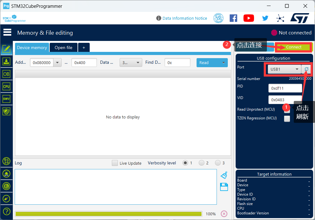
4. Open STM32CubeProgrammer. First, click the refresh button. The recognized USB devices will appear. Select the connected STM32 and click the Connect button to connect the computer and the chip to obtain chip data.
5. After successful connection, it will be displayed as shown in the figure below. Since my chip has been programmed once, the content displayed in the data register may be different from others. Please ignore this.

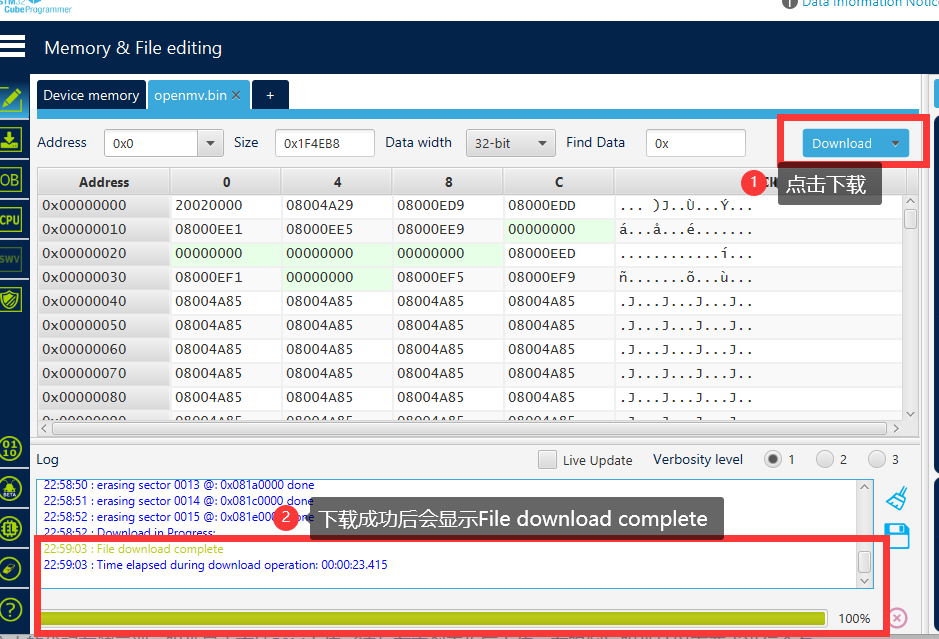
6. Click Open file to find the location of the OpenMV4 firmware. The bin file is usually located in [your own OpenMV path OpenMV]. If you can't find it in the folder [IDEshareqtcreatorfirmwareOPENMV4], see the attachment at the bottom.

7. Click Download and wait for the download to complete. A successful download will look like the image below.
8. After downloading, disconnect and reset the device, then power it on and connect to the OpenMV IDE.
V. Physical Demonstration
The following demonstrations all use the H750+OV5640 core board configuration
. 1. Color block detection demonstration
2. LCD screen display case demonstration
3. WiFi image transmission case demonstration
Video demonstration see the last attachment.
VI. Attachment Contents
Attachment 1: openmv.bin Attachment 2: BOM (Component purchase is for reference only)
Color Block Search Demonstration.mp4
WiFi image transmission demonstration.mp4
LCD module display.mp4
Attachment 1: openmv.bin.zip
Appendix 2: BOM (Components purchase information for reference only).zip
PDF_CloseMV - The Authentic OpenMV4 Experience [doge].zip
Altium_CloseMV - The authentic OpenMV4 experience [doge].zip
PADS_CloseMV - The authentic OpenMV4 experience [doge].zip
BOM_CloseMV - The authentic OpenMV4 experience [doge].xlsx
90963
Based on ESP32 driver for ceramic crystal pool serial port screen
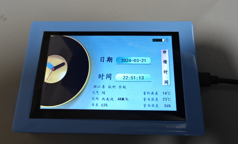
This device uses an ESP32-driven ceramic crystal pool serial port screen to display indoor temperature and humidity, battery power information, weather forecast temperature information, etc.
Project Description: This project
uses an ESP32-driven Taojingchi serial port screen to display indoor temperature and humidity, battery power information, and weather forecast information.
Project Functions:
1. The entire system's UI is designed and developed by Taojingchi's official host computer.
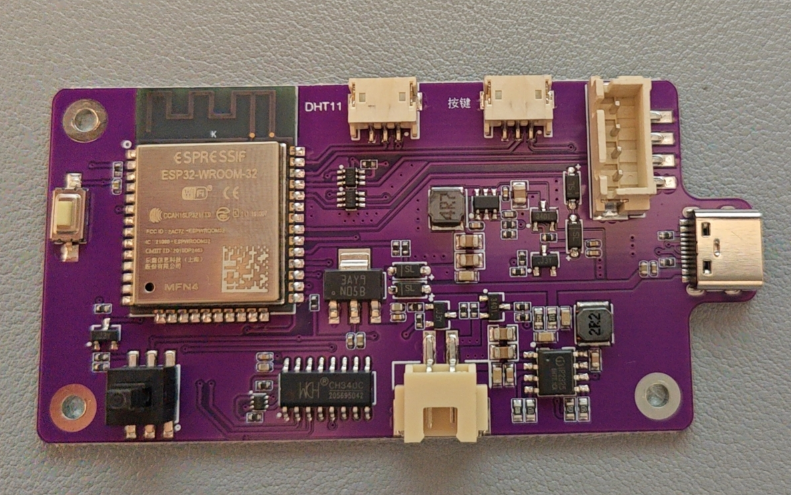
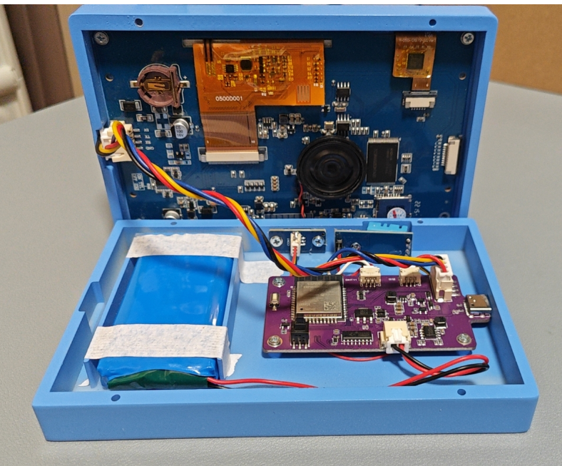
2. The system has a built-in 7.4V battery and can be powered by the battery or USB.
3. The entire system includes a two-cell lithium battery charging system, a DHT11 circuit, a charging detection circuit, an ESP32 download circuit, a DC-DC (5V) LDO (3.3V), battery voltage sampling, a serial port selection circuit, and a button power-on circuit.
4. Currently, it only displays relevant information and provides some simple human-computer interaction. More functions can be developed based on the serial port touchscreen in the future.
Project Attributes:
This project is being publicly disclosed for the first time and is my original work.
Project Progress:
2024-03-21 Initial completion of the casing, PCBA, and program design; initial firmware debugging completed.
Design Principles:
1. Supports mobile phone network configuration and simultaneous configuration of weather-related information. The configuration information can be saved and only needs to be configured once.

2. The device has a startup sound and a sound effect when the screen is tapped.
3. The device's home screen displays the city location, date, time, geographic location, real-time weather, indoor temperature and humidity, and battery level. A charging icon will appear when the charger is plugged in.
4. The secondary page currently only features a future weather function and system settings.

5. Future weather displays the weather for the next three days.

6. System settings allow users to adjust screen brightness and voice volume. Other
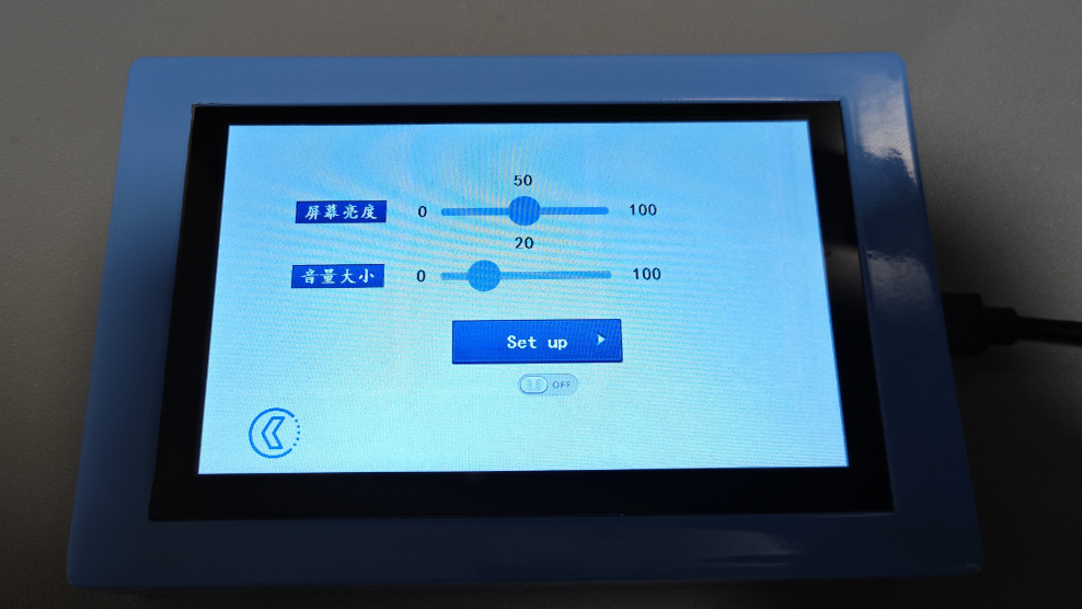
features are shown in the physical product demonstration .
Reset Network Configuration.mp4
Booting up.mp4
TOP-0304.stp
BOT-0304.stp
weather_screen_animation_v2.zip
PDF_Based on ESP32-driven ceramic crystal pool serial port screen.zip
Altium_ESP32-based Ceramic Crystal Pool Serial Port Screen.zip
PADS_ESP32-based Ceramic Crystal Pool Serial Port Screen.zip
BOM_Based on ESP32 driver for ceramic crystal pool serial port screen.xlsx
90964
ECHO-PD3.0 Heating Table
The ECHO heating platform uses an STC8H8K64U microcontroller and a CH224K decoy chip. The screen is a 0.91-inch OLED screen with a 45° angle. The heating plate is made of aluminum, and the outer shell is 3D printed. The controller and heating plate are designed to be detachable.
Update Log
March 8, 2024 (
First Release)
March 18, 2024:
1. Updated BOM (Bill of Materials) and simplified production steps;
2. Updated production video.
March 23, 2024:
Updated panel dimensions.
Precautions
: After completing the ECHO heating platform:
Activate
and set the power.
Clean the heating plate
and heat it at approximately 220℃ for 1 minute to oxidize the aluminum substrate surface.
After completing the above steps, the heating plate will have very little solder adhesion.
The optimal operating temperature is 100-240℃, and short-term operation at 300℃ is fine. Due to the insulation material of the aluminum substrate, excessively high temperatures will produce harmful gases and cause irreversible damage!
Open Source License
: This project uses the CC-BY-NC-SA 3.0 open source license, i.e., Creative Commons Attribution-NonCommercial-ShareAlike.
CC: Creative Commons Attribution
-Attribution. You must give appropriate attribution, provide a link to this license, and indicate whether modifications were made (to the original work).
SA: Share Alike. If you remix, transform, or build upon this work, you must share and distribute your contributions under the same license as the original.
NC: Non-Commercial. You may not use this work for commercial purposes.
Features:
The ECHO heating platform uses an STC8H8K64U microcontroller with built-in USB functionality, employing a CH224K decoy chip, supporting PD3.0/2.0. The screen is a 0.91-inch OLED display at a 45° angle. The heating plate uses an aluminum-based heating plate (available in two versions, H50/H34). The casing is 3D printed. The controller and heating plate are detachable for easy selection and modification.
The domestically produced STC8H8K64U chip
features built-in USB hardware, supports software updates
, a Type-C power interface supporting PD3.0/2.0 protocols
, a 0.91-inch IIC OLED screen with three color options
, a 45° angled display for easier data viewing
, a front-mounted dial switch for convenient one-handed operation,
three operating modes: constant temperature mode, curve mode, and reflux mode
, a plug-in design for the controller and heating platform supporting different heating plate sizes
, and a photopolymer 3D printing option for JLCPCB 3D printing, allowing for selection of different colors and materials
for the panel.
The ECHO control board is designed as a double-layer board, showcasing JLCPCB's newly upgraded immersion gold process.
Operation instructions:
The buttons have three positions: up, middle, and down.
The up and down buttons default to an increase/decrease principle.
The middle button is the function button.
1) On the main interface, single-click the function button to turn heating on/off; in constant temperature mode, double-click the function button to switch between current, power, and internal resistance displays.
2) On the main interface, long-press the function button to enter the settings menu.
3) In the settings menu, you can select 5 settings items (PID, Parameters, Mode, Power, and Return) by clicking the up and down buttons.
4) In the settings menu, click the function button to enter the corresponding first-level menu.
5) In the first-level menu, click the function button, select the item to be adjusted, and adjust the corresponding data using the up/down buttons. Click the function button again to return to the first-level menu.
6) In the first-level menu, press and hold the function button or the return button to return to the settings menu. Press and hold the function button or the return button again to return to the main interface.
The
ECHO34 requires printing four PCB files: ECHO-Control Board, ECHO-Cover, ECHO-J34, and ECHO-G34.

Figure 1. PCBs required for ECHO34. The
ECHO50 requires printing four PCB files: ECHO-Control Board, ECHO-Cover, ECHO-J50, and ECHO-G50.
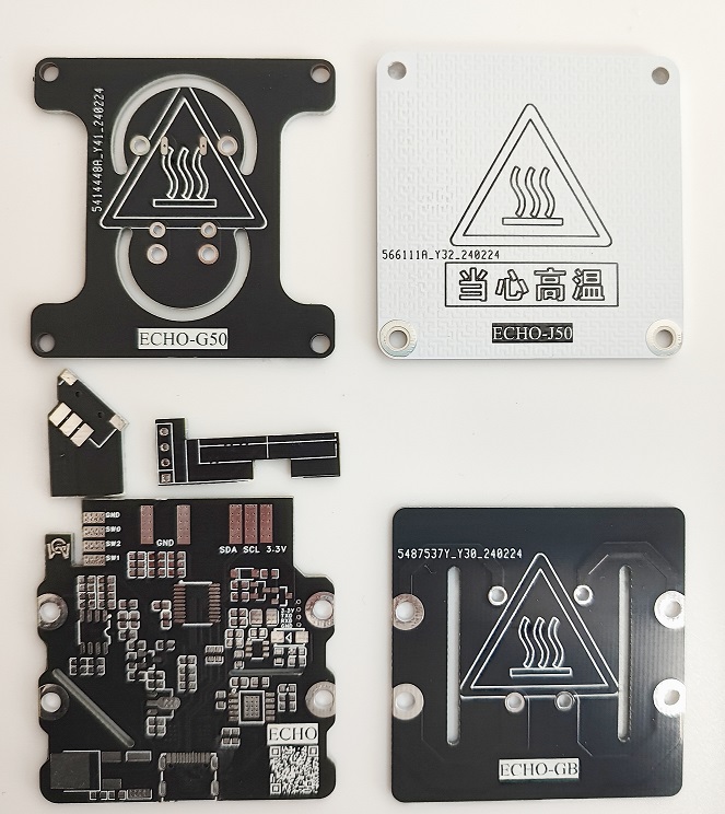
Figure 2. PCBs required for ECHO50.
ECHO-J34 and ECHO-G34 are combined to form the H34 heater.
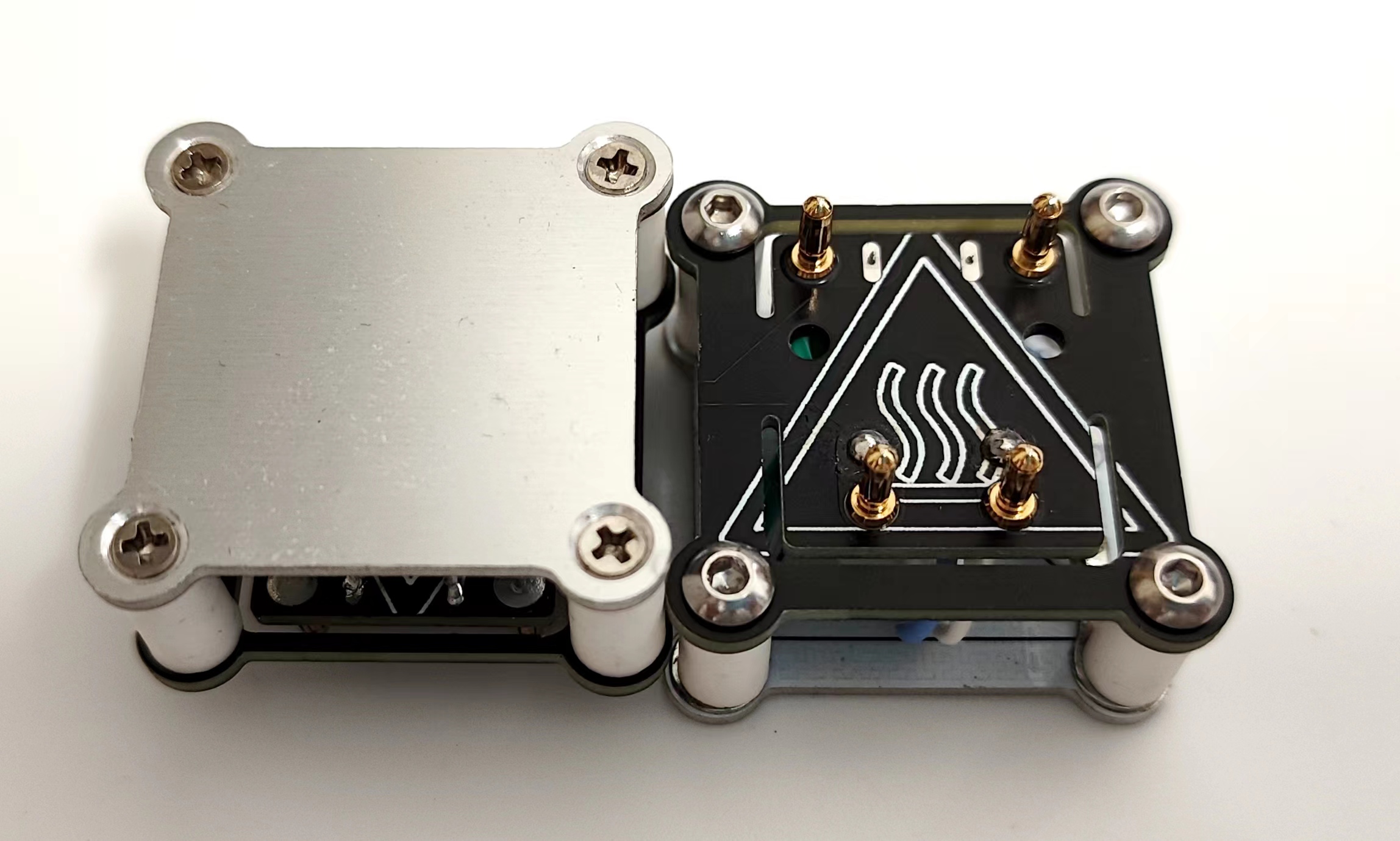
Figure 3. The H34 heater
ECHO-J50 and ECHO-G50 are combined to form the H50 heater.
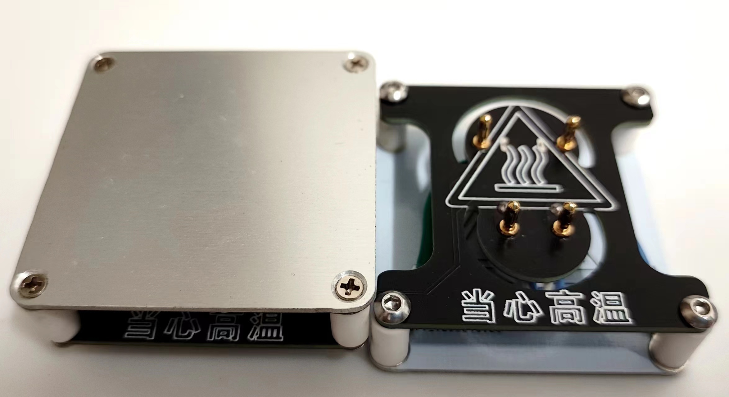
Figure 4. The H50 heater
ECHO-control board and ECHO-cover plate are combined to form the controller.

Figure 5. The controller
can be combined with the H34 heater/H50 heater to form ECHO34/ECHO50 respectively.

Figure 6. Left: ECHO50 Right: ECHO34
Welding and Assembly Tutorial
I. Welding Tutorial
Promotional Video: [Promotional Video] [ECHO-PD3.0 Heating Table]
ECHO-Control Board Welding
: [Part 1] [Control Board Welding] ECHO-Controller Assembly: [Part 2] [Controller Assembly]
ECHO-Heating Plate and Temperature Sensor Assembly: [Part 3] [Heating Plate and Temperature Sensor Assembly]
ECHO-Heater Assembly [Part 1]: [Part 4 (Part 1)] [Heater Assembly]
ECHO-Heater Assembly [Part 2]: [Part 4 (Part 2)] [Heater Assembly]
Temporarily completed.
II. Program Download Tutorial
Ensure correct welding before proceeding!!!
Open the STC-ISP software on your computer. Plug in the Type-C data cable
and press and hold the ECHO heating station function button. Quickly insert the Type-C port of the Type-C data cable into the Type-C port of the ECHO heating station .
If the soldering is completely correct, the STC-ISP software will display "STC-USB Writer (HID1)" (Figure 7).
If it is not recognized correctly, repeat steps b and c until it is recognized correctly

(Figure 7). After successful hardware recognition
, perform the following operation (Figure 8):
Chip model selection: STC8H8K64U
IRC Frequency: 33.1176MHz
EEPROM Size: 3K
Open Program File: PD-heating-stage.hex
Download

Figure 8. Software Configuration
After downloading the program, the screen should display correctly. If not, please check it yourself.
Welcome to join our group for discussion.
Communication methods
: Bilibili: a1298703610
QQ Group: 902453827
Acknowledgements
: Thanks to JLCPCB for the free PCB fabrication! Thanks to Along for providing the activation code!
PD-heating-stage.hex
Bottom shell V2.5.stl
stc-isp-15xx-v6.92D.zip
ECHO-PD3.0 Heating Platform Instruction Manual V1.0.pdf
BOM_ECHO-Control Board_ECHO-Control Board_2024-03-16.xlsx
PDF_ECHO-PD3.0 Heating Platform.zip
Altium_ECHO-PD3.0 heating platform.zip
PADS_ECHO-PD3.0 heating table.zip
90965
Nuclear radiation detector - Geiger-Müller counter
Using the CW32F030 series microcontroller as the main controller, I made a portable, rechargeable environmental radiation detector.
1. Project Description:
This project participates in JLCPCB's "Spark Program" outsourcing track. The topic was jointly released by Wuhan Xinyuan Semiconductor Co., Ltd. and JLCPCB. This project, which took two months, involved the independent design of a portable, rechargeable environmental radiation detector. All
electronic components used in this project can be purchased from Taobao, and all surface-mount components use 0805 packages for easy soldering (except for the thermistor in the charging section).
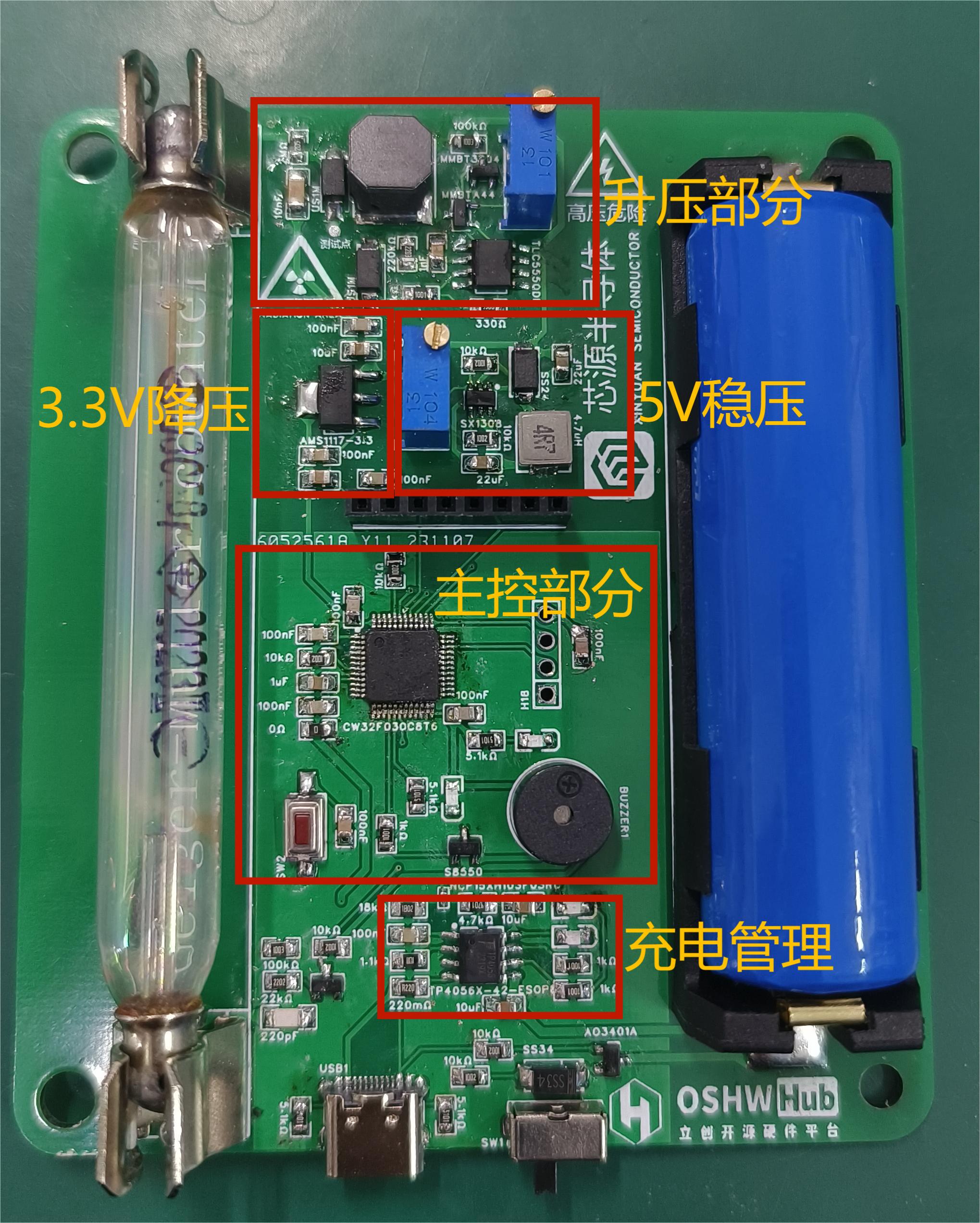
This project has two versions: 1.0 and 2.0. Version 1.0 is for debugging a separate circuit, suitable for the initial stage of the project, while version 2.0 integrates the entire system.
2. Open Source License:
CC BY-SA 4.0
3. Project Functionality
: Provides audio and visual alerts based on radiation levels
. Can be charged via a mobile phone charger, eliminating the need for frequent battery replacements and protecting the environment.
Features a rich UI interface, allowing users to intuitively view current radiation parameters .
When a TYPE-C interface is inserted, the power supply circuit automatically switches. The entire circuit is powered by the charger and simultaneously charges the battery.
4. Project Schedule:
Project construction began on September 1, 2023, along with the construction of the simulation circuit.
September 4, 2023: PCB design completed, but abandoned due to soldering and replication difficulties.
September 17, 2023: PCB design completed. This PCB layout is modular for easier debugging.
October 10, 2023: PCB debugging successful; V2.0 design begins.
November 7, 2023: V2.0 design completed; programming and casing printing begin. November 17
, 2023: Completed.
5. Design Principles
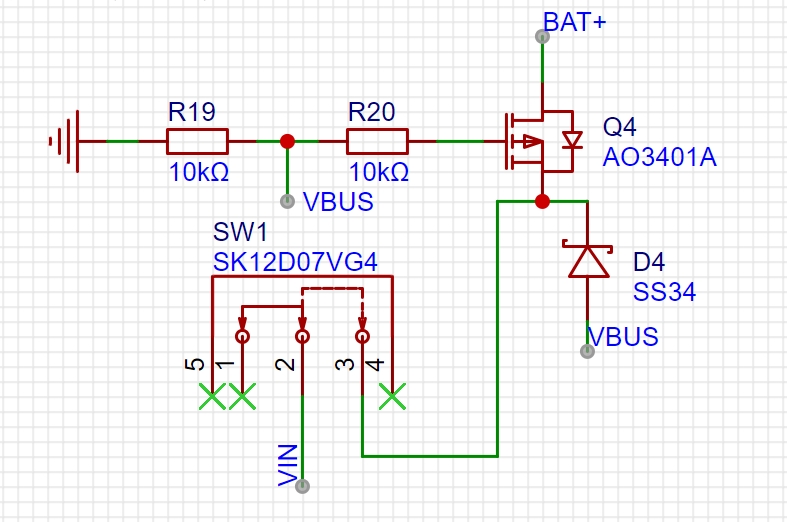
: 1. A switching circuit is implemented using a MOSFET. When an external power supply is available, the battery output is automatically cut off, allowing the external power supply to power the entire circuit and charge the battery simultaneously.
2. The TP4056X lithium battery charging chip is used to charge the battery. The charging circuit used in this project has temperature feedback; overheating automatically disconnects charging to prevent danger. Compared to the TP4056, the TP4056X has built-in reverse connection protection, making the external circuit simpler.

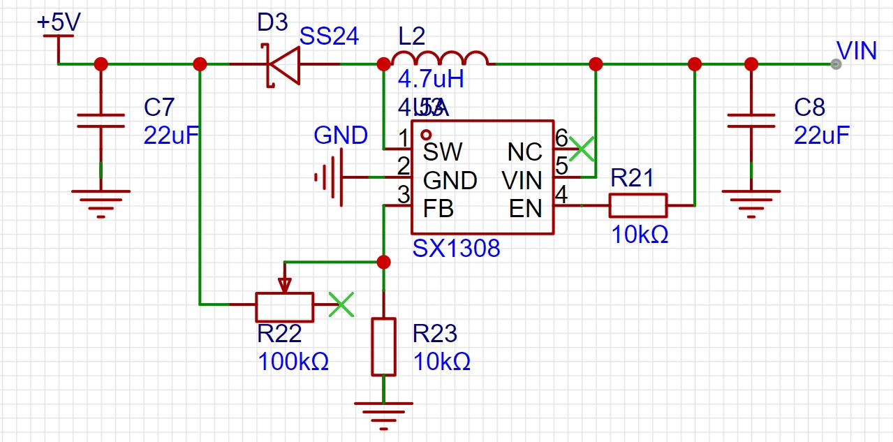
3. An SX1308 boost converter chip is used to boost the 4.2V lithium battery voltage to 5V, preventing malfunctions caused by low battery voltage. This design also stabilizes the Geiger transistor's operating voltage, avoiding counting anomalies due to low battery power.
4. A Boost converter circuit is used in conjunction with a TLC555 to achieve voltage boosting. The duty cycle of the timer is adjusted by changing the adjustable resistor, allowing for adjustable boost voltage.
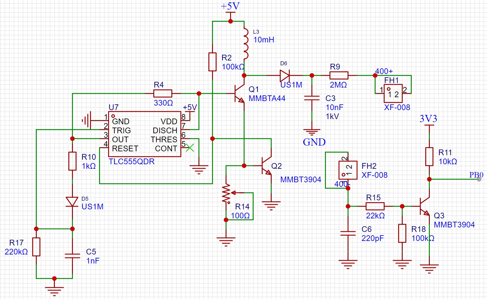
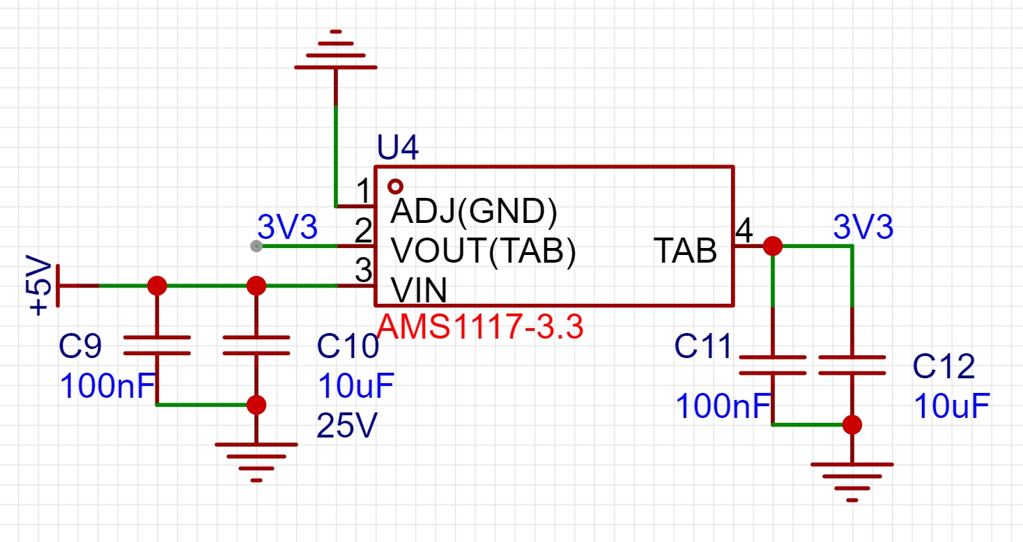
5. An AMS-117 3.3V LDO linear buck converter chip is used to step down the regulated 5V to 3.3V to power the microcontroller.
6. A 1.8-inch LCD TFT screen is used to display the collected data.
7. Counting is achieved using a transistor. When a radiation source is present, the emitted rays pass through the Geiger transistor and are ionized, generating a pulse signal. The transistor then conducts, and the microcontroller's GPIO port is configured as a pull-up input. When the transistor is on, the GPIO port goes low, triggering an interrupt and completing one count.
8. Numerical conversion is achieved by configuring a timer to implement 1-second timing, i.e., reading the GPIO interrupt count every 1 second. The main loop checks if the timer flag has changed to read data every 1 second and convert it into the corresponding radiation value. This flag-based method avoids executing too many functions within the timer interrupt, which could cause program blocking.
9. The buzzer alarm sound frequency varies with the radiation value. I used hardcoding this part of the code, dividing it into multiple levels, each corresponding to a different frequency. Frequency changes are achieved through delays. However, traditional buzzer alarms mostly use delay functions, which can block normal program operation. Therefore, I used a 1ms timer to implement the delay within the timer, i.e., checking the given time duration, and then using an if statement within the interrupt to check if the time has elapsed. This part is a bit convoluted and requires multiple readings.
10. Screen refresh uses flags, as mentioned in point 9, with different flags corresponding to different levels, thus determining whether the screen background color needs to be refreshed.
6. Software Description:
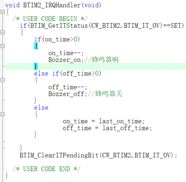
This part of the code executes within the 1ms timer interrupt. `on_time` and `off_time` are the buzzer's on and off times. For example, setting `on_time` to 100 means the buzzer will sound for 100ms.
`last_on_time` and `last_off_time` are used to save the last set time, allowing the buzzer to sound repeatedly; otherwise, it would only sound after each value is set.

This part of the code is the core of the entire program. It checks the value of `FLAG` to determine if the 1-second timer has ended, and then performs the numerical conversion.
`color_flag` is used to determine if the background needs to be changed. The conditional statement within the `case` statement is to avoid constantly refreshing the background, as this would cause screen flickering.

This section showcases the UI design
and presents a future
vision
. If possible, battery voltage detection will be added, and the circuit design will be optimized for a smaller size. However, due to the high price of Geiger tubes, this may be shelved. Interested parties can follow this project.
Design Notes:
Pay attention to safety during soldering.
After soldering, adjust the 5V regulator circuit first to 5V before adjusting to 400V.
Do not connect the Geiger tube to the circuit during 400V boost adjustment to avoid damage due to excessive voltage (each tube is expensive, and it's painful to see it damaged).
When adjusting the voltage, use a multimeter to measure and adjust simultaneously. The multimeter range must be selected correctly.
The multimeter must be error-free when measuring high voltage. I personally encountered this situation before, where low voltage measurements were accurate, but high voltage measurements were inaccurate.
All circuits in this project have been tested by me and can be ordered directly.
Since the inductors used in the 5V to 400V circuit are currently expensive on Taobao, a corresponding I-type inductor can be used as a substitute.
Demonstration Video
[Open Source!!] [A Nuclear Radiation Detector with a Tiny Bit of Danger] https://www.bilibili.com/video/BV1iv411c7yZ?vd_source=8aba9b5c4b883e036e8f6340b7370c04
Project Attachments: Entries participating in the event must upload the relevant program attachments to an open-source platform or their personal code storage cloud. The maximum upload size for attachments is 50MB (please do not upload to the LCSC workspace, as there are limitations).
Geiger counter -- CW32.zip
BOM_Geiger_v2.0_V2.0_2023-11-20.xlsx
Gerber_V2.0_2023-11-20.zip
Case .DWG
PDF_Nuclear Radiation Detector_Geiger-Müller Counter.zip
Altium_Nuclear Radiation Detector_Geiger-Müller Counter.zip
PADS_Nuclear Radiation Detector_Geiger-Müller Counter.zip
BOM_Nuclear Radiation Detector_Geiger-Müller Counter.xlsx
90966
DIY Mini 720P Projector
A very small LCOS projector with a native resolution of 720p. Supports HDMI, RGB888, and MIPI-DSI inputs.
This project introduces
a small projector optical engine driver board. It includes two boards:
a four-layer board, an OVP2200 screen driver board using the OVP0921 driver IC, supporting RGB and MIPI-CSI input, but requiring prior configuration of relevant parameters and initialization code via I2C;
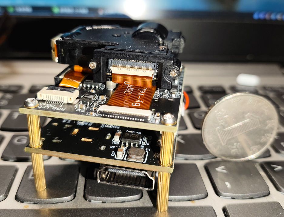
and a two-layer board, an RTD2662-based HDMI input to RGB888 driver board, supporting 5-24V DC input, a built-in I2S DAC, and an added power amplifier for direct audio output. The physical assembly
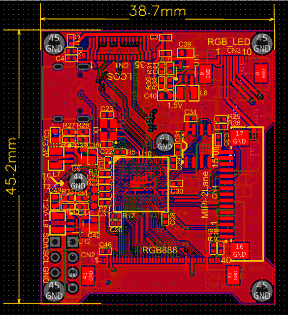

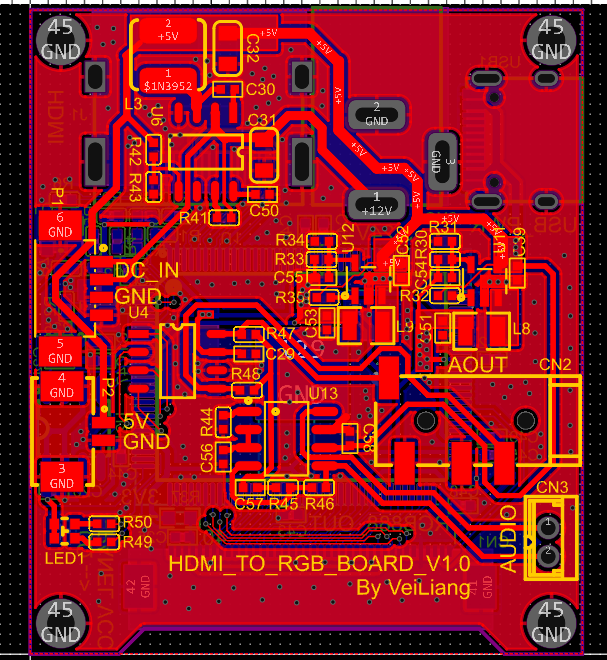

details are as follows:
the optical engine, with a resolution of 1280x720, was found on Xianyu (a Chinese online marketplace). It was originally from a projector, likely a cancelled order. While the resolution is high, the driver is complex, requiring a dedicated driver IC. The LCOS chip is OVP2200, and the driver IC is OVP0921. This chip is somewhat expensive, but JLCPCB currently has some in stock. I quickly assembled a driver board and powered up the screen. The driver board inputs are a standard 40-pin RGB888 interface and a Raspberry Pi MIPI-CSI interface. The OVP0921 has a built-in microcontroller, which can be started and run in two ways: one is via an external SPI flash chip, and the other is via an I2C interface after uploading the firmware sequence. Currently, it seems that firmware code is required for other register configurations to take effect. Therefore, the author placed a PY32F002A on the driver board to dynamically initialize the OVP0921 based on user selection.
For detailed driver information, please see the sharing link: https://whycan.com/t_10203.html.
Next are actual photos and
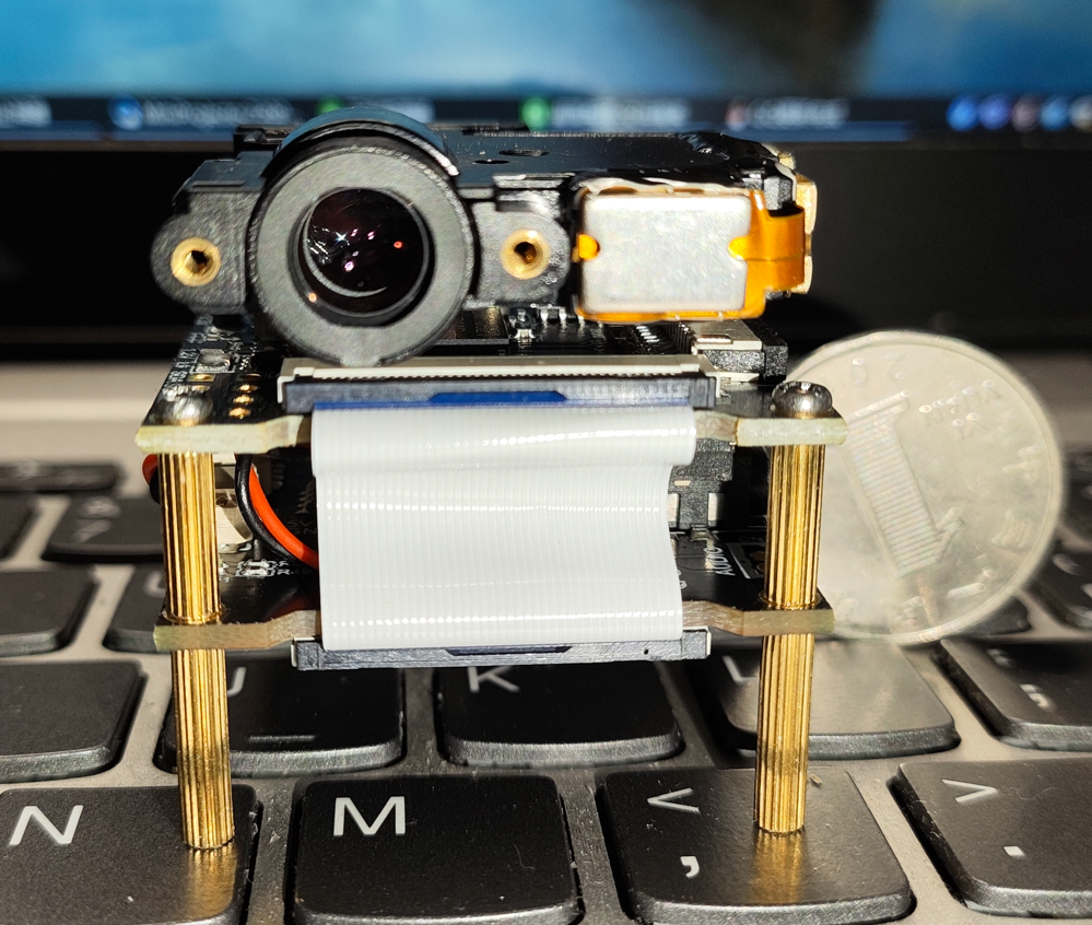

videos: https://www.bilibili.com/video/BV1Lr42187pE/?spm_id_from=333.999.0.0
VID_20231116_014013.mp4
PDF_DIY Mini 720P Projector.zip
Altium_DIY Mini 720P Projector.zip
PADS_DIY Mini 720P Projector.zip
PDF_DIY Mini 720P Projector.zip
Altium_DIY Mini 720P Projector.zip
PADS_DIY Mini 720P Projector.zip
90967
IP5389-based portable power bank
Based on Ingenic IP5389 AACC 100W power bank
Note:
This project is quite difficult to produce and is not recommended for replication!
This project is quite difficult to produce and is not recommended for replication!
This project is quite difficult to produce and is not recommended for replication!
This project uses the IP5389 AACC version! The
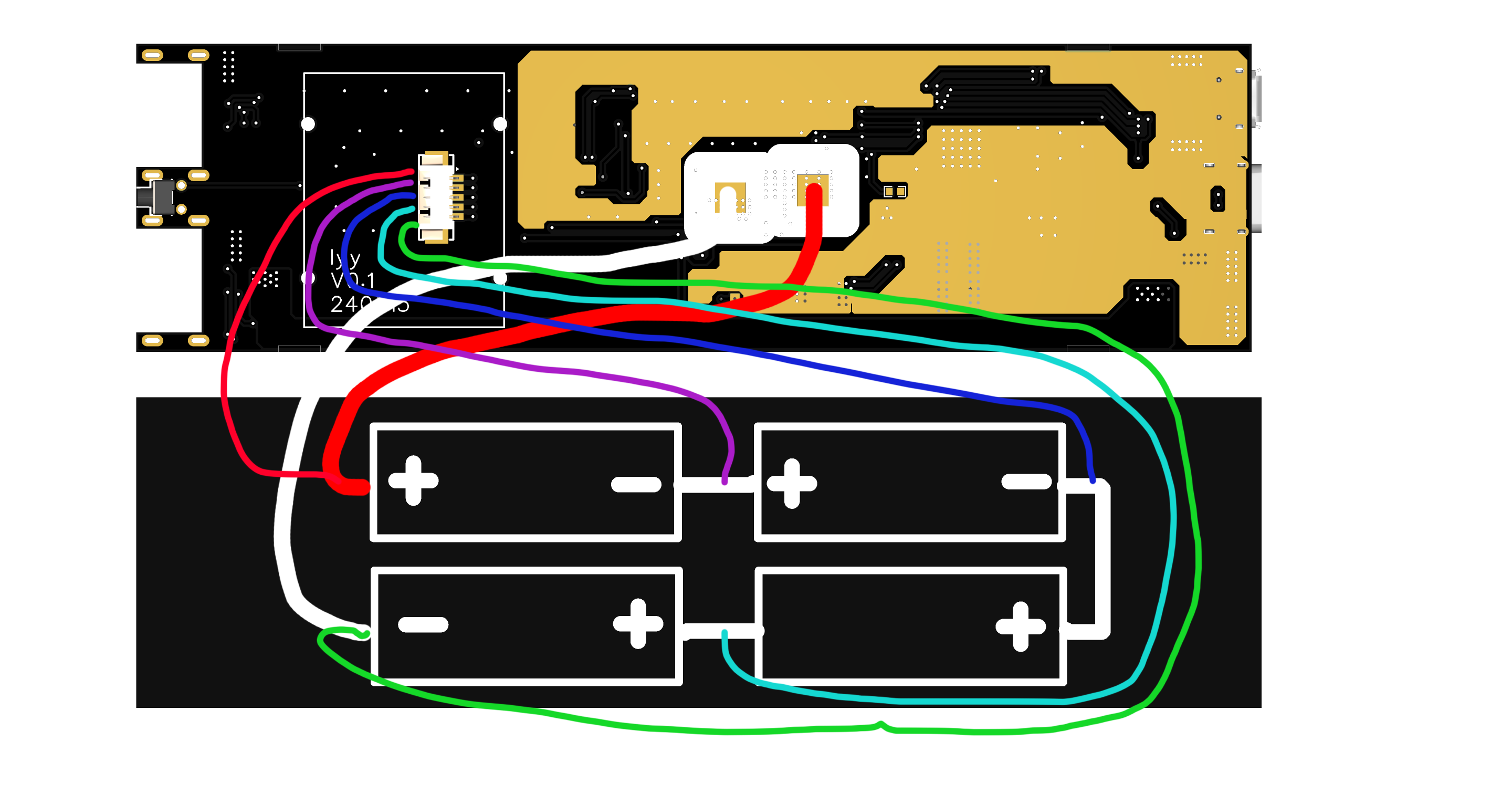
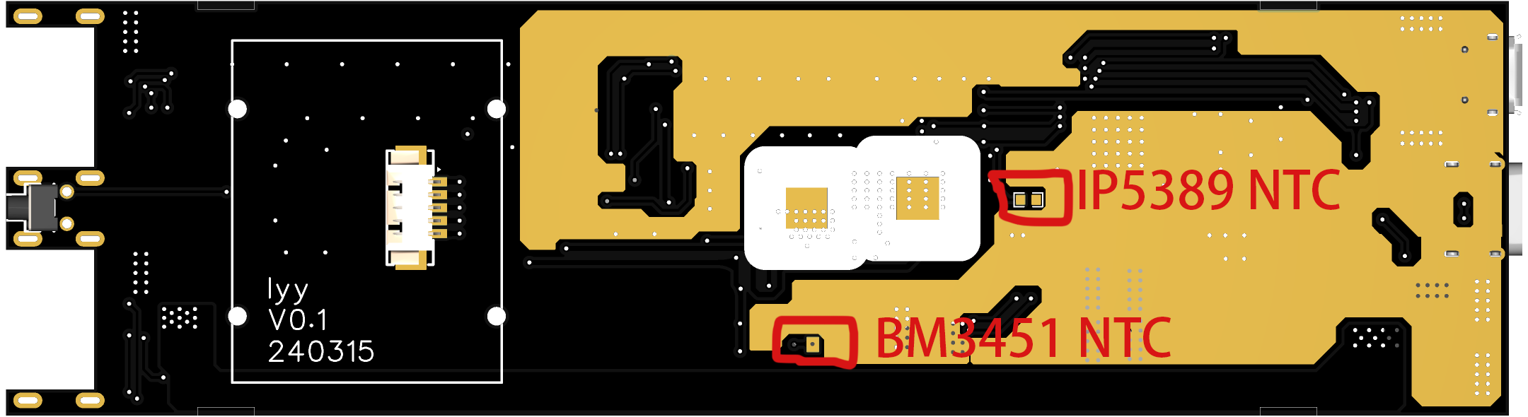
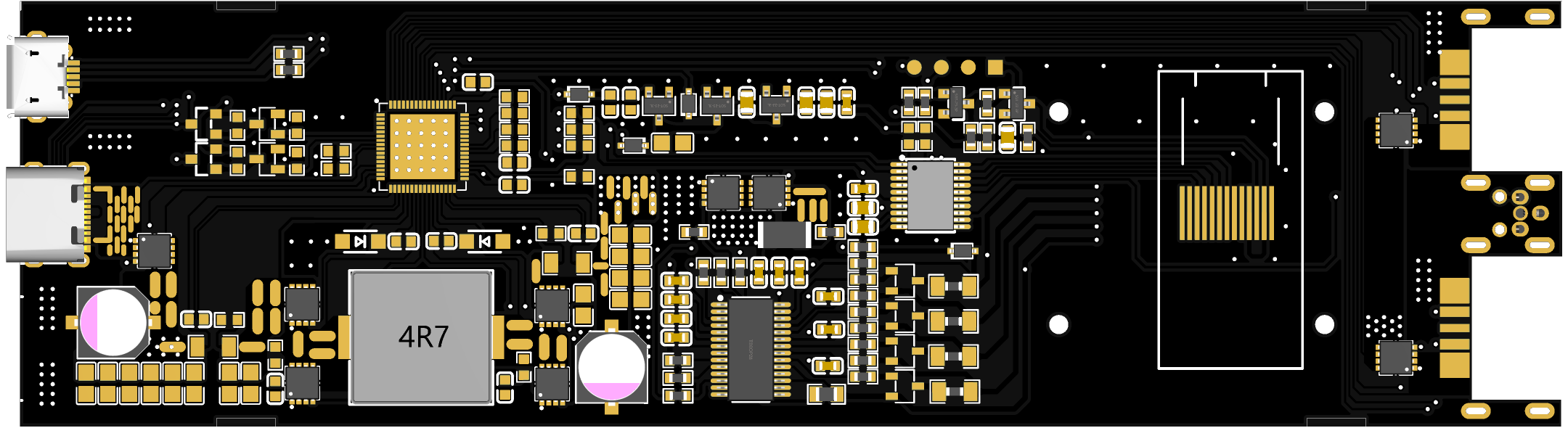
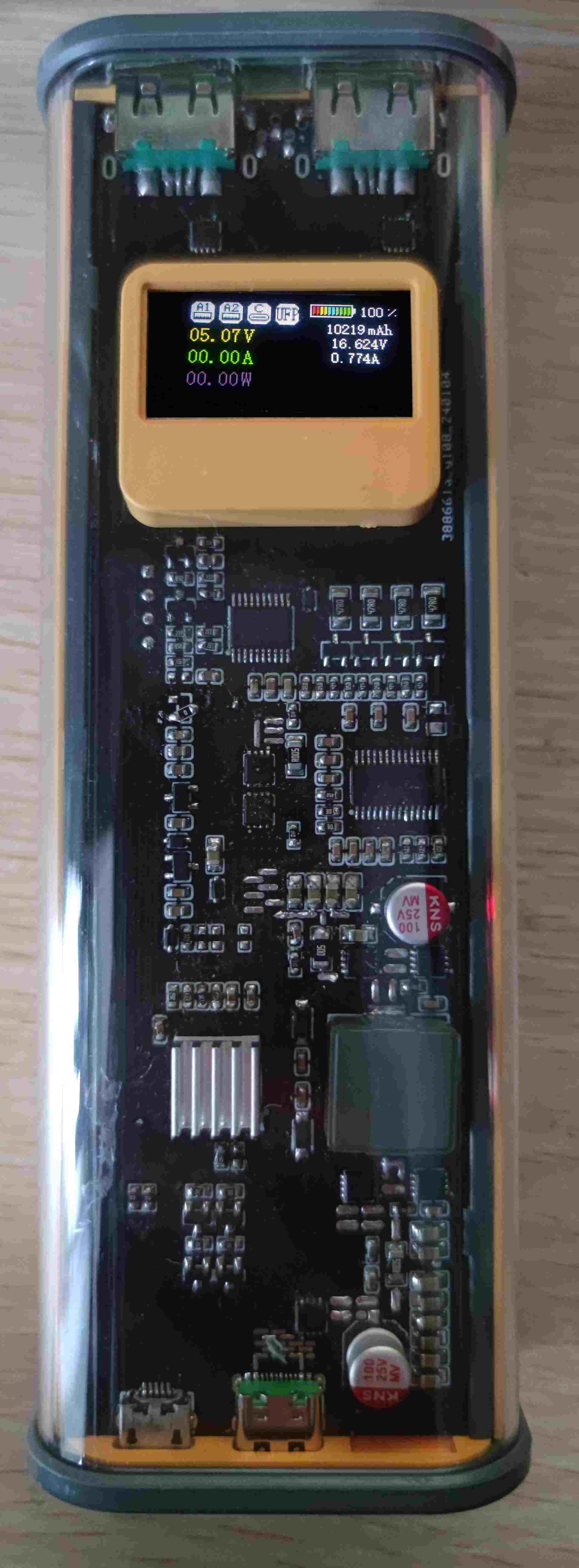
PCB length is 145MM, and free prototyping is not available! This project is based on the Ingenic IP5389 AACC buck-boost power management SOC chip + STC8H8K64U microcontroller + BM3451 battery protection chip. This project shared is version V01, unverified. (Some may ask why a verified project wasn't shared. That's because the verified project had some minor issues, and after subsequent wire-based verification, the changes were made directly to the original project without a backup. The original project had two issues: 1. Microcontroller I/O port allocation problem. 2. The USB-A port pad position was slightly offset, requiring pin bending during soldering.) 1. The original project has been verified to have normal charging and discharging functions (60W charging, 100W discharging (Note: the MOSFET and inductor generate a lot of heat during 100W discharging; they can be replaced with MOSFETs and inductors with lower internal resistance)). 2. The power consumption of the microcontroller + display in sleep mode is around 60uA, and 30mA during normal operation. The overall standby power consumption was not measured. 3. The discharge resistor generates a lot of heat when the BM3451 is in balanced mode; a more suitable resistor value can be replaced. (This project uses 47R) 4. The IP5389 AACC version supports 2A and 2C, but this project only uses 1C and 2A. The Micro-B port next to the C port is used for programming. 5. Because the IP5389 measures current through the internal resistance of the MOSFET, the values read are inaccurate. The data displayed on the screen is for reference only. 6. The battery voltage, battery current, and battery capacity displayed on the screen are inaccurate. Furthermore, when the battery current is greater than 6A, the data read is incorrect, displaying 1A. This issue needs to be fixed. 7. A short press of the button powers off, and a long press for 1-1.5 seconds powers on. 8. Battery balancing line connection method is shown in the figure below: 9. NTC thermistor This project has two NTC thermistors, one is BM3451 for detecting battery temperature, and the other is IP5389 for detecting battery temperature, as shown in the figure below: 3D model showing PCB board thickness 1.0 or 1.2MM Physical demonstration Programming 1. Select 30MHZ frequency 2. Press and hold the button on the board, and then plug in the data cable. At this time, the STC-USB Writer (HID1) serial port will be displayed (if the serial port is not displayed, repeat this step), as shown in the figure below: Note: The board has reserved programming pads, which can be connected to a USB to TTL module to program the firmware, or the firmware can be downloaded using the method in step 2 (square pad 3.3V, adjacent round pads are GND-RXD-TXD) Note: The firmware is not yet complete and is not open source at present, but may be open source in the future.

IP5389_I2C_AACC Power Bank V0.hex
PDF_IP5389-based portable power bank.zip
Altium_IP5389-based portable power bank.zip
PADS_IP5389-based portable power bank.zip
Altium_IP5389-based portable power bank.zip
PADS_IP5389-based portable power bank.zip
BOM_IP5389-based portable power bank.xlsx
90968
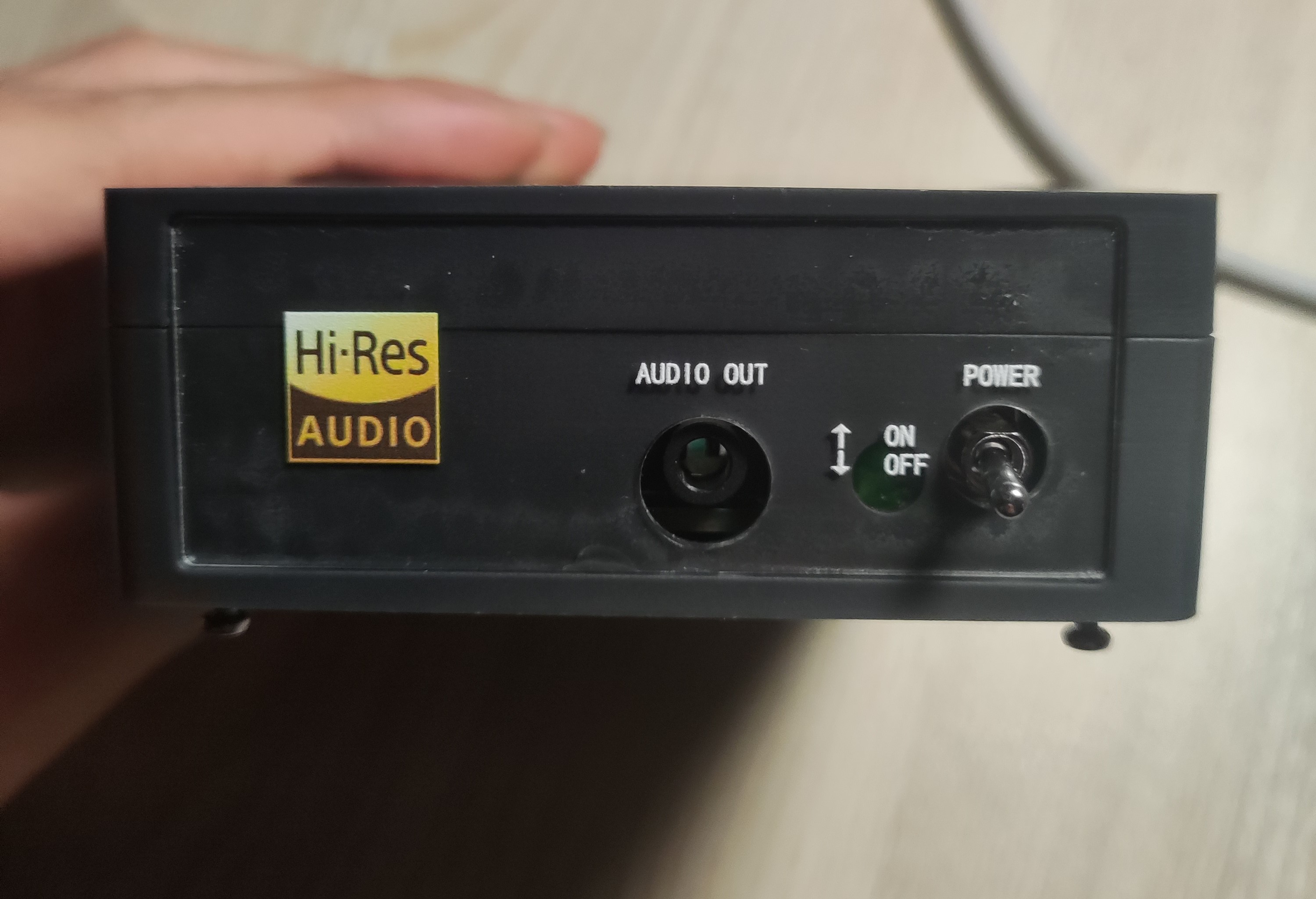
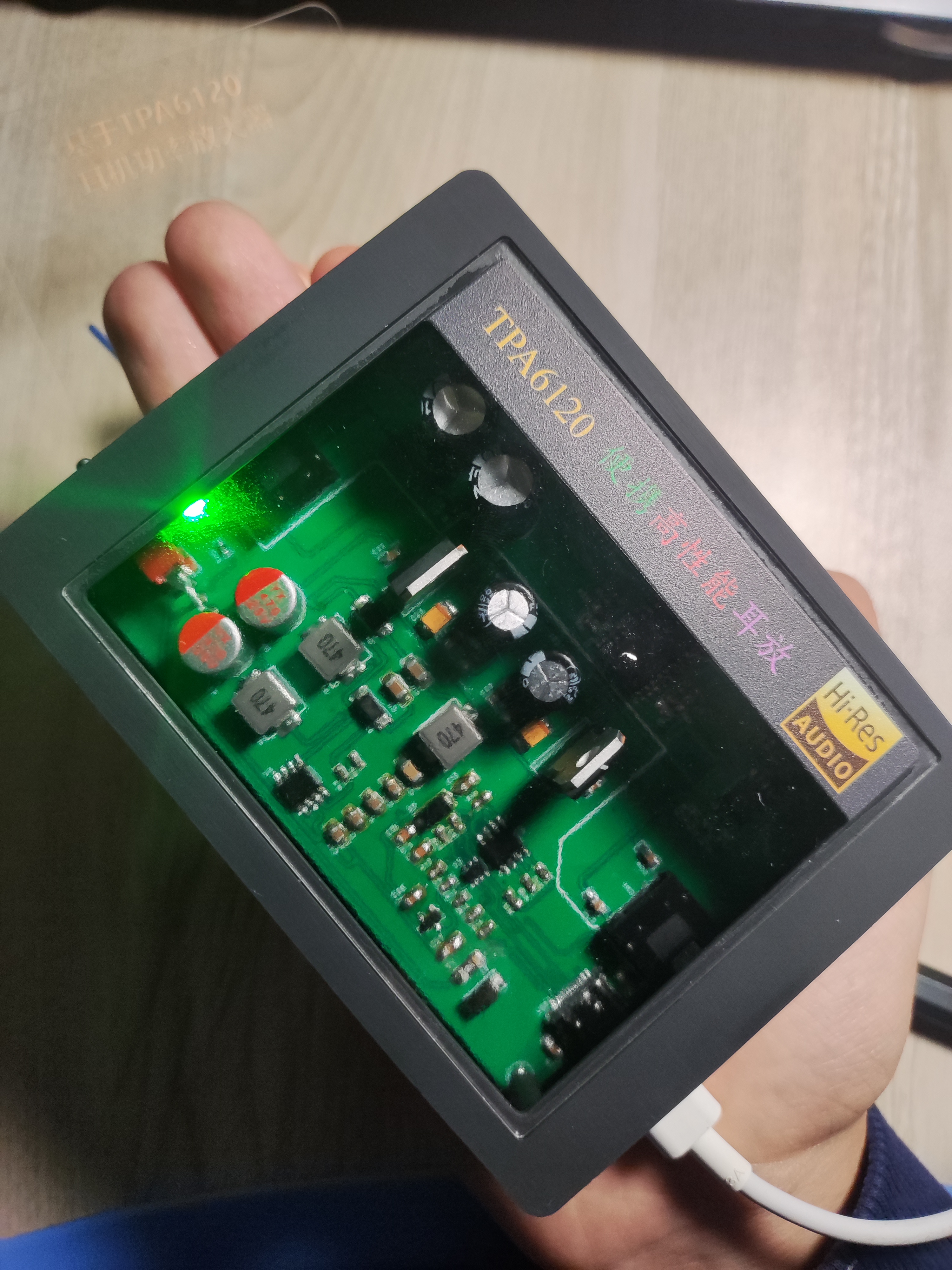
A brand new portable high-performance headphone amplifier based on the TPA6120 | TPA6120A2 | Headphone power amplifier
The TPA6120 is designed to improve headphone sound quality at a low cost, capable of driving headphones with an internal impedance of up to 600 ohms, and features 3.5mm input and output. It supports Type-C PD/QC power supply, and is compact, highly portable, feature-rich, and cost-effective.
I. Project Description
A headphone amplifier, or headphone power amplifier, can drive headphones with higher internal impedance and enhance the music listening experience. However, commercially available headphone amplifiers are several times more expensive than their cost price, lack USB-C input, and make it impossible to design the internal circuitry yourself. Therefore, this project aims to create a powerful, low-cost portable headphone amplifier.
>>>Click here to watch the demo video<<<
II. Open Source License
GPL 3.0
III. Project Features
[x] Can drive headphones with a maximum impedance of 600 ohms, even low-sensitivity headphones;
[x] Compact size, easy to carry;
[x] Powered by USB Type-C, supports PD/QC protocols;
[x] Carefully designed circuitry ensures minimal interference for a truly HI-FI music experience.
IV. Project Attributes
This project is being publicly released for the first time and is my original work. This project has not won any awards in other competitions.
V. Project Schedule
February 17, 2024:
Project created, schematic drawing started . February
18 , 2024:
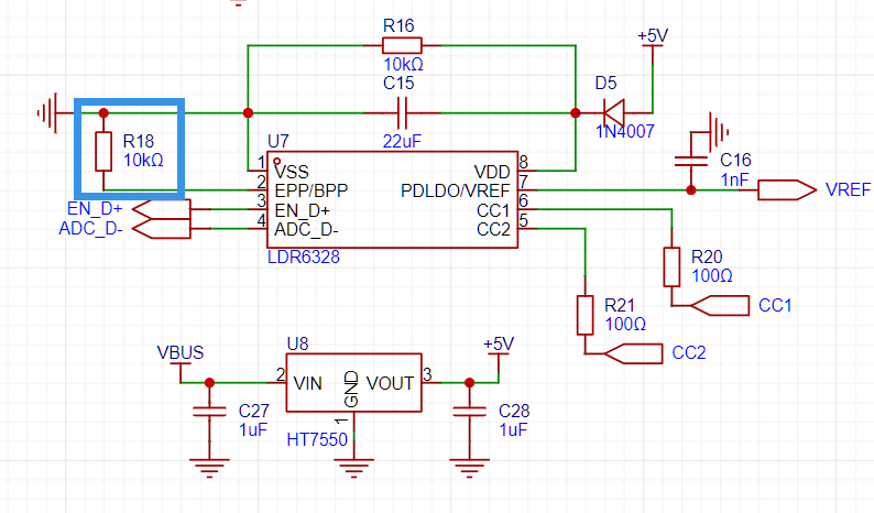
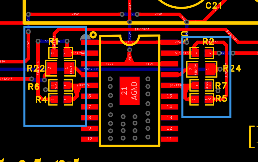
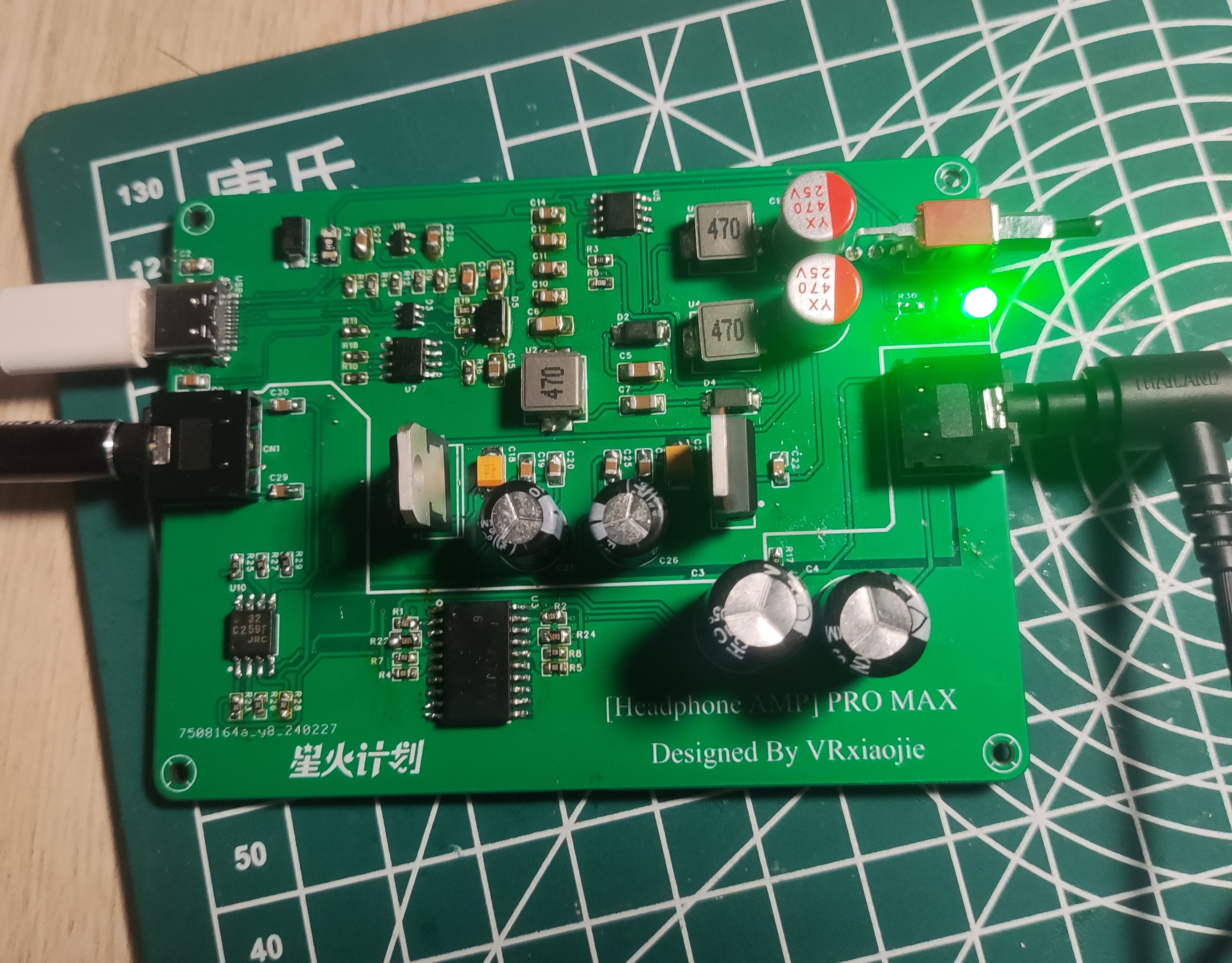
Schematic drawing completed. February 19 , 2024: PCB design started . February 27, 2024: Design completed, PCB layout optimized. February 29, 2024 : Soldering started. March 2, 2024: Physical testing completed, functions normally; casing and panel design started. March 5, 2024: Casing and panel design completed . March 8, 2024: Casing and panel installation completed; project completed! VI. Design Principles 1. TPA6120A2 Audio Power Amplifier: This is the core of the project. According to the datasheet, ±15V power supply performs better than ±5V; therefore, ±15V power is used. 2. NJM5532 I/V Conversion 3. LDR6328 PD/QC Decoy Input: Pin 2 of the LDR6328 is connected to a pull-down resistor, indicating that the adapter is decoyed to try 12V, 9V, and 5V outputs sequentially, prioritizing PD and then QC. 4. The voltage is converted to ±17.5V by a SPEIC circuit, and then regulated to ±15V by an LDO to provide the operating voltage for the op-amp. VII. Precautions: Note that the resistor next to the TPA6120 should be placed close to the chip pins (within the blue box). Recommended power-on and wire insertion order: First connect the audio output device (phone/computer, etc.) to the AUDIO IN interface, then connect the AUDIO OUT interface to the headphones, then plug in the Type-C power supply, turn on the power switch, and finally put on the headphones. This is to prevent the "pop" sound caused by power-on from damaging hearing. If you have a solution, please leave a comment! Thank you! It is best to use a power bank/phone charger that supports 9V/12V voltage and QC/PD protocol. Testing with a computer's USB 3.0 interface showed a voltage of around 5V, with very noticeable background noise, which is suspected to be due to insufficient power supply from the computer's USB interface. VIII. Project Reference Circuit: Refer to the designs of the following two experts, thank you. The TPA6120 desktop headphone amplifier and TPA6120A2 headphone amplifier also referenced the datasheets of the chips used: LDR6238, XL6007E1, and TPA6120A2. IX. Physical Demonstration : During operation, the bare board appears as a 3D-printed shell with a transparent top panel. The front and rear panels are shown. The headphones used for testing were Sony WH-1000XM4, and the soundstage was found to be wider and the details richer. X. Notes: 10.1 Originally, I wanted to make a portable headphone amplifier with a Bluetooth + battery combination. However, halfway through, I realized that adding more batteries significantly reduced its portability (increasing its size) and required frequent charging (the measured power was approximately 1.5W; assuming a 5000mAh lithium battery, it theoretically only lasts about ten hours). Therefore, I changed my approach and made a smaller headphone amplifier that can be used on a desktop or carried around. It uses Type-C power and is powered by a power bank when out and about, or a mobile phone charger. Additionally, "portable" refers to its small size (only palm-sized) and light weight. This is my second open-source project ( 10.2 ). It's been a month and a half since I first encountered JLCPCB, so there are bound to be shortcomings. I hope to learn from and exchange ideas with experienced developers in the comments section. This project participates in the Spark Program. If you think it's good, please like and bookmark it, and leave your opinions and suggestions in the comments section. Welcome to replicate and improve this design! Possible features to be added after 10.3 (version 2.0): [ ] Type-C digital input, built-in DAC decoding


Introductory video.mp4
PDF_New Portable High-Performance Headphone Amplifier Based on TPA6120_TPA6120A2_Headphone Power Amplifier.zip
Altium_New Portable High-Performance Headphone Amplifier Based on TPA6120_TPA6120A2_Headphone Power Amplifier.zip
PADS_New Portable High-Performance Headphone Amplifier Based on TPA6120_TPA6120A2_Headphone Power Amplifier.zip
BOM_New Portable High-Performance Headphone Amplifier Based on TPA6120_TPA6120A2_Headphone Power Amplifier.xlsx
90969
electronic


 京公网安备 11010802033920号

 RJU6054WDPK-M0


