Update Log
March 8, 2024 (
First Release)
March 18, 2024:
1. Updated BOM (Bill of Materials) and simplified production steps;
2. Updated production video.
March 23, 2024:
Updated panel dimensions.
Precautions
: After completing the ECHO heating platform:
Activate
and set the power.
Clean the heating plate
and heat it at approximately 220℃ for 1 minute to oxidize the aluminum substrate surface.
After completing the above steps, the heating plate will have very little solder adhesion.
The optimal operating temperature is 100-240℃, and short-term operation at 300℃ is fine. Due to the insulation material of the aluminum substrate, excessively high temperatures will produce harmful gases and cause irreversible damage!
Open Source License
: This project uses the CC-BY-NC-SA 3.0 open source license, i.e., Creative Commons Attribution-NonCommercial-ShareAlike.
CC: Creative Commons Attribution
-Attribution. You must give appropriate attribution, provide a link to this license, and indicate whether modifications were made (to the original work).
SA: Share Alike. If you remix, transform, or build upon this work, you must share and distribute your contributions under the same license as the original.
NC: Non-Commercial. You may not use this work for commercial purposes.
Features:
The ECHO heating platform uses an STC8H8K64U microcontroller with built-in USB functionality, employing a CH224K decoy chip, supporting PD3.0/2.0. The screen is a 0.91-inch OLED display at a 45° angle. The heating plate uses an aluminum-based heating plate (available in two versions, H50/H34). The casing is 3D printed. The controller and heating plate are detachable for easy selection and modification.
The domestically produced STC8H8K64U chip
features built-in USB hardware, supports software updates
, a Type-C power interface supporting PD3.0/2.0 protocols
, a 0.91-inch IIC OLED screen with three color options
, a 45° angled display for easier data viewing
, a front-mounted dial switch for convenient one-handed operation,
three operating modes: constant temperature mode, curve mode, and reflux mode
, a plug-in design for the controller and heating platform supporting different heating plate sizes
, and a photopolymer 3D printing option for JLCPCB 3D printing, allowing for selection of different colors and materials
for the panel.
The ECHO control board is designed as a double-layer board, showcasing JLCPCB's newly upgraded immersion gold process.
Operation instructions:
The buttons have three positions: up, middle, and down.
The up and down buttons default to an increase/decrease principle.
The middle button is the function button.
1) On the main interface, single-click the function button to turn heating on/off; in constant temperature mode, double-click the function button to switch between current, power, and internal resistance displays.
2) On the main interface, long-press the function button to enter the settings menu.
3) In the settings menu, you can select 5 settings items (PID, Parameters, Mode, Power, and Return) by clicking the up and down buttons.
4) In the settings menu, click the function button to enter the corresponding first-level menu.
5) In the first-level menu, click the function button, select the item to be adjusted, and adjust the corresponding data using the up/down buttons. Click the function button again to return to the first-level menu.
6) In the first-level menu, press and hold the function button or the return button to return to the settings menu. Press and hold the function button or the return button again to return to the main interface.
The
ECHO34 requires printing four PCB files: ECHO-Control Board, ECHO-Cover, ECHO-J34, and ECHO-G34.

Figure 1. PCBs required for ECHO34. The
ECHO50 requires printing four PCB files: ECHO-Control Board, ECHO-Cover, ECHO-J50, and ECHO-G50.
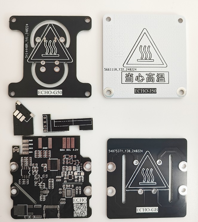
Figure 2. PCBs required for ECHO50.
ECHO-J34 and ECHO-G34 are combined to form the H34 heater.
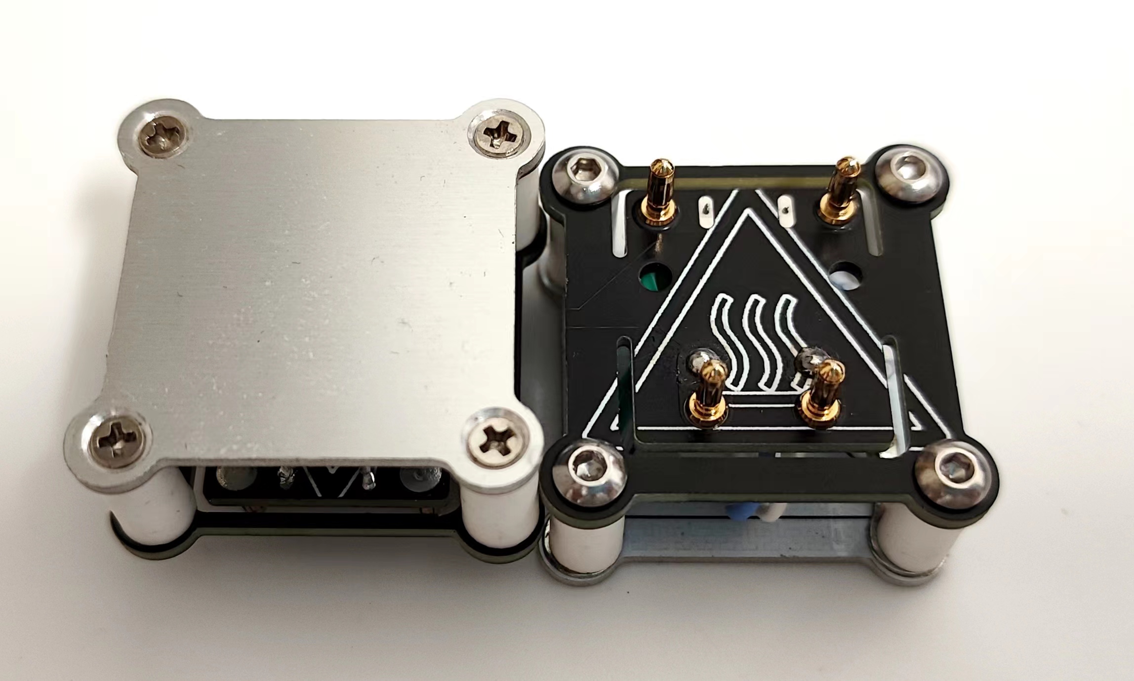
Figure 3. The H34 heater
ECHO-J50 and ECHO-G50 are combined to form the H50 heater.
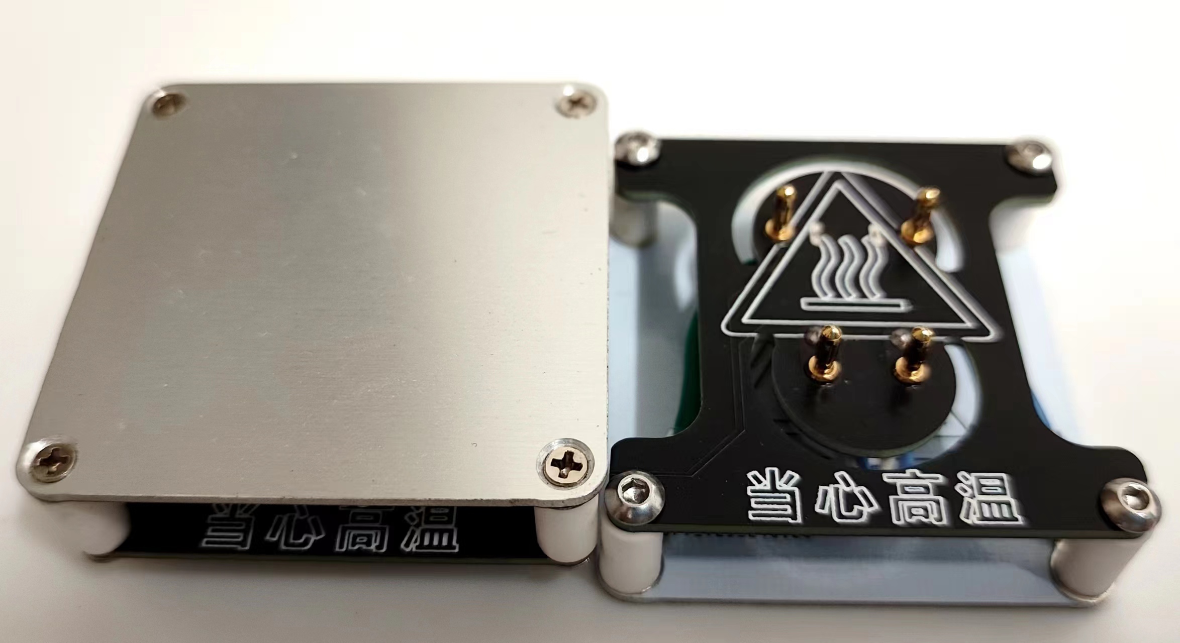
Figure 4. The H50 heater
ECHO-control board and ECHO-cover plate are combined to form the controller.

Figure 5. The controller
can be combined with the H34 heater/H50 heater to form ECHO34/ECHO50 respectively.

Figure 6. Left: ECHO50 Right: ECHO34
Welding and Assembly Tutorial
I. Welding Tutorial
Promotional Video: [Promotional Video] [ECHO-PD3.0 Heating Table]
ECHO-Control Board Welding
: [Part 1] [Control Board Welding] ECHO-Controller Assembly: [Part 2] [Controller Assembly]
ECHO-Heating Plate and Temperature Sensor Assembly: [Part 3] [Heating Plate and Temperature Sensor Assembly]
ECHO-Heater Assembly [Part 1]: [Part 4 (Part 1)] [Heater Assembly]
ECHO-Heater Assembly [Part 2]: [Part 4 (Part 2)] [Heater Assembly]
Temporarily completed.
II. Program Download Tutorial
Ensure correct welding before proceeding!!!
Open the STC-ISP software on your computer. Plug in the Type-C data cable
and press and hold the ECHO heating station function button. Quickly insert the Type-C port of the Type-C data cable into the Type-C port of the ECHO heating station .
If the soldering is completely correct, the STC-ISP software will display "STC-USB Writer (HID1)" (Figure 7).
If it is not recognized correctly, repeat steps b and c until it is recognized correctly

(Figure 7). After successful hardware recognition
, perform the following operation (Figure 8):
Chip model selection: STC8H8K64U
IRC Frequency: 33.1176MHz
EEPROM Size: 3K
Open Program File: PD-heating-stage.hex
Download

Figure 8. Software Configuration
After downloading the program, the screen should display correctly. If not, please check it yourself.
Welcome to join our group for discussion.
Communication methods
: Bilibili: a1298703610
QQ Group: 902453827
Acknowledgements
: Thanks to JLCPCB for the free PCB fabrication! Thanks to Along for providing the activation code!


 京公网安备 11010802033920号

 171-005-13P-.190-P3MH


