Note:
This project is quite difficult to produce and is not recommended for replication!
This project is quite difficult to produce and is not recommended for replication!
This project is quite difficult to produce and is not recommended for replication!
This project uses the IP5389 AACC version! The
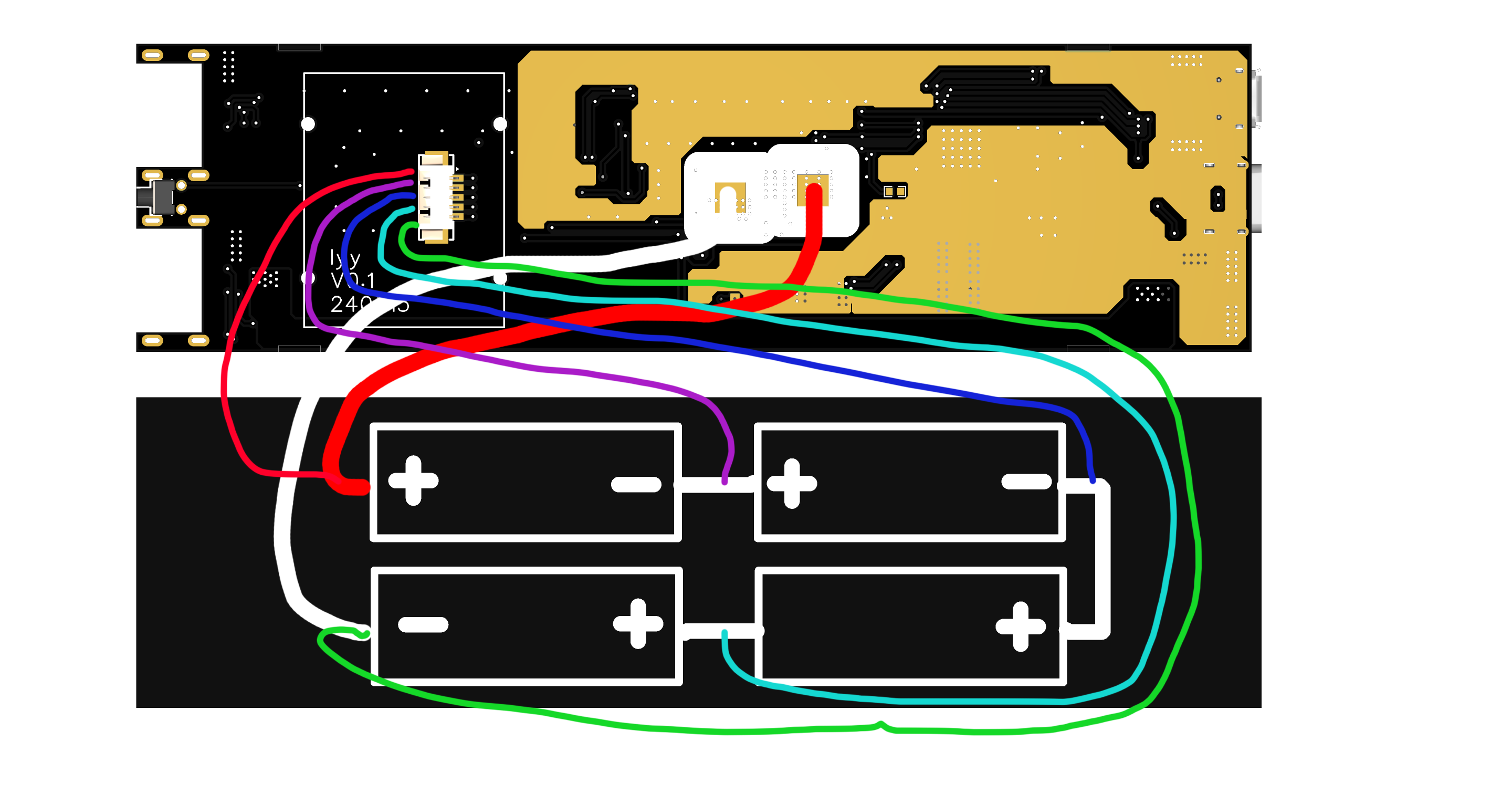
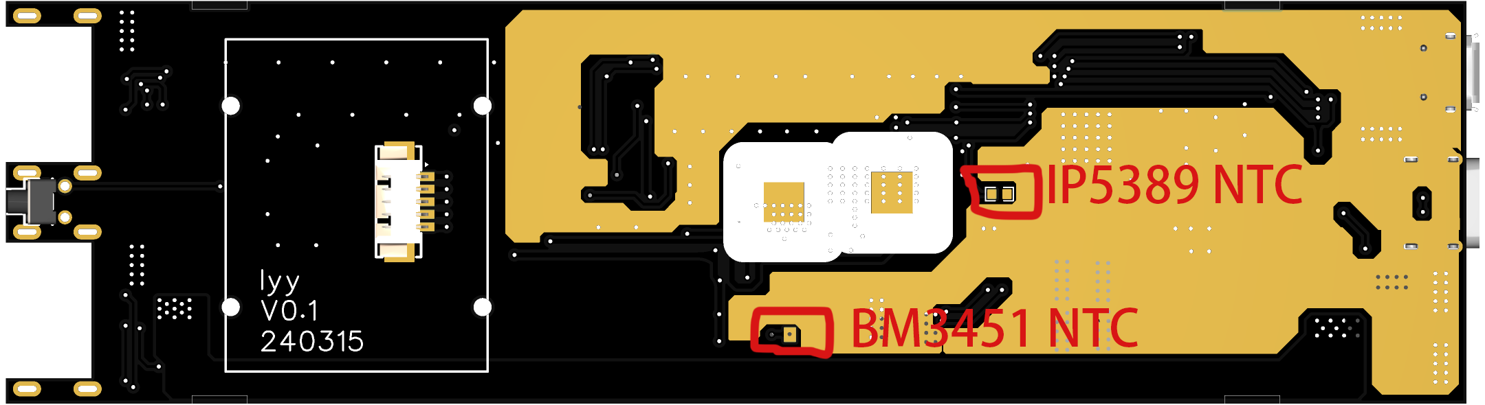
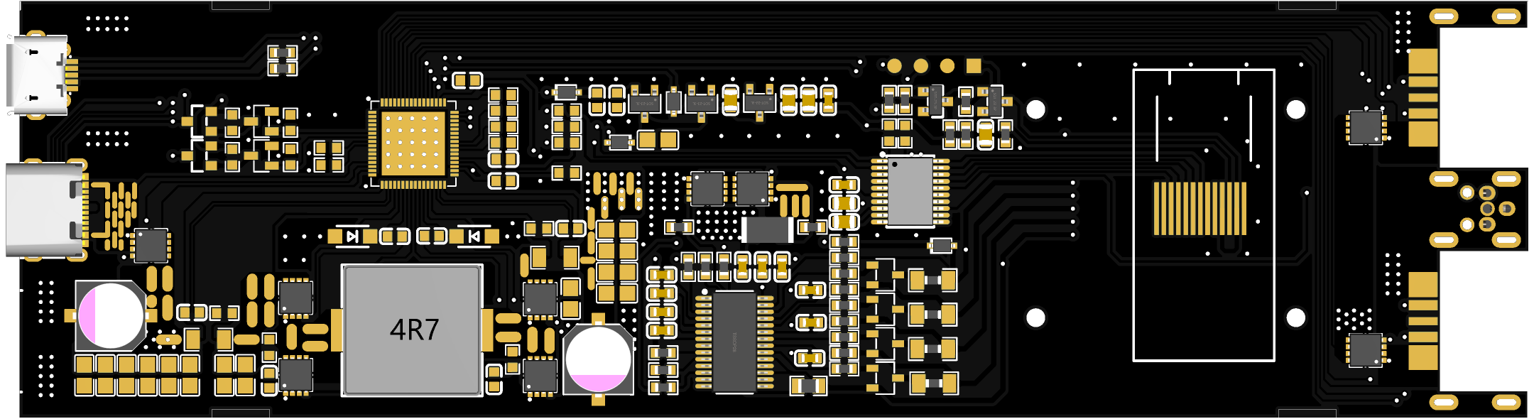
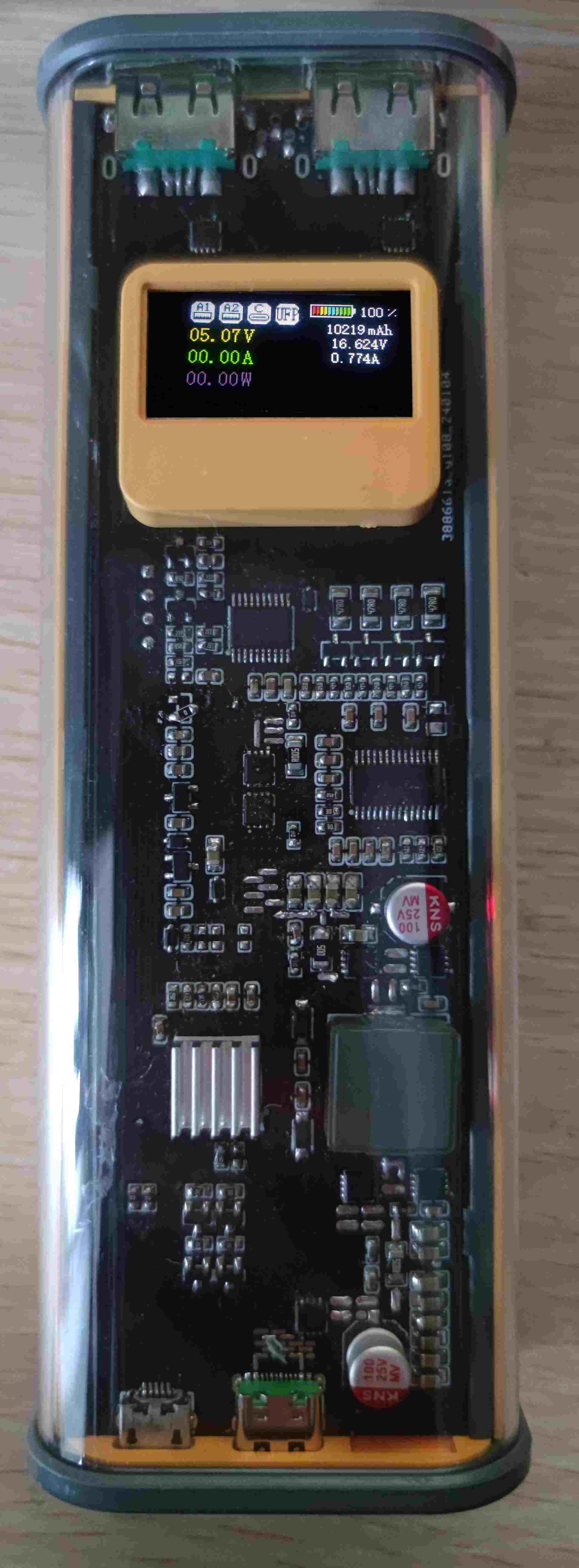
PCB length is 145MM, and free prototyping is not available! This project is based on the Ingenic IP5389 AACC buck-boost power management SOC chip + STC8H8K64U microcontroller + BM3451 battery protection chip. This project shared is version V01, unverified. (Some may ask why a verified project wasn't shared. That's because the verified project had some minor issues, and after subsequent wire-based verification, the changes were made directly to the original project without a backup. The original project had two issues: 1. Microcontroller I/O port allocation problem. 2. The USB-A port pad position was slightly offset, requiring pin bending during soldering.) 1. The original project has been verified to have normal charging and discharging functions (60W charging, 100W discharging (Note: the MOSFET and inductor generate a lot of heat during 100W discharging; they can be replaced with MOSFETs and inductors with lower internal resistance)). 2. The power consumption of the microcontroller + display in sleep mode is around 60uA, and 30mA during normal operation. The overall standby power consumption was not measured. 3. The discharge resistor generates a lot of heat when the BM3451 is in balanced mode; a more suitable resistor value can be replaced. (This project uses 47R) 4. The IP5389 AACC version supports 2A and 2C, but this project only uses 1C and 2A. The Micro-B port next to the C port is used for programming. 5. Because the IP5389 measures current through the internal resistance of the MOSFET, the values read are inaccurate. The data displayed on the screen is for reference only. 6. The battery voltage, battery current, and battery capacity displayed on the screen are inaccurate. Furthermore, when the battery current is greater than 6A, the data read is incorrect, displaying 1A. This issue needs to be fixed. 7. A short press of the button powers off, and a long press for 1-1.5 seconds powers on. 8. Battery balancing line connection method is shown in the figure below: 9. NTC thermistor This project has two NTC thermistors, one is BM3451 for detecting battery temperature, and the other is IP5389 for detecting battery temperature, as shown in the figure below: 3D model showing PCB board thickness 1.0 or 1.2MM Physical demonstration Programming 1. Select 30MHZ frequency 2. Press and hold the button on the board, and then plug in the data cable. At this time, the STC-USB Writer (HID1) serial port will be displayed (if the serial port is not displayed, repeat this step), as shown in the figure below: Note: The board has reserved programming pads, which can be connected to a USB to TTL module to program the firmware, or the firmware can be downloaded using the method in step 2 (square pad 3.3V, adjacent round pads are GND-RXD-TXD) Note: The firmware is not yet complete and is not open source at present, but may be open source in the future.


 京公网安备 11010802033920号

 4306T-102-1602DB


