A video introducing the solar-powered intelligent control greenhouse

is available on Bilibili: https://b23.tv/EkRvbg9.
For a more detailed introduction, please refer to the attached project report, demonstration video, and code.
Project Overview:
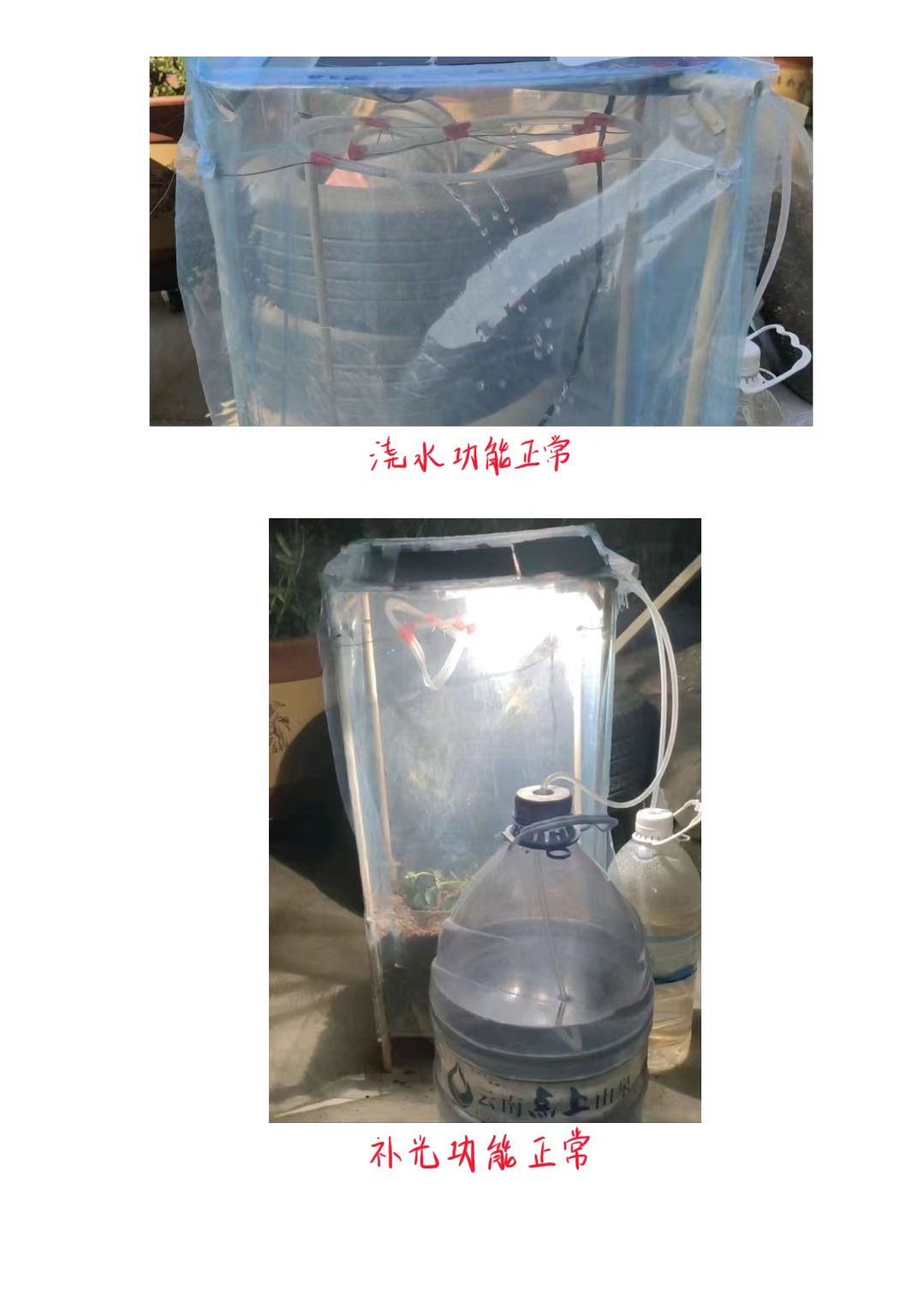
A small plant cultivation chamber powered by two solar panels, controlled by an STM32F103 microcontroller. It integrates a soil moisture sensor, a water pump, and supplemental lighting for automatic watering, fertilization, and appropriate supplemental lighting.
The system has a certain degree of offline stability, and the program uses an RTC clock-based wake-up method, allowing for long-term unattended operation.
It includes sensor normal operation detection, time anomaly detection, low battery detection, and corresponding backup systems for damaged sensors, time anomalies, coarse time correction, and low battery protection.
Project Design
Hardware Design:
I. Load Power Supply Circuit
1. Lithium Battery Solar Charging Module:
This module uses a TP4059 chip for lithium battery charging protection. Refer to its datasheet for specific circuit design.

2. 5V Boost Module:
This module uses an SX1308 chip for 3.7V to 5V conversion. A potentiometer is used for target voltage adjustment. The circuit uses a PMOS switch circuit, which can be enabled by a microcontroller to control the power detection module's on/off state.
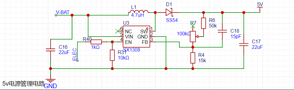
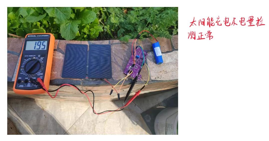
3. The battery power detection module
works simply by using two resistors to divide the battery voltage, halving it so the microcontroller's ADC can collect the entire battery voltage range. Software processing then yields the lithium battery voltage. By analyzing the relationship between power and voltage, a rough percentage of power can be determined.
A PMOS switch circuit is also used, allowing the microcontroller to control the module's on/off state. 4. The

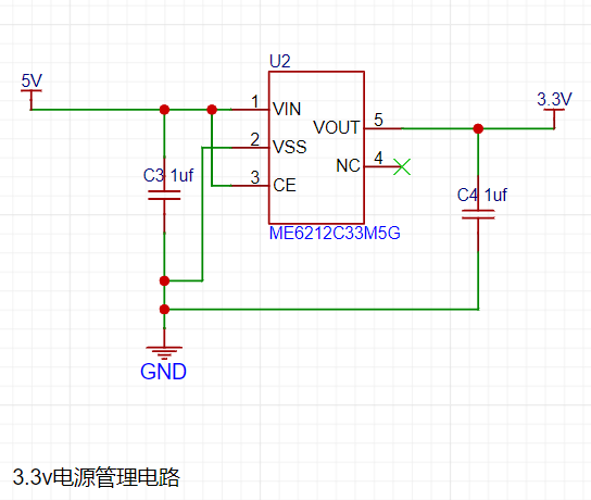
3.3V voltage regulator
module uses the ME6212C33M5G chip for 3.3V regulation, outputting a stable 3.3V voltage.
5. The switching circuit module
has two 5V switching circuits and one 3.3V switching circuit using a PMOS transistor, triggered by a low-level microcontroller pin. However, in actual use, the 5V switching circuit cannot be turned off by a high-level microcontroller pin due to the significant voltage difference between the microcontroller pin and 5V, resulting in the circuit remaining in a normally-on state.
Therefore, the code needs to be adapted. The solution is to use a floating pin input mode instead of a high-level pin. The load driven by the 5V switching circuit is two motors, so two Schottky diodes are added to prevent induced current.

II. System Control Circuit

A simple STM32F103C8T6 minimum system board can be completely replaced by a common minimum system board on the market.
Note: The microcontroller backup power module of the system control circuit has a design error and can be ignored. Ignoring this part will not affect the function of the control board, but using this part will make the board unusable.

I. Power Board Enable and Control Related Programs
1. The enable principle of the power detection function and the SX1308 chip 5V boost function
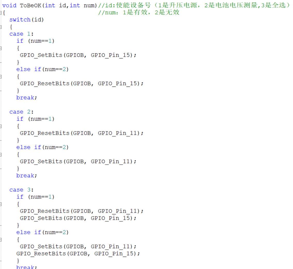
is very simple. The enable pin of the SX1308 chip is high-level to enable, and the enable pin of the power detection circuit is a PMOS switching circuit. Connecting it to a low level will enable it. It is a simple pin level control.
2. Switching Circuit Function Control Function The


3.3V switching circuit also uses pin level control. High level turns off and low level turns on. Because there is a pull-up resistor, the floating pin is also in the off state.
Let's focus on the 5V switching circuit. Initially, I used a push-pull output mode for enabling, but I found that neither a high nor low level could turn off the circuit. This is because the PMOS transistor's cutoff voltage is related to the input voltage, and the microcontroller's 3.3V high level is still considered "low" relative to the 5V input, thus keeping it in a conducting state. Therefore, a pull-up resistor is needed to provide sufficient cutoff voltage, essentially disconnecting the pin (setting it to a high-impedance state).
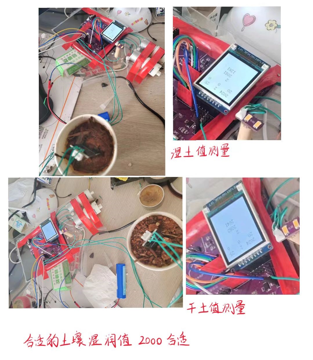
3. Both power detection and soil moisture acquisition
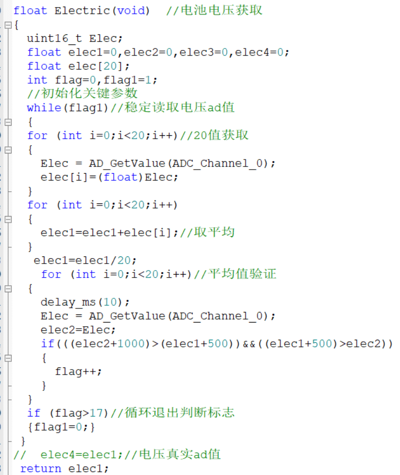
are simple ADC data acquisitions. I added some algorithms to reduce errors and data fluctuations.
4. Sleep Configuration:
Configure the power mode to standby mode, using an RTC alarm for timed wake-up. Pressing the reset button can also wake it up. The standby time is 3590 seconds, approximately one hour. Less than one hour allows for more stable timing tasks.


5. Sensor Fault Judgment and Handling Functions:
This part involves a lot of code and is not convenient to demonstrate; the general principle is explained here.

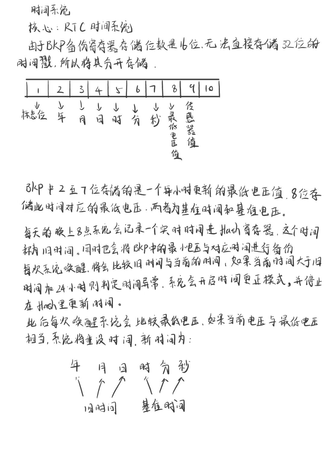
6. Time Fault Judgment and Handling Functions:
This part involves a lot of code and is not convenient to demonstrate; the general principle is explained here.
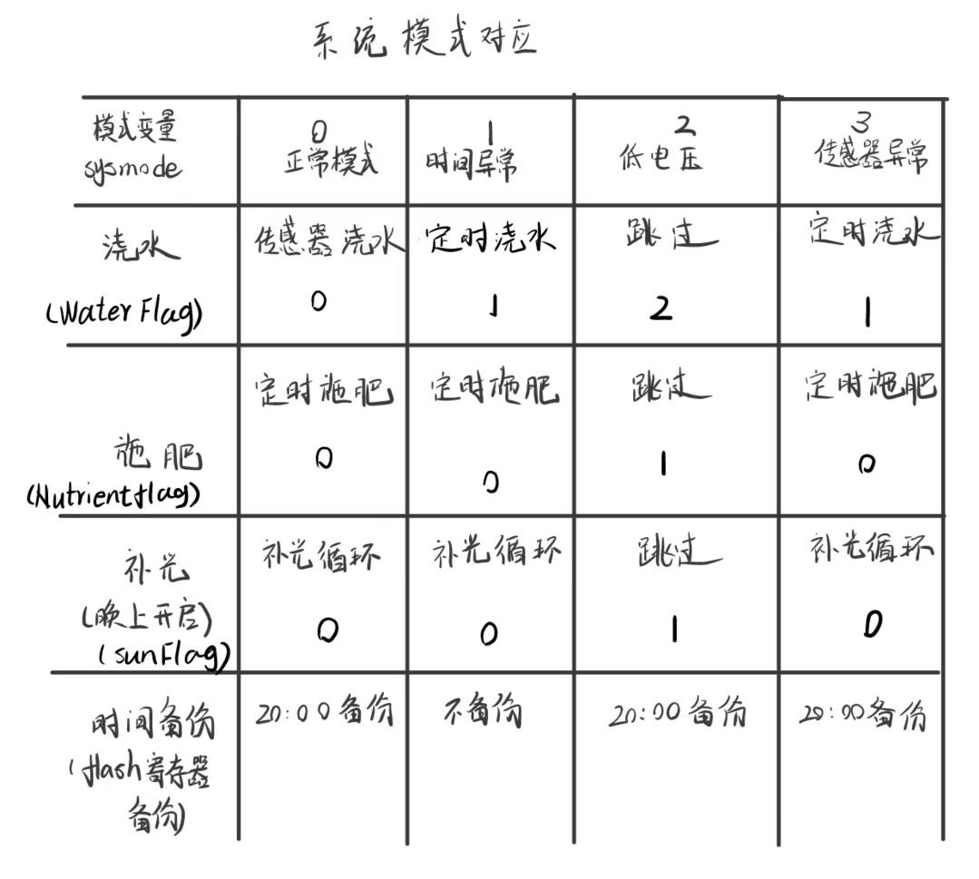
7. System Structure:
This section involves a large amount of code, making it inconvenient to demonstrate. The general principles are explained here.
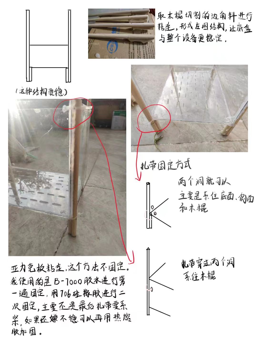
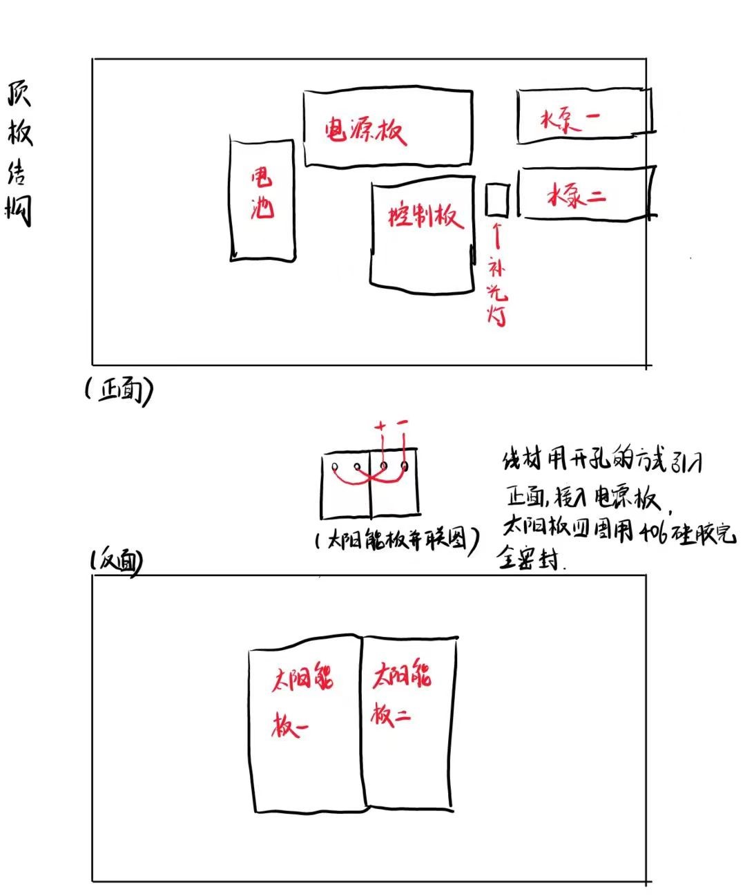
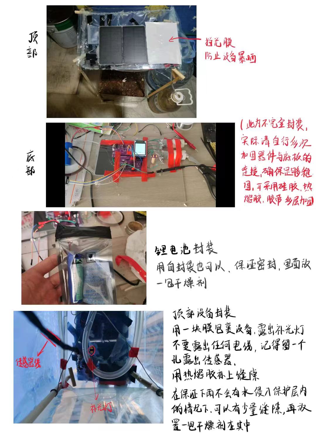
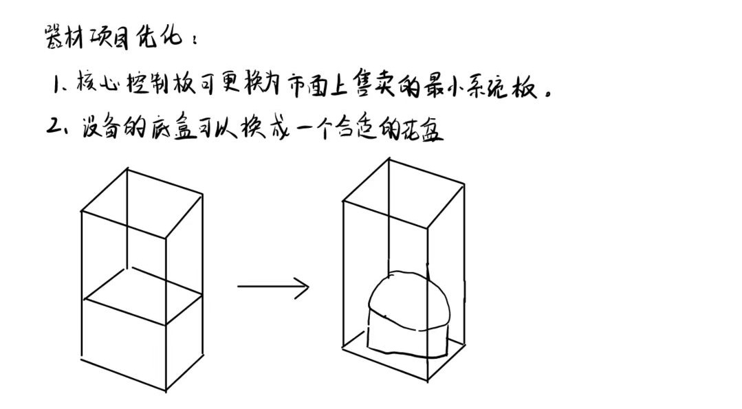
Physical Setup Design
: Detailed setup steps are shared; the solution is not fixed, and you can explore better options yourself.


Bill of Materials and Price Estimation
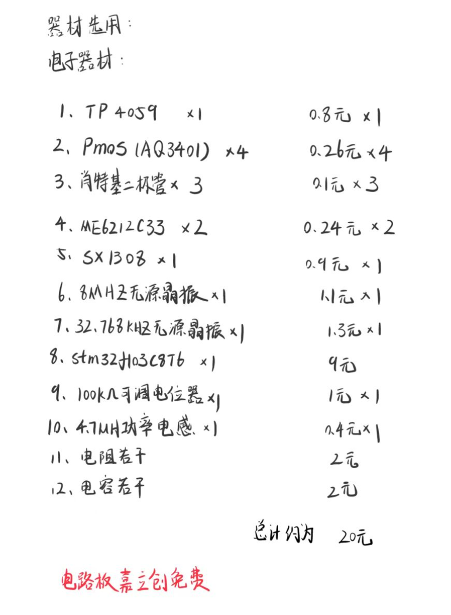

: Notes:
I. Project Defects:
1. Power Board Defect
: A self-locking switch can be designed on the connection circuit between the lithium battery and the power board. This design makes subsequent device connection, programming, and debugging more convenient. Furthermore, due to the special nature of the RTC clock (no power interruption or restart), this design allows for better calibration and setting of the RTC clock value.
2. Control Board Defect:
Please delete all designs related to the backup battery module, or do not solder this module. This module will cause the control board to malfunction. Deleting this module will not affect the normal function of the device.
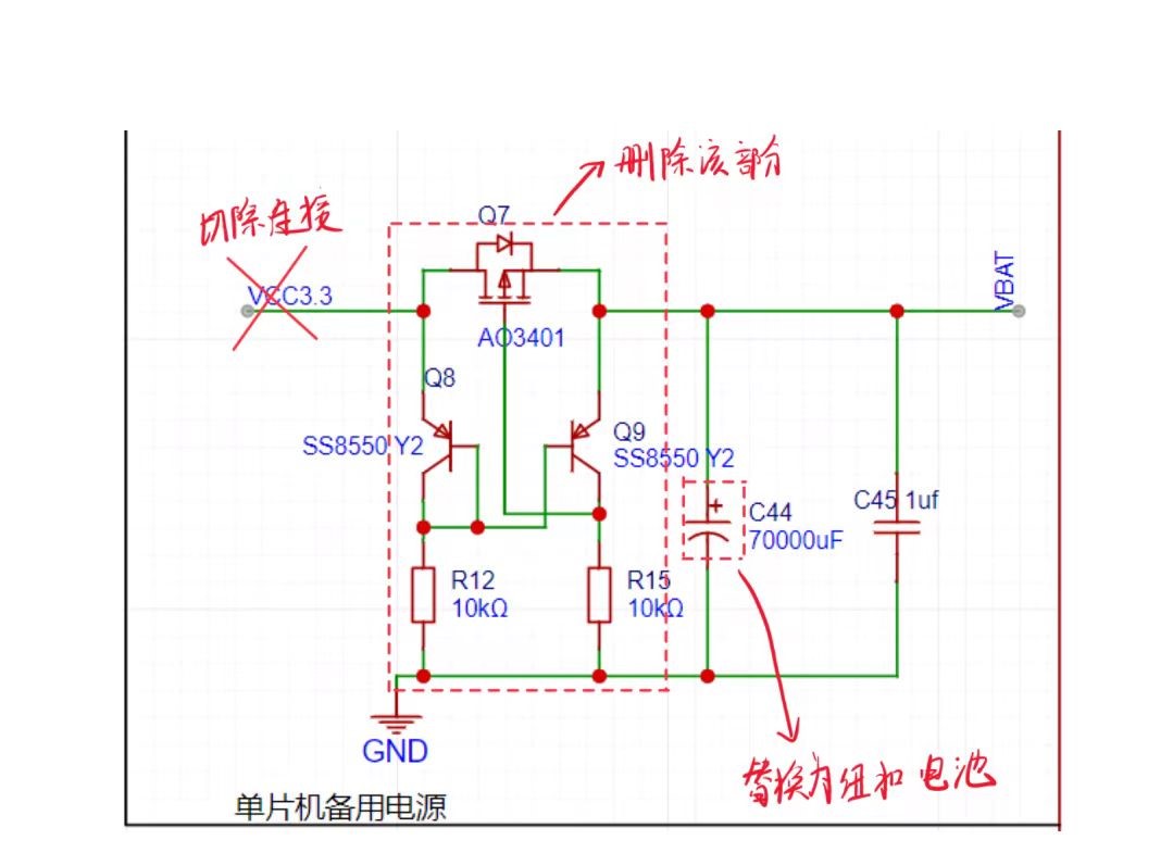
If you want to activate the backup battery function:
First, disconnect the backup battery module from VCC3.3V.
Second, delete the redundant backflow prevention circuit.
Third, replace the supercapacitor with a button cell battery with a voltage not exceeding 3.3V.
(If you have a good solution for using supercapacitors as backup batteries, I would greatly appreciate it if you could share it with me.)
3. Packaging Defect:
While the film covering the entire circuit board provides good protection, it makes equipment repair difficult. Designing a separate casing for the equipment would solve this problem well, but this method is too costly and has not been implemented yet.
4. Circuit Layout Defect:
Some resistors are 0603 gauge; these can be changed to 0805 gauge.
Usage and Debugging Instructions:


Actual Testing


 京公网安备 11010802033920号

 MI-P5VM-IYX


