
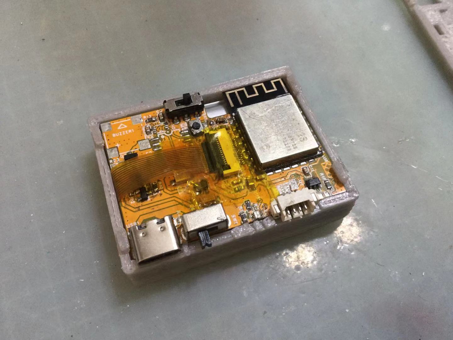
This project involves
an open-source development board
equipped with an ESP8266, a screen, and other hardware. The board features low manufacturing cost, high integration, and expansion I2C/serial interfaces, allowing for the connection of any external expansion modules. It can
be used
as:
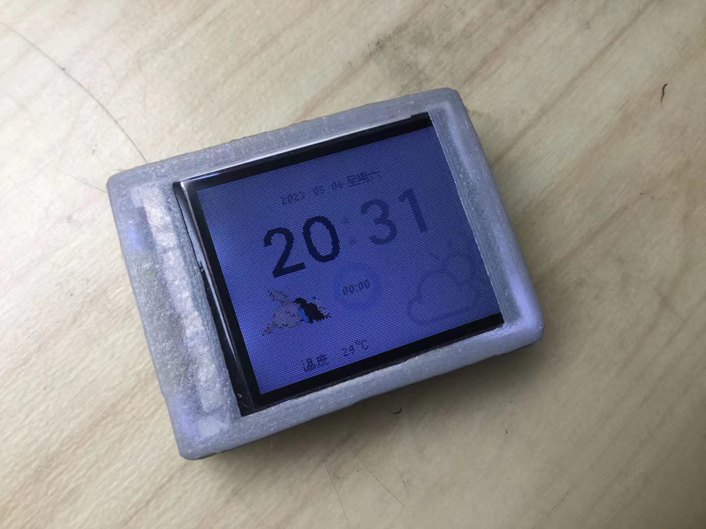
a desktop weather forecast
, calendar,
timer
, bicycle speedometer,
mini server
, etc. There are currently three
hardware versions: V1 (deprecated and no longer maintained, but can be used as a circuit design reference ); V2 (mobile device version) integrating USB to serial port, lithium battery charging, RTC clock (with LDO for hold), geomagnetic sensor, single-channel touch, buzzer, serial communication interface, and TFT screen interface; and V3 (plug-in standby version) integrating USB to serial port, button battery interface, RTC clock, IO expansion chip, single-channel touch, buzzer, I2C interface, and TFT screen interface , with an accompanying IO expansion board V1 for expanding IO ports, I2C, and power supply . Note: 1. The TFT screens used are all 1.8-inch 128*160 from Yaoyuan Hong Technology ( available on Taobao). An LCD screen driven by an ST7735 (plug-in type) is currently priced at 6.8 yuan with free shipping. Link: https://m.tb.cn/h.Uy2YaVL?tk=frWkdKeius6 2. The V2 version uses a 3.7V lithium battery with a 1.25mm pitch connector. It is compatible with dimensions up to 40mm in length, 23mm in width, and 5mm in thickness. The V3 version uses any type of battery with a 3VCR2032 connector and 1.25mm pitch connectors. 3. In the schematic, the XC6210 can be replaced with the ME6211A33, allowing ceramic capacitors to replace tantalum capacitors, but the package needs to be modified. 4. Before board making, please carefully review the schematic and PCB, paying attention to version compatibility. 5. Only the V2 version 3D printing model (A/B compatible) is uploaded as an attachment. It is in .stl format and is divided into upper and lower parts. When slicing, please ensure the flat surface is at the bottom. Precision requirements are not high, but if the clips are difficult to fasten, you may need to use a file to smooth them down. Be careful not to break the clips. The example program is open source on Gitee. For details, please see the Gitee documentation: https://gitee.com/CPSOe/OeScreen. License: MIT V2.2. Main development progress: #2022 8.1? PCBV1.0 test screen socket reverse RH6030 cannot use buzzer driver circuit error 8.23 PCBV1.1 corrected the above error, changed some pins, added a 10uF capacitor to EN to improve the success rate of automatic programming, added I2C interface SHT30 resistor changed to 10K 8.25 PCBV1.1 test except for screen distortion, the rest of the functions are normal 8.28 PCBV1.1 changed driver settings, removed the LED on the module, the screen drives normally, but multiple programming failures, the module overheating may be due to the chip SPI pin being short-circuited by solder, after heating the SPI pin, programming is successful 12.31 PCBV2.0 drawing completed and initial board making removed SHT30, added clock chip RX8025T, added lithium battery charging chip TP4056, serial port chip changed to CH343P, added power switch, added TFT backlight control circuit #2023 1.12 PCB V2.0 soldering completed (the computer couldn't recognize it after soldering; resoldering the Type-C interface resolved the issue). Due to the DTR being pulled down when the CH343P was powered on, GPIO0 was also pulled down, resulting in a persistent download mode and inability to run normally. 1.13 PCB V2.1P: Designed and boarded the CH343P, adding a transistor circuit and making some minor modifications. 2.2 PCB V2.1K: Soldering and programming successful. V2.1K: Replaced the CH343P with a CH340K; test program burned and ran successfully. 3.26 PCB V2.2 B: Testing completed; modified and re-boarded, adding a lithium battery voltage detection circuit and a power supply switching circuit. When there is no USB power, the serial port chip is powered off, switching to lithium battery power. 4.2 PCB V2.2 B: Soldered the CH340K power supply MOSFET; design error found, corrected. 6.4 PCB V2.2 Version B was changed to V2.3 , removing the level conversion chip. An XC6206 was added to maintain RTC operation. The lithium battery voltage was reduced to 3.3V. An electronic compass QMC8553L was added. 6.25 PCB V2.3. Version B was changed to V2.3, and V2.2 was changed to V3.0 (long-term power-on standby design version). V3.0 removed the level conversion chip, changed the power supply layout, replaced the lithium battery with a non-rechargeable button cell battery (3VCR2032 with 1.25V wire), removed the lithium battery charging circuit, kept the I2C expansion interface unchanged, and added an I2C to parallel port chip (PCF8574T) and terminal blocks for expanding I/O. 7.14 PCB V2.3. All hardware design and test program verification were completed, and the codebook project development began.


 京公网安备 11010802033920号

 177-710-5-9GP6J7-24LCN


