Project Description:
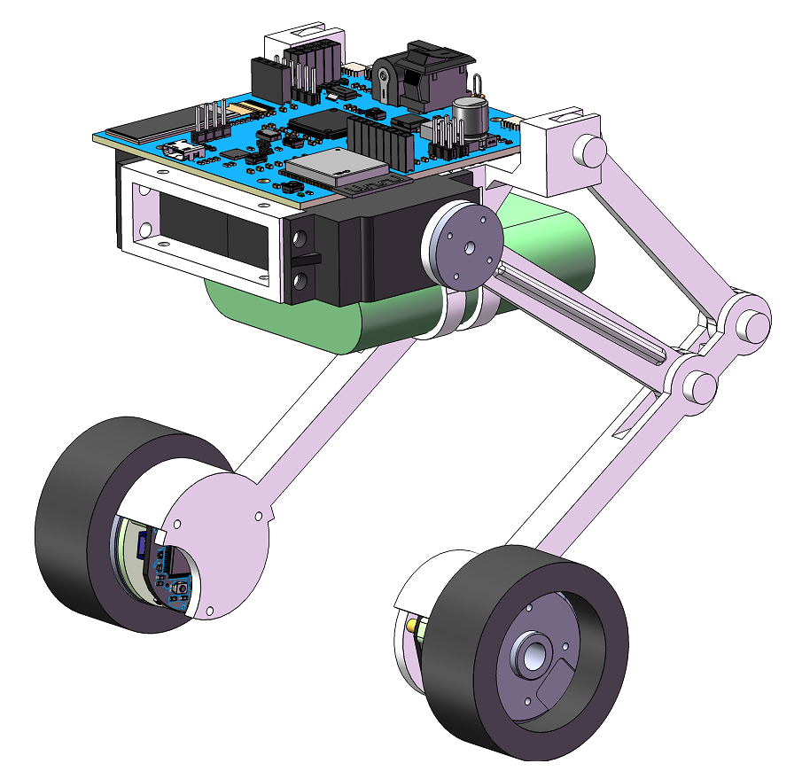
Foot-wheeled robot. Inspired by the Ascento robot, this project boasts low cost and high performance, and its remarkable features, such as self-balancing, climbing stairs, and jumping, are all implemented in this project.
Open Source License:
This project uses the CC-BY-NC-SA 3.0 open source license, i.e., Creative Commons Attribution-NonCommercial-ShareAlike.
CC: Creative Commons License;
BY: Attribution, you must give appropriate attribution, provide a link to this license, and indicate whether modifications were made (to the original work).
SA: ShareAlike, if you remix, transform, or build upon this work, you must share and publish your contributions under the same license as the original.
NC: NonCommercial, you may not use this work for commercial purposes.
Project Features:
Self-balancing, rapid movement, maneuvering, obstacle jumping, side tilting, height adjustment, leg height adjustment, Wi-Fi remote control, PS4 controller Bluetooth wireless remote control, wireless parameter tuning, parameter feedback and display, etc.
Project Attributes:
This project is being publicly released for the first time and is an original work by the author. This project has not won any awards in other competitions.
Project Progress:
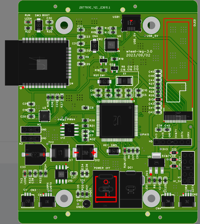
1. Main control board hardware schematic design and PCB design inspection completed.
Reserved interfaces: MPU6050 interface, OLED interface, reserved serial port, reserved I/O. To improve system completion rate, these interfaces are reserved for some circuit designs and can serve as alternative interfaces if problems arise in the original circuit design.

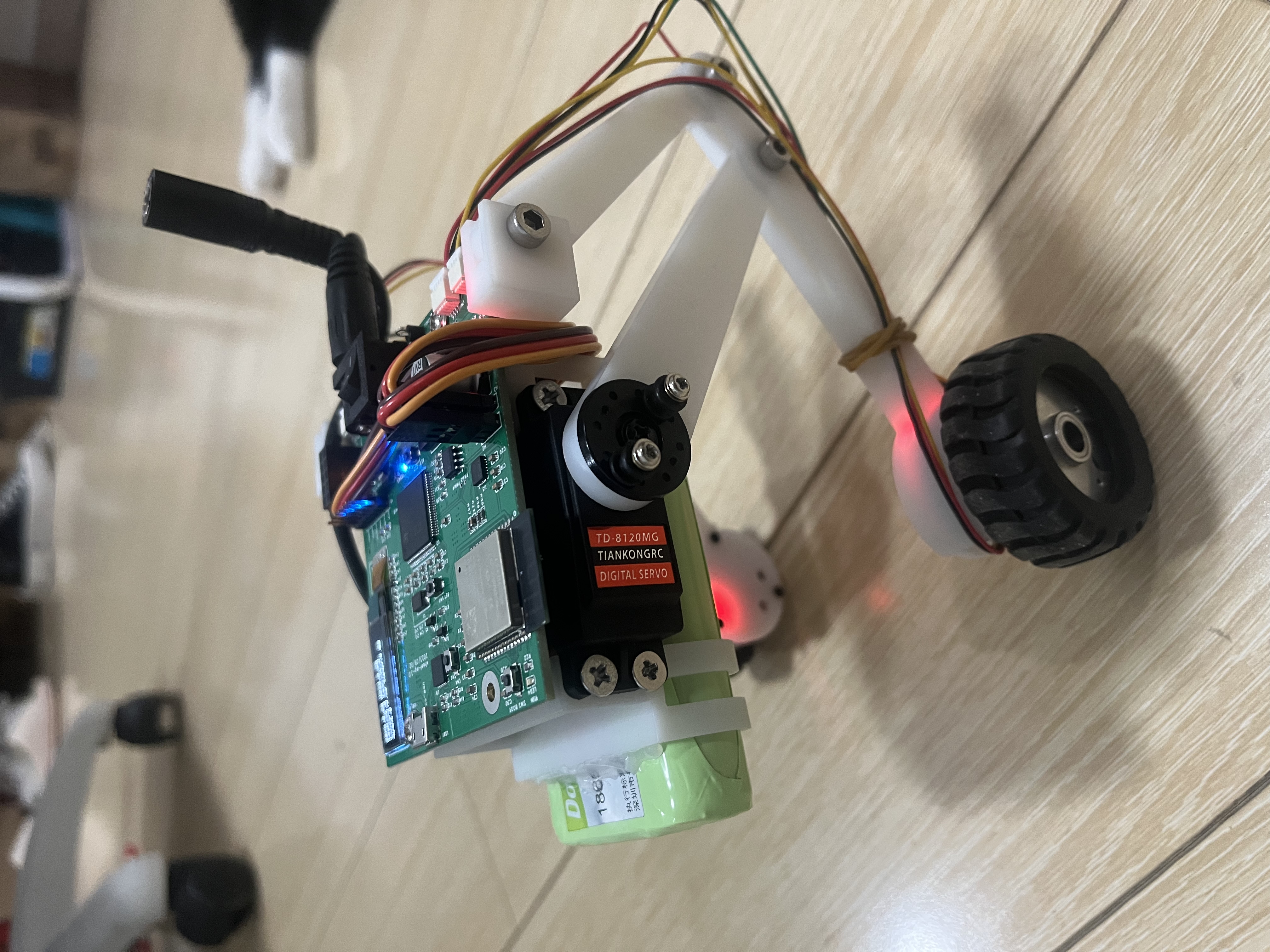
2. Main control board prototype has been delivered. After debugging, the hardware functions have basically achieved the expected functions. Hardware debugging details are as follows:
1) The D+ and D- terminals of the ESP32 USB were reversed; after swapping them, the function is normal.
2) The IIC of the MPU6050 was not connected to a pull-up resistor; after connecting the pull-up resistor, the function is normal.
3. Structural design completed; next step is to prepare for prototyping.
4. Hardware improvements were made, with the following
modification records: 3.01. The D+ and D- connections of the ESP32 USB were reversed. (Modified) 2. The IIC of the MUP6050 was not connected to a pull-up resistor. (Modified) 3. The 3.3V from other sources was unstable. The 3.3V needed to be stepped down from the circuit board. Connect 7.2V to 5V, remove the 5V voltage, and supply 7.2V to the 3.3V regulator chip. (Modified) 4. The servo PWM needed a pull-up resistor; otherwise, the servo would suddenly return to zero during reset due to the low level. (Modified) 5. The D2_LED network label was incorrect; it should be D23_LED. (Modified) 6. The 5V voltage from the FOC motor was insufficient, so the 5V network label was removed, and 7.2V was connected to 5V. The 5V voltage was removed, and supply 7.2V to the 3.3V regulator chip. (Completed) 8. The USB connection was disabled. ID pin configuration modified. 9. Spare interface removed, modified. 10. 7.2V enable control ENA removed, modified. 11. Three electrostatic discharge (ESD) protection devices for USB1 removed, completed. 12. CN1's U6_TX and U6_RX were incorrectly labeled as U2_TX and U2_RX. 13. All interface pins should be marked with standard silkscreen or the interface connection direction should be indicated.
5. The structure has been further improved:
1) The structural strength of the leg components has been strengthened.
2) The battery position is adjustable, thus changing the zero position

design principle
. The hardware design is as follows:
The power supply uses three 18650 batteries, which can provide 12V voltage and 3000mAh capacity. The 12V can directly power the FOC motor, and the FOC motor outputs 5V to power the main control board, thus saving the 12V to 5V power supply circuit. The 12V to 7.2V DC/DC chip TPS5450DDAR with a maximum current of 5A is used to power the servo.
The main control chip is the STM32F407, with ESP32 providing wireless remote control functionality. It can be controlled and its parameters adjusted via Wi-Fi, and can be remotely controlled via Bluetooth using a PS4 controller. The reason for not directly using the ESP32 as the main control chip is its unacceptably slow compilation and programming speed.
Using the STM32 allows for programming with J-Link, and even with the Arduino framework, the STM32's compilation speed is fast enough on the VS Code Platform I/O platform.
IMU: Uses an MPU6050 communicating with the STM32 via I-IC
. OLED: Uses a 0.91-inch OLED screen communicating with the STM32 via I-IC.
EEPROM: Uses an AT24C04 communicating with the STM32 via I-IC.
FOC Motor Interface: The FOC motors are SimpleFOC 2805 motors, which greatly improve the robot's balance.
Servo Interface: Uses 20kg servos for leg power; these high-power servos are intended to change the center of gravity, maintain left and right balance, and enable jumping.
Programming and debugging interface: STM32's SWD interface and one debugging serial port
. Power detection: one STM32 ADC channel.
Micro USB 5V & USB-UART: ESP32 programming and debugging circuit.
5V to 3.3V: The power supply circuits for chips such as STM32, ESP32, and MPU6050
have multiple 5V power supplies, and BAT760-7 diodes are used for circuit protection.
The structural design is as follows:
1) Weight control is weight reduction;
2) Achieving linear circular motion of the legs.
Software Description:
This project is developed using VSCode + PlatformIO, and uses the Arduino library + FreeRTOS operating system to create multi-task management. Functions of each part:
1. STM32 main control function: For the vehicle body whose center changes with leg movement, its balance and forward steering control uses multiple LQR controllers. LQR controllers can greatly improve the robot's balance ability and control effect.
2. ESP32 wireless function: The wireless function can be adjusted and remotely controlled via Wi-Fi using the WheelFun Technology mobile app, or via Bluetooth using a PS4 controller. Physical
demonstration:
Main control board

, wheeled robot

design precautions:
During project debugging and use, the PS4 controller should not be connected to PS4 or other devices such as mobile phones, otherwise the PS4 controller will not be able to connect to the ESP32 unless a new ESP32 chip is replaced (reason unknown).
Other:
The main control program and wireless program source code, structural model files, and 3D printing files of this project are all open source in the attachments, and are all final versions.
The project includes a mobile phone debugging and remote control app: Link: https://pan.baidu.com/s/1gNYY2oHdPqBM7ljvdAj2Vw Extraction code: xjh6
The core technologies of the project are FOC motors and LQR algorithms.
Most of the features have been implemented and demonstrated in the demo video; the jumping capability will be tested later.
Other demo videos and materials: https://www.bilibili.com/video/BV19w411r7s1/?vd_source=b308842dab6371bccb1b4b5030895bf6 (see personal homepage)
Other materials: https://gitee.com/yigelunzi/wheel-legged-robot.git


 京公网安备 11010802033920号

 HEDS-5545-E01


