Project Description:

This is a large-bezel, full-screen CNC electronic load cell. The casing is made of resin 3D printed, and the overall dimensions are 54x88x84mm. Because its shape resembles a computer tower, I named it "Xiao Shou No. 1," abbreviated as XS1. The XS1 provides one Type-C port for communication and power supply (5V 2A power supply recommended), and also has a built-in 18650 power battery, prioritizing external power when both are powered simultaneously. The screen is a 3-inch 480x854 high-resolution capacitive touchscreen. Note: This project does not prioritize cost-effectiveness; it is primarily for learning and research. I previously stumbled upon this MCU with 8MS RAM and an RGB interface, thinking of making a small gadget with a touchscreen, and then I saw this project and decided to do it. Compared to similar electronic loads, the cost is about 50 yuan more, mainly due to the touchscreen cost.
Video Link: https://www.bilibili.com/video/BV1Ae411X7fm/
Project Parameters
: Dimensions: 54x88x84mm (width x length x height).
Interaction Method: 3-inch 480x854 TFT screen, capacitive touch, 2 tactile switches.
Power Supply: 5V Type-C interface, built-in 18650 battery.
Load Interface: Type-C port, XT30 port.
Sampling Range: Voltage 0-60V, Current 0-4A.
Load Capacity: Constant Current 0-4A, error <0.04A | Constant Voltage 0-48V, error <0.2V | Constant Resistance 1-1000R, error <5%, Constant Power 0-100W, error <5%.
Load Capacity: 30W for long-term operation, 100W (10S) for short-term operation.
Protection Method: Overcurrent protection, overvoltage protection, overtemperature protection, reverse connection protection.
Open Source License
: This project is licensed under the "CC-BY-NC-SA 4.0" Creative Commons Attribution-ShareAlike 4.0 license. Commercial use is prohibited. Please indicate the source when reprinting.
Project Attributes:
This project is being publicly released for the first time and is my original work. This project has not won any awards in other competitions.
Project update
history lost, omitted...
2023/11/2 Changed some resistor and capacitor values on the power board, merged some resistors and capacitors from different brands. Re-uploaded the list, no PCB re-fabrication involved.
2023/11/22
Core board updated to V2.0. The original version's power IC was constantly overloaded, which may have caused problems. After replacing the board, it is not very compatible with the original inner shell. To use the previous inner shell, a small amount of material needs to be manually removed from the bottom. Core board modifications are as follows:
Removed the serial port pins on the USB end, replaced with a regular USB connection method, removed the serial port selection DIP switch, removed CH340.
Added a Wi-Fi and Bluetooth module for serial communication.
Removed the onboard speaker, replaced the power amplifier circuit, increased power, and provided a 2-pin terminal for connecting an 8-ohm 2W speaker.
Replaced some I/O pins.
Replaced the power IC, output current up to 1.2A.
Project Introduction
1. The hardware
PCB board is divided into two parts, a core board and a power board, which are connected by a double row of pins. The two boards are arranged somewhat compactly, with resistors and capacitors primarily using 0603 packages and a 4-layer board design. The main controller is Huaxin Microelectronics' SWM34SVET6, a Cortex-M4 core with 8MS dram, capable of driving an RGB interface display. The core board mainly includes MCU main control peripherals, power supply and charging/discharging circuitry, speaker, USB and serial communication, and display circuitry. The power board mainly includes load interfaces, PD protocol circuitry, fan drive, analog sampling, MOSFET drive, and feedback circuitry. The core board has complete interfaces and can be used independently as other core boards.


1.1 Framework

1.2 Structure
The entire unit is roughly divided into a casing, PCB, fan, heat sink, screws, and accessories. The two PCBs are connected by a double row of pins and can be separated. Internal air is exhausted to the back by the fan, and all interfaces are also located on the back. The front is a single 3-inch touchscreen.


1.3 Principle Introduction and Hardware Analysis
The electronic load, as a power-consuming device in the environment, can be simply understood as a high-power adjustable resistor. In actual circuits, the conduction current of a MOSFET is controlled by adjusting its gate voltage. More precise output can be achieved by controlling the MOSFET through the MCU's DAC or PWM.
Common operating modes for electronic loads include constant current, constant voltage, constant power, and constant resistance modes. Constant power and constant resistance modes involve calculating the input voltage and then feeding it back through current, similar to the constant current mode. Constant voltage mode feeds back the voltage to the MOSFET's gate voltage; therefore, I designed both current and voltage feedback circuits in the hardware, and controlled their operation via the MCU's I/O ports.
1.3.1 Constant Voltage and Constant Current Drive Circuit
The drive circuit diagram in constant current mode is shown below. In the diagram, the MCU's CC_MODE pin outputs a high level, and CV_MODE outputs a low level. Q3 is on, and Q2 is off. At this time, the current feedback circuit is working. The voltage across the sampling resistor in the load loop is amplified by the operational amplifier and enters the IN- port of U5.3. The DAC pin enters the IN+ port of U5.3, forming a stable output to the gate of Q4 [MOSFET].
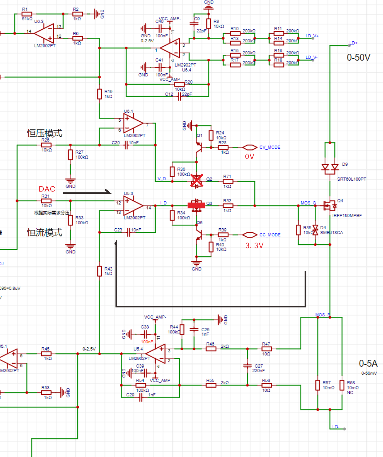
The driving circuit diagram in constant voltage mode is shown below. In the diagram, the MCU's CC_MODE pin outputs a low level, and the CV_MODE pin outputs a high level. Q2 is turned on, and Q3 is turned off. At this time, the voltage feedback circuit is working. The load voltage is reduced by the differential circuit and then enters the IN+ port of U6.1. The DAC pin enters the IN- port of U6.1, forming a stable output to the gate of Q4 [MOSFET].

1.3.2 Power Supply Circuit
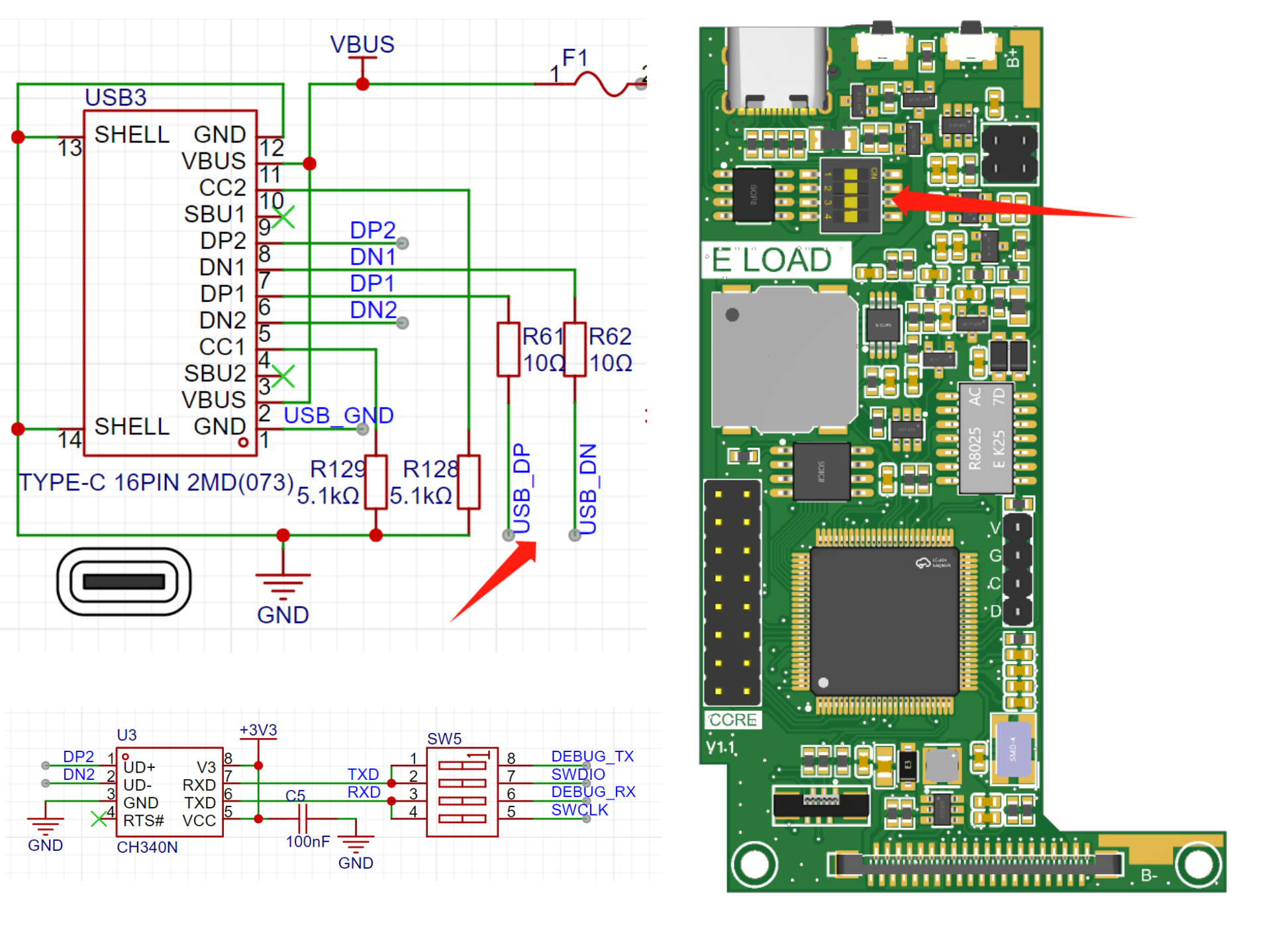
XS1 provides a Type-C port for power supply. Note that the power supply voltage range must not exceed 6V. It is recommended to use a 5V 2A power supply. When the Type-C power supply is plugged in, 5V first enters the subsequent stage through the built-in diode of Q13. At this time, the gate of Q13 is grounded (USB_GND is connected to pin 1 of Type-C, utilizing the characteristics of the Type-C connector, pins 1 and 12 are connected and grounded), so Q13 is turned on, and the voltage at point A is close to 5V. Q12 is turned off because there is 5V at its gate. The battery enters the subsequent stage through the internal diode of Q12. Since there is 5V at point A, the battery is not in a working state. When the Type-C power supply is removed, the gate (G) of Q13 is left floating and thus cut off, the gate (G) of Q12 becomes 0V, Q12 conducts, and the voltage at point A approaches the battery voltage. This circuit reduces energy loss compared to directly connecting diodes in series. The subsequent stage uses Q14 for software shutdown and SW1 and Q8 for button power-on.

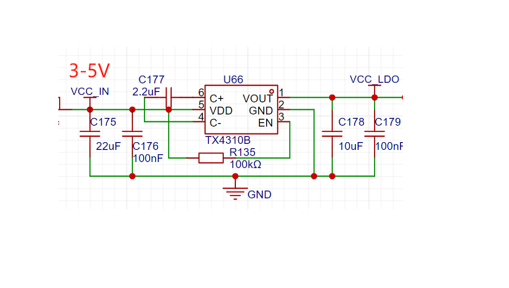
Since the input voltage range is 3-5V, the subsequent stage uses a TX4310B charge pump DC-DC chip, which can generate a stable 3.3V output voltage from a 1.8V to 5V input with an error of ±4% (this also causes the DAC output to vary slightly with input voltage fluctuations).
1.4 Interface
All XS1 interfaces are located on the back, as shown in the image below. Two XT30 interfaces form a 4-wire measurement method. When testing the power supply, the positive and negative terminals need to be connected separately (V+ and I+ to positive, VI- to negative). The advantage of the four-wire measurement method is that voltage and current are separated, and voltage acquisition does not pass through the current loop, resulting in less voltage drop and higher accuracy. Alternatively, a Type-C interface can be used directly (its internal two power supplies are used to connect to V and I respectively, and there is no shorting on the female connector). If a Type-A port or DuPont wires are needed, an interface board can be made to expand the Type-C port. The fan interface is on the power board and is a 2-pin terminal. The fan drive circuit supports PWM speed control; the current firmware uses I/O level drive, but a future update will allow for fan speed adjustment based on heatsink temperature.

The bottom Type-C port is mainly for power supply, USB communication, and serial communication. Internally, DP1DN1 connects to the MCU's USB pins, and DP2DN2 connects to the CH340, which is the serial port function. This saves on USB ports but sacrifices the reversible connection capability of the Type-C. The serial port is controlled by a DIP switch on the core board to determine whether to connect to the ISP serial port or the debug serial port. There is also an SD card slot at the bottom, but its function has not been tested.
1.5 Circuit Diagram Simulation:
For more complex circuits with logic components, it is recommended to run the circuit using simulation software first to check if the results are as expected.


2. Software:
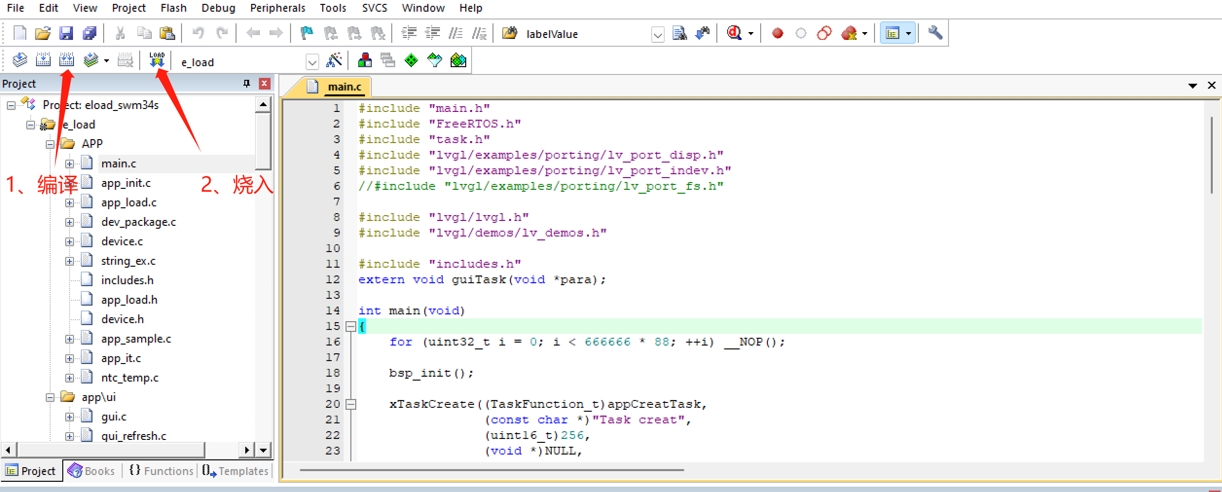
The MCU code is based on FreeRTOS+LVGL, the IDE uses Keil uVision 5.38, and the GUI is generated using SquareLine Studio, which is simple and efficient.
2.1 Firmware Update:
The core board has USB and serial ports, which can be used for IAP and ISP firmware updates. The code for these updates is not yet implemented. Firmware can be flashed using J-Link via the SWD interface on the core board. Open the Keil project, click compile, and then flash the firmware.
2.2 GUI Interface
: The interface is generated using SquareLine Studio, a visual drag-and-drop UI editor that allows for quick and easy creation of beautiful graphical user interfaces for embedded and desktop applications. Official website: https://squareline.io/, available for free personal use after download and installation, with the limitation of designing only 5 UI interfaces and placing 50 controls. Animation effects can be easily and intuitively achieved through simple software settings (I learned something new and gained valuable experience from this project).

The main interface shown above is divided into several parts: sampling display, setpoint setting, mode setting, and waveform display. There are two ways to set the setpoint: simply press the "+1", "+0.01", etc. buttons next to it, or click the setpoint label to bring up a numeric keypad for quick setting. Multiple modes are selectable, and an indicator light is displayed below the selected mode. Two waveforms can be displayed.
2.3 Debugging Assistant:
A debugging software based on QT5 (the same debugging assistant used for soldering boxes previously), used to view load sampling values, signals, and to calibrate and modify parameters. The software uses serial communication; the serial port number must be set before use, defaulting to 115200, 8, 1, no parity. After connecting the device, click the "Connect" button to perform other operations. [MCU side code not adapted].

Read and modify parameters
, view real-time data,
calibration coefficients ,
view waveforms.
2.4 Code analysis.
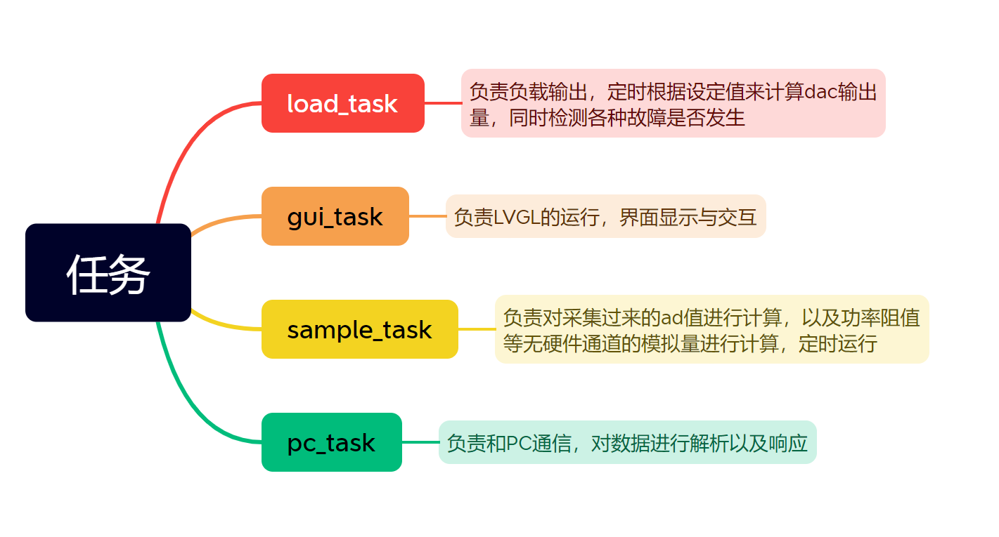
The code is based on the FreeRTOS operating system and has four main tasks: load_task (load output task), gui_task (screen display interaction task), sample_task (analog quantity calculation task), and pc_task (communication task with PC).
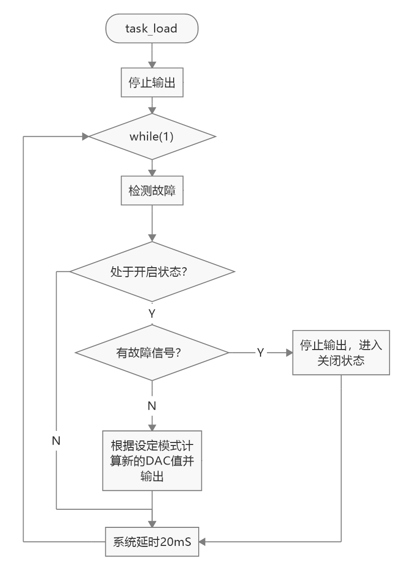
The main focus is on load_task. The task is executed periodically by vTaskDelay(pdMS_TO_TICKS(20)), which is executed approximately every 20ms. After entering the while(1) loop, the loadFaultCheck() function is called to check for faults such as over-temperature and over-pressure. If there are any, the output is stopped. If not, the corresponding mode is entered to calculate a new DAC. The process is as follows:
The MCU has 8Msdram built in. I designed an SPI flash (w25Q64) on the board and accessed it through the MCU's SFC interface, mapping it to the MCU's storage space so that some constants are directly defined in the code in the SPI flash. These need to be initialized before use and additional download algorithms are provided. All relevant information is in the attachment.

2.5 Software Calibration
As mentioned earlier, the TX4310B charge pump chip was used. Although its input range is 1.8-5V, its output varies with the input voltage, with a datasheet-stated error of 4%. Ideally, a DAC's output should be proportional to the set value. However, in reality, errors can occur due to factors such as temperature and operating voltage. Here, we mainly discuss operating voltage; at the same set value, the lower the operating voltage, the higher the DAC output. For example, in constant current mode with a 1A set value, when using USB power (voltage 5.06V), the TX4310B outputs 3.365V, and the DAC output is 0.602V. Switching to battery power (voltage 3.57V), the TX4310B outputs 3.332V, and the DAC output is 0.63V. The difference is 30mV, which translates to an error of approximately 40mA in current output.
There are two solutions. One is to modify the power supply in hardware, using two 18650 batteries to ensure the input is above 5V, and then converting it to 3.3V using a high-precision LDO such as the AMS1117. The other is to calibrate in software, by sampling the operating voltage and calculating the actual DAC drift voltage, which is then factored into the settings. However, since the SWM34S's ADC sampling is also affected by the operating voltage, error compensation is needed during post-sampling calculations. Overall, the error is around 10mA in constant current mode (0.1-2A) (not considering temperature drift).

3. Assembly:
First, place the button caps into the inner case, then fix the heatsink to the MOSFET on the power board (the heatsink has pre-drilled holes), and add a heatsink between the heatsink and the MOSFET. I used a ceramic heatsink, which is slightly more expensive. Note that the NTC resistor on the power board must touch the heatsink; thermal grease can be applied. Connect the two boards with header pins and fix them to the inner case. Then place the fan in the corresponding position and secure it with screws inserted from the back. Finally, attach the LCD screen to the slot on the front of the inner shell, and connect the FPC cable to the core board from the bottom gap. Then, put on the outer shell; if it's loose, secure it with 2.5mm screws.


4. Function Introduction
: Primarily used as an electronic load, it can also play music and pictures from an SD card. With a built-in battery and clock chip, it can also be used as a desktop clock.
4.1 Electronic Load
Operating Modes:
Supports constant current, constant voltage, constant power, and constant resistance modes.
Fault Protection:
Supports over-temperature shutdown protection, over-current shutdown protection, over-voltage shutdown protection, and reverse connection protection. The fan automatically turns on when the temperature exceeds the set value.
Waveform Display:
Displays two waveforms, which can be freely bound to sampled values such as load current, load voltage, and heatsink temperature.
Built-in Battery:
Built-in 18650 power battery with high output current, capable of driving a larger cooling fan. The USB port can charge the battery with a charging current of 0.5A.
Numeric Keypad:
The advantage of a touchscreen allows for quick parameter setting. Although there's not much to write, I'm writing anyway, just because I want to.
Charger testing:
It incorporates an FUSB302 chip, supports PD protocol control, and can directly test the charger's output capability in constant current mode. (Code not implemented.)
Voice prompts:
4.1 Built-in speaker, which can play voice prompts in case of malfunction. (Code not implemented)
4.2 Music player:
Built-in speaker and SD card interface, can play music by reading SD card files. (Code not implemented)
4.3 Desktop clock ornament :
Built-in clock chip and battery, can be used as a small clock ornament when idle. (Code not implemented)
4.4 Timer:
The timing can be set, and a voice prompt will sound when the time is up. (Code not implemented)
4.5 Metronome:
The beat frequency can be set, and it will simulate beat sounds. (Code not implemented) (Ignore sections
4.2-4.5)
5. Usage and Testing:
Connect the power supply to be measured through the Type-C port or XT30. The XT30 is a 4-wire measurement method. Power can be supplied via USB or internal battery. Press the power button on the back to turn on the device. After the logo is displayed on the screen, the main interface will appear. Select the corresponding mode and setting, and press the start button. Press the power button on the back to bring up the power-off dialog box, where you can choose to cancel or press the power button.
The test video wiring is as follows. It tests a regulated power supply. To display the current more accurately, a multimeter set to DC current mode is connected in series with the circuit when testing constant current, constant resistance, and constant power modes. Constant voltage mode primarily tests the load-carrying capacity of current source type power supplies or power supplies with current limiting protection (the power supply is in its maximum current output state, equivalent to a current source). I added a sheathed resistor in series for current limiting, simulating a floating charge state to prevent the power supply from burning out. The multimeter is set to DC voltage mode; note that if you previously measured the current, connect the probes back to the voltage interface.


Please refer to the attached video for specific usage.
Project References :
Before designing the project, I read several open-source projects, which were very helpful. Some hardware circuit prototypes referenced the following projects. Thanks to the authors of the following projects for their open-source contributions!
Author: micespring, Digital DC Electronic Load
(https://oshwhub.com/micespring/digital-dc-elecload);
Author: yueyunno1, Electronic Load Crowdfunding Project
(https://www.dianyuan.com/index.php?do=community_topic_show&id=1521907&rc_total=788&rc_start=40#allReply ).
Other
: Because the initial project was to create a small-power mini electronic load, size was limited. Although the current output is 0-4A and the voltage is 0-50V, the power output is limited. Some components, such as fans, heat sinks, and MOSFETs, do not support long-term high-power loads. I bought heat sinks from two companies, 4x4x5cm and 4x4x6cm. The smaller heat sink, under a 30W load, reached 70℃ in about 20 seconds with the fan running, then stopped outputting power. The larger heat sink, under 30W load, could maintain a temperature of over 60℃ for a longer period with the fan running.
I bought an IRFP150MPBF MOSFET from Taobao for 2.6 yuan. It has a certain chance of burning out when outputting around 100W power (3A, 35V), and the overcurrent, overvoltage, and overtemperature protections don't activate. The manual states its PD value is 160W at 25℃, decreasing at higher temperatures, which might be the cause. For higher power output, I suggest replacing it with a MOSFET like the IRFP260, which costs around 5 yuan on Taobao.
3D printing can print only the inner shell, like a bare-bones 3D printer. This provides better heat dissipation than a 3D printer with an outer shell and saves money.


 京公网安备 11010802033920号

 LM78L09K-XX-TU


