This project is a replica of the CW32 development board training camp project from LCSC. This was my first experience with LCSC's 3D printing and panel services. I also quickly learned how to draw panels using SolidWorks and LCSC EDA in a week. I feel that learning with a goal in mind is much more efficient. The specific selection and CW32 programming are covered in the official documentation, so I won't go into detail here. I'll mainly talk about what's not in the official documentation.
The CW32 official documentation
explains
that the code uses a 1ms timer to refresh the digital tube periodically, and
the buttons use CW32's hardware debouncing and interrupts.
Hardware debounce core code
NVIC_EnableIRQ(GPIOB_IRQn);
GPIO_InitTypeDef gpio_initStruct;
gpio_initStruct.IT = GPIO_IT_FALLING;
gpio_initStruct.Mode = GPIO_MODE_INPUT_PULLUP;
gpio_initStruct.Pins = GPIO_PIN_12 | GPIO_PIN_13 | GPIO_PIN_14;
gpio_initStruct.Speed = GPIO_SPEED_LOW;
GPIO_Init(CW_GPIOB, &gpio_initStruct);
GPIO_ConfigFilter(CW_GPIOB, GPIO_PIN_12 | GPIO_PIN_13 | GPIO_PIN_14, (GPIO_FLTCLK_RC10K);
Use mean filtering and two-point voltage calibration to calibrate the ADC value.
Automatic switching between high and low ranges: greater than 4.8V switches to high range, less than 4.6V switches to low range. Calibration method:
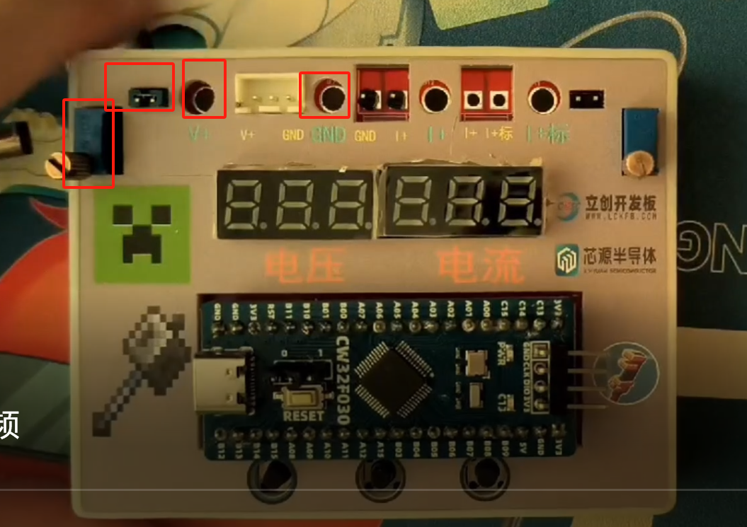
Voltage calibration
: Press buttons 1 and 2 simultaneously to enter calibration mode. Press button 1 to switch the voltage and current to be calibrated. Insert the jumper cap, use a multimeter to measure the three round holes, adjust the adjustable resistor to 5V, and press the third button to complete one calibration. Similarly, perform 11V calibration.
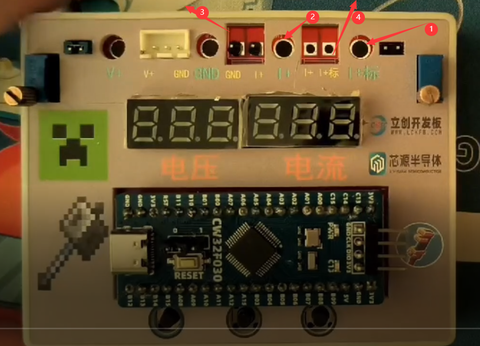
Current calibration:
Insert a multimeter into holes 1 and
2, and connect the external current to be measured into holes 4 and 3. Adjust the current to 0.5A, and press the third button to complete one calibration. Similarly, perform 1.5A calibration.
Calibration and basic operations are demonstrated in the attached video.
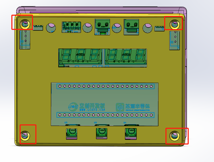
Assembly method
: Use a countersunk head self-tapping M3*8.0 screw-in from the back of the panel to fix it.
The attached file includes the Solidworks assembly file and the exported STL 3D printing order file.
The following issues were noted:
The TL431's pinout was reversed, preventing the use of an external reference voltage. [Fixed]
The current sampling resistor lacked copper plating, resulting in insufficient current. [Fixed] The
copper plating method was not selected as fill, but rather the default divergent method, which may burn out under high current. [Fixed]
The Type-C port from the 3D casing appears to be unused; if Type-C power is needed, it's better to directly plug it into the core board.
The panel's slot size lacked sufficient margin, requiring manual enlargement. [Fixed]
The 3D casing's DC power connector slot size lacked sufficient margin. [Fixed]


 京公网安备 11010802033920号

 FX-104-CFC-A1P9


