The Wandering Earth Spherical Steering Wheel
- by sytnocui 2023/10/18 v1.1
Bilibili video link: DIY Spherical Steering Wheel, Drive Like the Wandering Earth [Hardcore]
0. Tragic Past
If you participated in the 2021 Electronic Design Contest, you'll know that acrylic balls were on the component list. Everyone guessed the topic was a spherical robot, and Bilibili was flooded with videos of spherical robots. We stockpiled a bunch of acrylic balls, spending at least 200 yuan just to buy them. However, due to the pandemic and other reasons, the final control topic was a hospital logistics vehicle that had nothing to do with acrylic balls. While we were breaking down our defenses, the question became what to do with all those acrylic balls.
Acrylic balls were unsaleable, help us!!!
1. Project Description
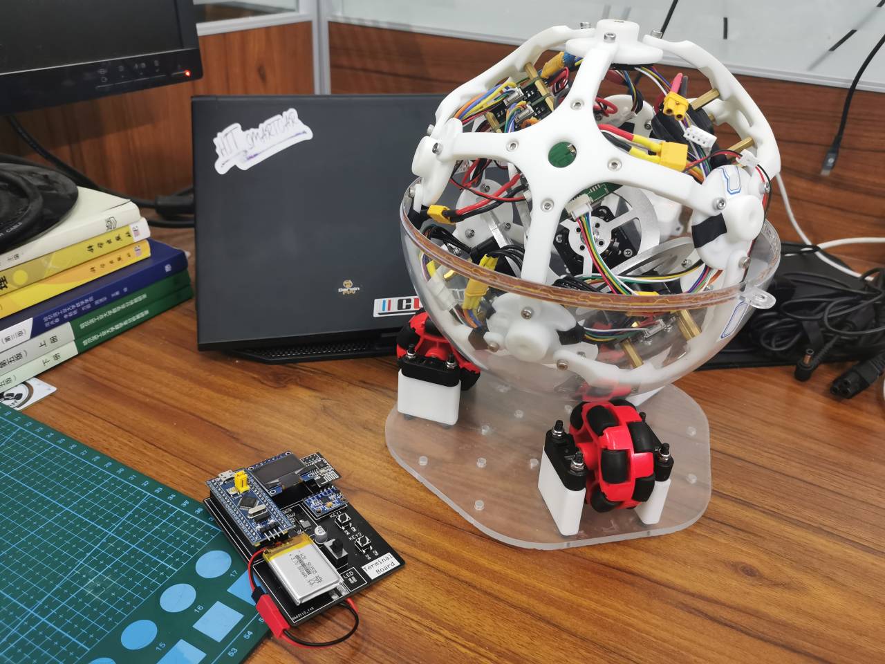
This project aims to create a spherical version of a balanced cube. In terms of overall architecture, three brushless motors drive three orthogonally mounted flywheels, and the entire sphere rests on a chassis composed of three omnidirectional wheels. Omnidirectional wheels allow movement in both the forward direction and axial direction. Therefore, a chassis composed of three omnidirectional wheels allows a balancing ball to perform three-degree-of-freedom, full-attitude free maneuvering. The ball, on the omnidirectional wheel chassis, achieves full-attitude free maneuvering using the principle of conservation of angular momentum. Additionally, the balanced cube created in this project can be connected to a computer and used as a steering wheel for various racing games, with operation similar to the steering wheel in the movie *The Wandering Earth*.
2. Open Source License
This project uses CC-BY-NC 3.0. Please indicate the source when reprinting. Commercial use is prohibited.
CC: Creative Commons License
BY: Attribution. You must give appropriate attribution, provide a link to this license, and indicate whether modifications were made (to the original work).
NC: Non-Commercial. You may not use this work for commercial purposes.
3. Project Attributes
This project is being publicly released for the first time and is my original work. The project has not won any awards in other competitions.
Furthermore, this project is also my senior year innovation project, currently not yet completed. Whether I will pass it on to junior students to enter into competitions is still under discussion.
4. Project-related functions and physical demonstrations:
The balance ball allows for free rotation in all postures;
the balance ball features three-axis angular velocity closed-loop control and assist mode
; and the balance ball's three-axis attitude tracking requires a terminal to enable
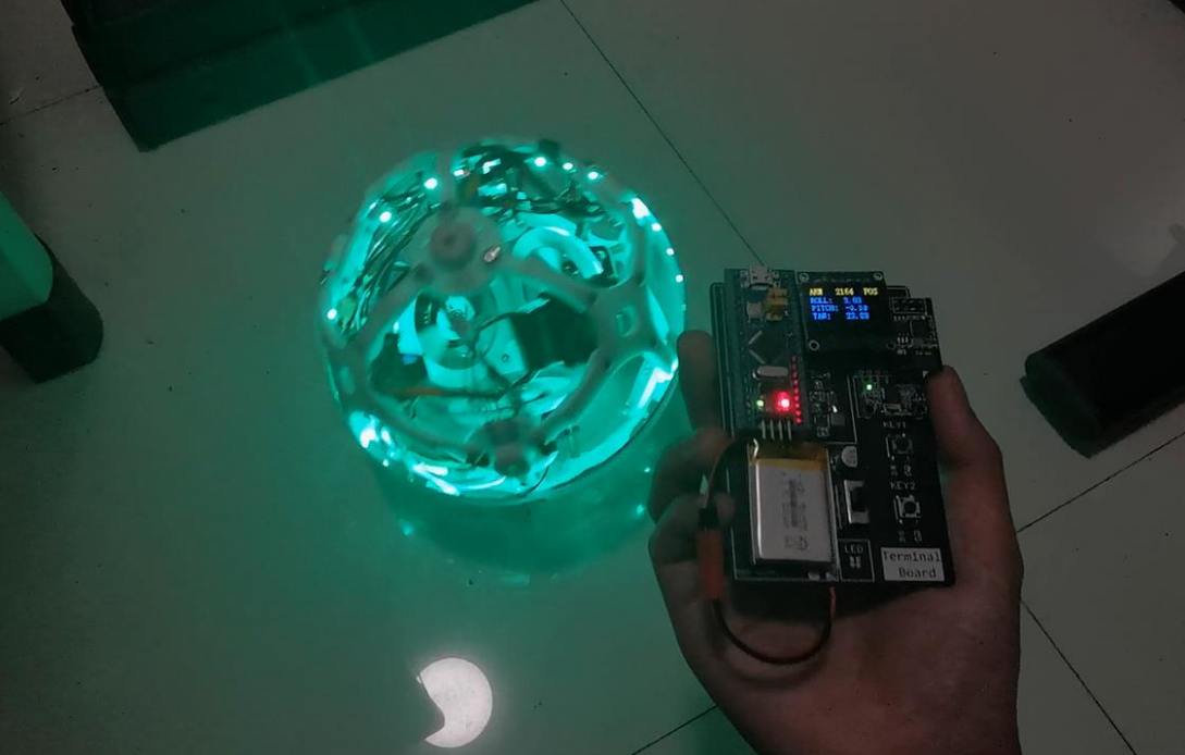
real-time publishing of its own three-axis attitude. It can mimic the steering wheel in the game "The Wandering Earth" for playing various racing games .

5. Design principles:
The project can be divided into three parts: structural design, hardware design, and software design.
5.1 Structural design
: The structural design concept of the project largely references the classic balance cube of Zurich:

As shown in the diagram, the balance cube has six faces, which can be divided into upper three and lower three faces according to their distance from the ground. It is clear that the three orthogonal flywheels of the balance cube are installed on the lower three faces, while the battery, circuit board, etc., are installed on the upper three faces.
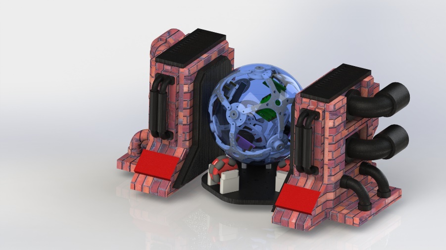
Based on the principles of solid geometry, it is logical to assume that a cube has a circumscribed sphere. Taking the circumscribed sphere of the balance cube and projecting all six faces outwards onto it, we get our balance ball.
The 3D model established based on this is as follows:
5.2 Hardware Design

This project designs a main control board, an FOC driver board, an encoder board, and a gyroscope board. The project hardware topology diagram is as follows:

Among them,
the main control board and the FOC driver board are all powered by cascading and also transmit target commands through cascading via CAN bus.
There are three FOC driver boards in total. Each FOC driver board is connected to an encoder board to obtain the position of the brushless motor and drive a brushless motor.
The main control board is connected to a gyroscope board to read attitude information in real time.
The main control board is connected to an ESP8266 communication module .
5.2.1 Main Control Board
The main control board is a four-layer board, which can be printed free of charge by JLCPCB. It mainly completes WIFI wireless communication, reading gyroscope attitude, attitude calculation, control mode management, and control algorithm operation.
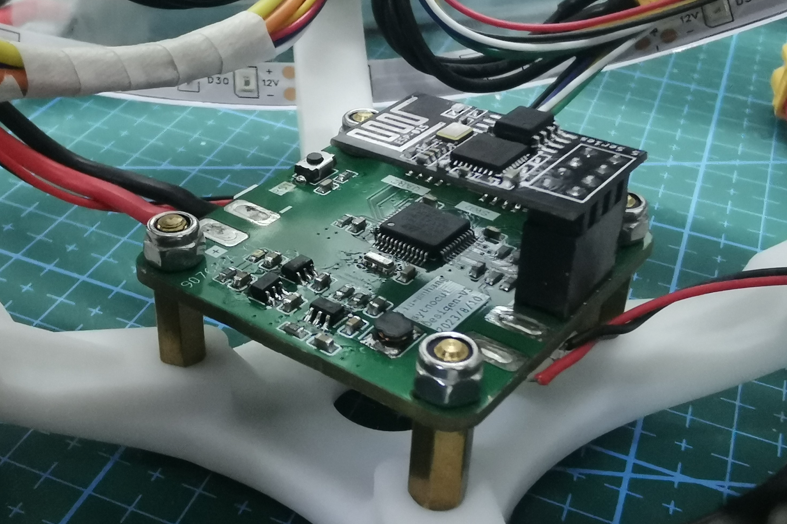
Main controller: STM32F103C8T6;
Crystal oscillator: Murata CSTCE 8M ceramic tripod crystal oscillator (same as the one used in Zhihuijun's robotic arm, no load capacitor required);
CAN communication chip: TJA1050T (note that 5V power supply is required, otherwise the microcontroller's CAN transmission and reception will freeze )
; Power management: JW5026+ME6211;
Wireless communication: classic pin-type Esp8266
; all sockets used in the wireless communication module are GH1.25 model;
all can be purchased on Taobao, the estimated cost price for a set is approximately 30 RMB (electronic component prices may vary).
Matching encoder board: ICM20602, MPU6050, ICM42688P (currently has issues, overheating severely, please use the ICM20602 module instead).
Note: The encoder board is fixed to the innermost apex of the sphere using hot melt glue, parallel to the ground.
5.2.2 Driver board:
The driver board is a four-layer board, which can be printed free of charge by JLCPCB. The driver board primarily handles the FOC speed closed-loop drive.
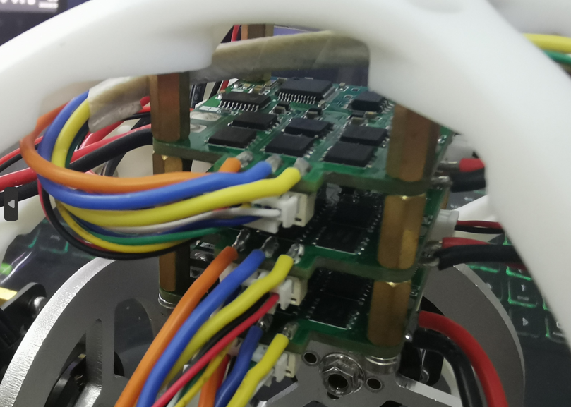
The driver board design references the Lemon FOC open-source board and is based on the GD32 microcontroller.
Reference address: [Happy New Year] Lemon FOC Open-Source Board - JLCPCB EDA Open-Source Hardware Platform (oshwhub.com).
The driver board hardware is independently designed, and the software is directly programmed with Lemon FOC code. The original open-source project allowed setting current, speed, and position closed-loop modes via PuTTY serial port assistant; however, due to project requirements, a speed step change mode was adopted here.
When using the original firmware, be sure to modify the power undervoltage protection and speed protection parameters in the serial port debugging assistant to prevent motor stoppage caused by excessively rapid speed changes.
The driver board parameters are as follows:
Main controller: GD32C103CBT6;
Crystal oscillator: Murata ceramic three-pin crystal oscillator CSTCE 8M;
CAN communication chip: SN65HVD232D
; Power management: JW5026+RT9013-3.3;
Motor driver chip: FD6288T (motor driver chip + MOSFET, high current solution);
NMOS: TPH1R403NL
; Current sampling: LMV358IPWRG4; Bias low sampling
resistor: 1206 1mR
; All connectors used are GH1.25 model;
Matching encoder: MT6816 (you need to buy one that supports SPI mode, it's easy to buy the wrong one, don't buy the wrong one).
These can all be purchased on Taobao. The estimated cost for a set is approximately 60 RMB (electronic component prices may vary).
5.3.3 BIG Handheld Terminal:
The BIG handheld terminal is a two-layer board, which can be printed free of charge by JLCPCB. The BIG handheld terminal mainly performs functions such as remotely changing control modes, safety management, real-time status display, and publishing target pose.
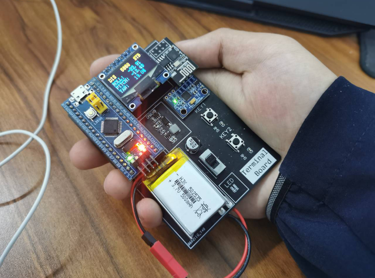
This module is modeled after Zhihui's PICO small terminal design, mainly completing some human-computer interaction functions. Because it's geared towards beginners, it looks rather rough. Since PICO means small, and Zhihui's PICO is indeed very small, but my handheld terminal is quite large, I named it BIG.
The handheld terminal parameters are as follows:
Main controller: STM32F103C8T6 sapphire core board;
Display: 7-pin OLED display, SPI mode;
Battery: 1s 300mAh lithium battery;
Gyroscope: Classic MPU6050 module;
Wireless communication: Classic pin-type Esp8266 wireless communication module.
5.3 Software Design
5.3.1 All-attitude drag effect
is implemented on the main control board. Using the Mahony attitude calculation method, the real-time roll, pitch, and yaw angles are calculated, and PID feedback control is established for each. Whenever there is an angular velocity on a certain axis, the PID algorithm generates a control output in the opposite direction on that axis. Finally, the PID control outputs of the three axes are superimposed, multiplied by the speed distribution matrix, and calculated into the speeds of the three orthogonally mounted flywheels. This output is then sent to the FOC drive board, generating a drag effect during the ball's three-degree-of-freedom full-attitude motion.
5.3.2 Three-Axis Attitude Tracking and Follow-Up:
Building upon Section 5.3.1, attitude angle feedback is added. The BIG handheld terminal collects its own attitude as the target value for the balancing ball's attitude. The difference between this target value and the actual value of the balancing ball's attitude forms the PID controller. This ultimately achieves three-axis attitude tracking and follow-up.
Because the omnidirectional wheel chassis introduces significant friction into the system, this function currently requires the ball to be placed directly on the ground, not on the omnidirectional wheel chassis.
Considering the limited effectiveness of pure PID, this project will later deploy control algorithms such as LQR for further comparative testing.
5.3.3 Playing Racing Games as a Steering Wheel
We accidentally discovered that our ball is very similar to the spherical steering wheel in The Wandering Earth. Therefore, we used a Wi-Fi module to connect to the computer, received real-time attitude information from the spherical simulator, and used the Python vGamepad library to map it to virtual Xbox game controller joystick values (steering wheel, accelerator, brake, etc.). This allows us to recognize the virtual game joystick in racing games like DiRT Rally 2.0 and obtain control data.
Because the control data is encapsulated in the form of an Xbox controller, there are no compatibility issues regardless of the racing game played.

5.4 Concept Design (Fun)
The ball can be transformed into many interesting things by adding outer decorations. For example,
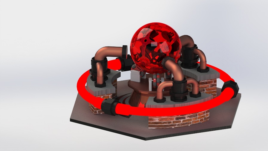


anything round can be used to capitalize on a trend.
6. Precautions
6.1 Software Description
This project provides firmware code for the main control board and BIG handheld terminal. The firmware of the driver board is completely consistent with Lemon FOC. Please refer to the Lemon FOC project for burning and use:
Reference link: [Happy New Year] Lemon FOC Open Source Board - JLCPCB EDA Open Source Hardware Platform (oshwhub.com)
All microcontroller firmware in this project is developed using Clion. If you are unfamiliar with Clion project configuration, it is recommended to watch Zhihui's Clion+STM32 Environment Configuration Guide:
Reference link: Configuring CLion for STM32 Development [Elegant Embedded Development] - Zhihu (zhihu.com)
6.2 Motor Selection
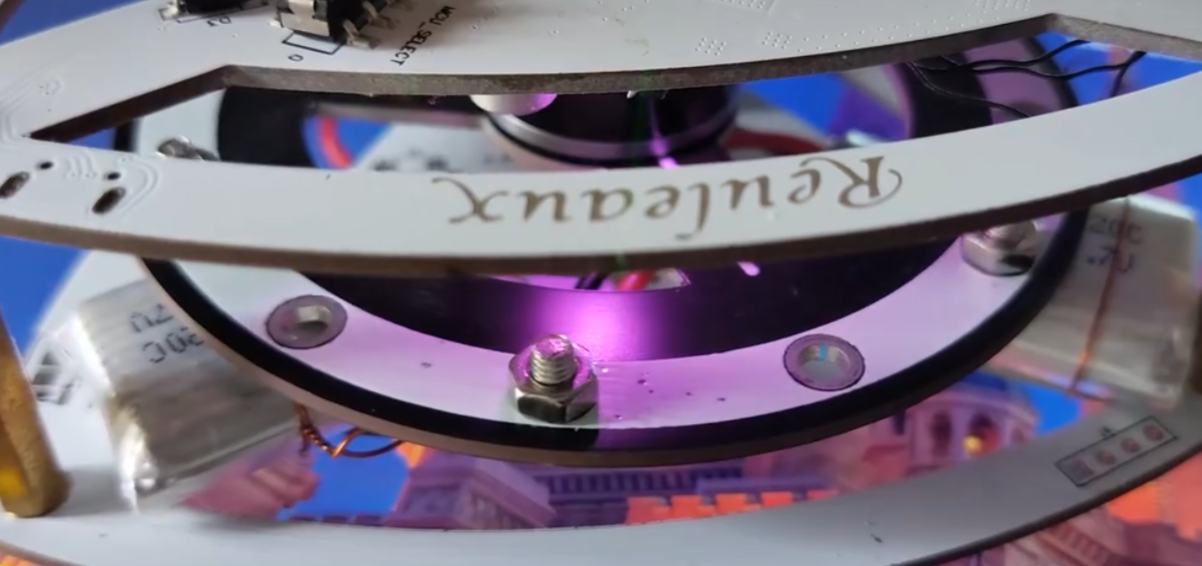
The selection of flywheel and brushless motor is very important. Due to the high friction of the entire system, the low-kV gimbal motors used in the common Reilly triangle and balance cube in the open source community are difficult to meet the torque requirements. I accidentally found this motor on Taobao's second-hand motor section:
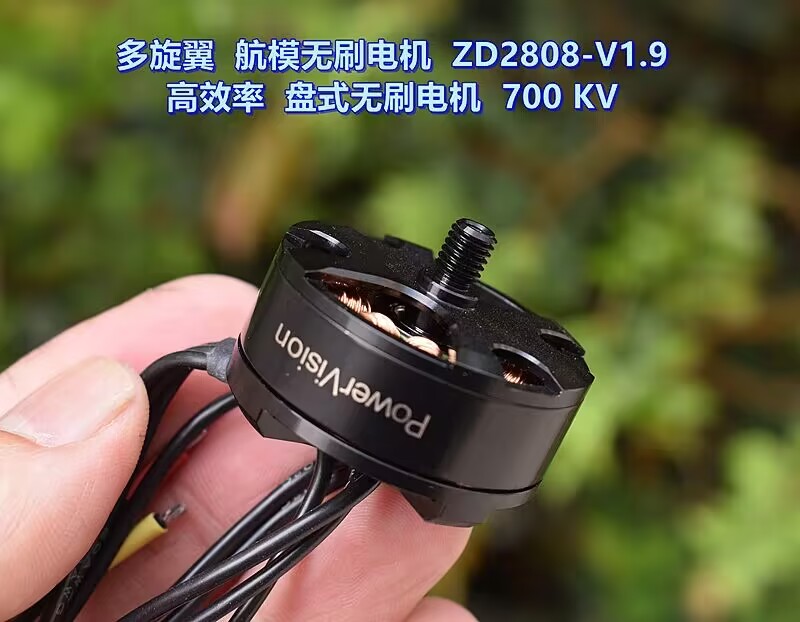
After testing, the load capacity of this motor is very suitable for this project, the cost is low (only 16 yuan), and it saves space. Considering that these used motors are often sold out quickly, if they become unavailable, a DJI 2312 Phantom motor could be considered as a replacement.
Additionally, if the aluminum alloy flywheel provides insufficient reaction torque, a solution similar to this open-source project could be used to create a custom flywheel and drill holes in the outer edge to install bolts, increasing the flywheel's moment of inertia.
Reference: Self-balancing Reilly triangle based on LQR controller (Bilibili
). Regarding gyroscope selection,
the gyroscope board used in this project is the ICM42688P. However, different batches of ICM42688P purchased from Taobao all exhibited problems such as severe overheating (approximately 60 degrees Celsius) and significant temperature drift, although they could read the correct data. It has been confirmed that the issue is not a soldering problem; it is currently unknown whether it is a material problem or a hardware design issue. It is recommended to carefully consider purchasing ICM42688P from Taobao. This project temporarily uses the ICM20602 module from Zhufei Technology as the gyroscope board.
This project currently uses the ICM20602 module borrowed from the community, and the main control board also supports the MPU6050 connector. The driver code for all three gyroscopes is in the project, but the interface code needs to be modified manually.
7. Project Progress (
First Open Source, August 30, 2023)
: Completed parts:
All structural and hardware design and construction are complete; the structural and hardware design is mature and convergent.
All logic code is written.
Basic control algorithms are written, enabling basic angular velocity and attitude closed-loop control.
Future plans:
Due to the complexity of the control system, the attitude closed-loop control code needs optimization. Key measures include:
adding counterweights to bring the center of gravity closer to the spherical center and ensuring consistent inertia across the three axes.
PID control is insufficient; a model-based control algorithm will be used, such as modeling friction
parameters based on Euler equations and LQR, and compensating using a disturbance observer (ADRC algorithm can also be used).
Quaternion-based attitude closed-loop control will be attempted to eliminate Euler angle deadlock.
Project members are independently developing FOC driver code based on STM32F103C8T6. Upon completion, this will replace the current driver board based on GD32 developed by Lemon's FOC team.
A host computer software based on Qt and OpenGL will be developed to provide real-time attitude visualization and remote parameter tuning; the results can be referenced from Zhihui's electronic robot and various flight control debugging assistants.
An embedded shell will be implemented to support remote parameter tuning via Wi-Fi serial port .
Shock-absorbing pads will be added to the gyroscope to prevent high-frequency vibrations from the motor from interfering with it.
Problems with the ICM42688P will be identified, and the currently used ICM20602 will be replaced.
8. Material Specifications
: Structural Components Bill of Materials:
Material
Purpose
, Required Quantity,
Purchase Link:
Sphere Main Structure,
Acrylic Sphere Shell, 20mm,
Transparent Sphere Shell
>= 2
https://m.tb.cn/h.54hODsa?tk=Q7ZXdzW9Ydo
3D Printing (Internal Support Frame - Connection Points)
Cross-shaped Main Frame
6
JLCPCB 3D Monkey
3D Printing (Internal Support Frame - Bridging Points)
Connection Points of Main Frame
8
JLCPCB 3D Monkey
3D Printing (Bracket - Battery Small)
Fixing Battery
1
JLCPCB 3D Monkey
Brushless Motor Related
Disc Brushless Motor ZD2808-V1.9
3
https://m.tb.cn/h.5WJTsy4?tk=4qczdC51605
Aluminum Alloy Flywheel 6mm 80mm
3
https://m.tb.cn/h.5e1xS1N?tk=HlGCdC6gCA1
Radial Magnet 6*2.5
Obtain Motor Shaft Position
3
https://m.tb.cn/h.54hiYKJ?tk=QM5mdzWTh2m
3M Super Glue
Fixes Magnet to Motor Shaft
1
https://m.tb.cn/h.54AlcCb?tk=jlEVdzWQEFG
Ball Main Body Accessories:
M3*8 cup head screws (
main structure fixing screws,
several);
M3 anti-loosening nuts
(main structure fixing nuts
, several);
Copper pillars: M3*10+6
(main support copper pillars
, 20) ; M355 embedded
nuts (connecting the ball shell
to the 3D printed parts,
2)
; M3*8 countersunk screws ( connecting the ball
shell to the 3D printed parts,
2)
; Counterweights (
balancing center of gravity position,
several).
https://m.tb.cn/h.56VXPSI?tk=n4DUWYhMTac
Circuit Part : Main
Control Board
1 (JLCIC free PCB, components self-processed); FOC Driver Board 3 (JLCIC free PCB, components self-processed); Encoder Board 3 (JLCIC free PCB , components self-processed ); Gyroscope Board (optional) 1 (JLCIC free PCB, components self-processed) ; BIG Handheld Terminal 1 (JLCIC free PCB, components self-processed); WiFi Module ( ball and BIG, ball and PC communication) 3 https://m.tb.cn/h.56vZKps?tk=XmldWYhGjPn USB to serial converter module for connecting WiFi module to computer, sphere and PC communication 1 https://m.tb.cn/h.56vZKps?tk=XmldWYhGjPn Model aircraft battery 3s 550mAh 85C power supply >= 1 https://m.tb.cn/h.5fuIsF0?tk=Pxn2dzWQvsg Cables: Silicone wire 18AWG , power cable (several), Silicone wire 20AWG , motor wire (several), GH1.25 6p double-headed reverse 30cm encoder cable 3, GH1.25 6p double-headed reverse 30cm gyroscope cable 1 , GH1.25 2p double-headed reverse 15cm CAN bus 4 XT30 head connects to battery 1. Chassis acrylic cutting (chassis - upper layer) Chassis main body 1. Find acrylic cutting 3D printing on Taobao (omnidirectional wheel axle seat - key) Supporting omnidirectional wheel 3. JLCPCB 3D Monkey 3D printing (omnidirectional wheel axle seat - round) Supporting omnidirectional wheel 3. JLCPCB 3D Monkey 3D printing (omnidirectional wheel support leg - split type) Supporting omnidirectional wheel 6. JLCPCB 3D Monkey F car model omnidirectional wheel support acrylic spherical shell 3. https://m.tb.cn/h.5Vqiebu?tk=y4CAdzW76o4 Bearing 7*1 1*3 Connecting omnidirectional wheel and optical axis 6. https://m.tb.cn/h.54hQEqA?tk=cFWBdzW7L1a Optical axis cutting (omnidirectional wheel optical axis) Supporting omnidirectional wheel, note the slotting 3. https://m.tb.cn/h.5fuKVfU?tk=G4sGdzW7mtl 12 M4*55 screws for securing omnidirectional wheel axle seats; 12 M4 anti-loosening nuts for securing omnidirectional wheel axle seats; optional feet; several anti-slip bases . https://m.tb.cn/h.54AknHL?tk=cSfIdzWjeUe
The total price is around 800-1000 yuan. The price of some parts may vary greatly, so please refer to the actual situation.


 京公网安备 11010802033920号

 232-104-00NF16-26SB-02


