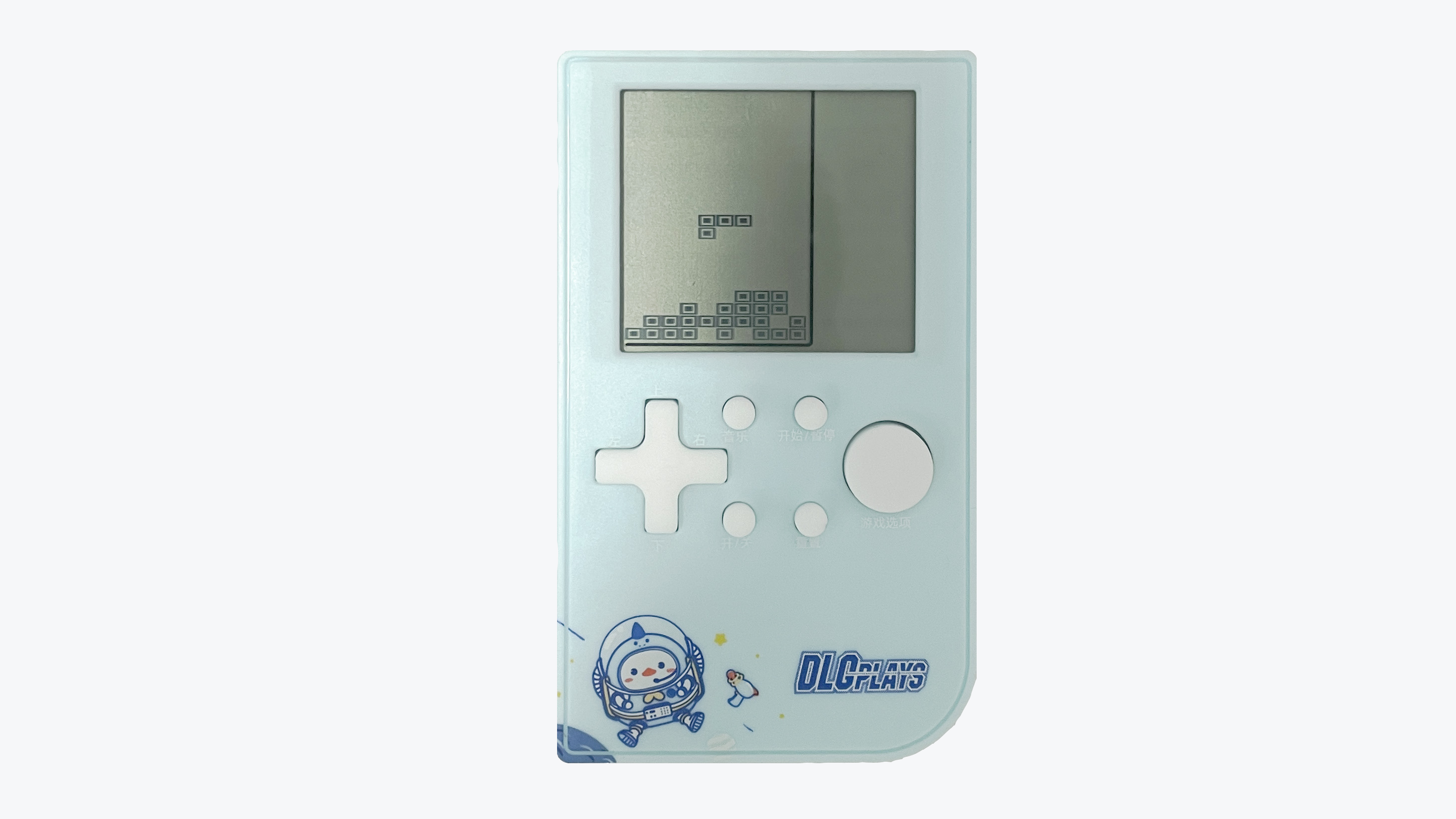
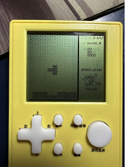
The game console shown in the picture below is familiar to many born in the 80s and 90s. In the era before widespread mobile phones, these inexpensive game consoles brought joy to many children's childhoods.
Classic games like Tetris and Battle City are deeply ingrained in the memories of a generation.
When I was an undergraduate, after finishing my studies in microcontrollers and displays, I really wanted to make a game. I remember using a Nokia 5110 screen and even finishing half of it before my lab supervisor criticized me for neglecting my studies, so I abandoned it.
I've always believed that game programming involves far more logic than ordinary projects, and learning microcontrollers through game projects can better train students' thinking and cultivate their interest in learning. So, after starting work, I restarted this project, hoping to provide a platform for electronics enthusiasts to create small games.
The project uses a 51 microcontroller as the main control chip and borrows the original game console's casing, screen, buttons, and speaker to implement the Tetris functionality. In addition, the power system of the original game console was upgraded to a lithium battery with a Type-C charging interface, making it more in line with modern usage habits. The biggest highlight of this project is the use of the original game's screen, enabling the development of an authentic game experience. The core components of the entire product are shown in the image below.

This product might be a bit childish for elementary school students, but it's perfect for university students.
It can serve as an everyday toy for electronics enthusiasts, as well as a game development device, helping to cultivate basic game development thinking and increasing beginners' interest in electronics and programming.
Bilibili Video Link: https://www.bilibili.com/video/BV1jo4y1776f
I. Basic Information
1.1 Core Parameters
Main Control Chip: STC8H8K64
Operating Frequency: 30 MHz
Flash Size: 64KB
RAM Size: 8KB
Screen Resolution: 10 * 20
Number of Buttons: 9
Battery Capacity: 400 mAh
Charging Interface: Type-C
PCB Layers: 2
PCB Size: 7.04cm * 5.71cm
Charging Voltage: 5V
Number of Games: 1 (Custom games can be developed)
1.2 Cost Budget
Original Game Console: ¥8.3
STC8H8K64: ¥3
CH340N: ¥1.5
Battery: ¥4
PCB & SMT: ¥10
II. Operation Instructions
2.1 Development Method
Integrated Development Environment: Keil5
Programming Language: C
Programming Software: STC-ISP
Programming Tool: Onboard USB to Serial Port
2.2 The device is programmed
using STC-ISP, the programming software provided by STC. The latest version of the programming software can be downloaded from the STC official website. The programming configuration parameters are shown in the following figure:
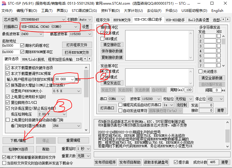
The game console's power on and off are achieved through a combination of hardware and software. In the power-off state, press and hold the power button for 1 second to power on the device. In the power-on state, lightly touch the power button to power off.
When programming the firmware, the above parameters must be configured first. Power off the game console, click the [Download/Programming] button, and press and hold the power button until programming is complete.
2.3 Operation Instructions

In the power-off state, press and hold the power button for 2 seconds to power on. After powering on, you will enter the Tetris game interface.
Left and right arrow keys: Control the block to move left and right.
Up arrow key: Pause the game.
Down arrow key: Accelerate the block's descent to the bottom.
Large circle key: Rotate the block
. In the power-on state, lightly touch the power button to power off.
The power button on the device is fixed, while the functions of other buttons can be customized by modifying the code.
III. Production Process
3.1 Game Console Selection
First, several similar game consoles were purchased, and this model suitable for modification was selected.

Then, it was disassembled to analyze its working principle. These game consoles almost all use dedicated chip chips, making it difficult to obtain information from the chip itself.

3.2 Drive Principle Analysis
By measuring the signals on the circuit board with instruments, it can be found that the buttons change between high and low levels, and the buzzer is a PWM signal. These are relatively simple to analyze.
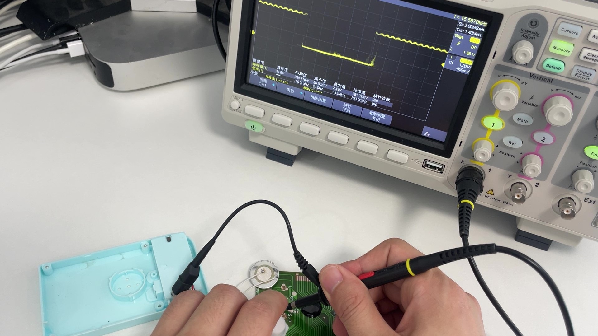
The complex part is the LCD screen drive signal. This type of screen mostly uses multi-level scanning drive, and there is relatively little relevant information online, so it has to be explored little by little. Using an oscilloscope to observe the waveforms of the 36 CD drive pins, it can be found that their level forms are roughly divided into two categories. One type is the waveform signal shown in the figure, which is very regular, with four level segments: VCC, three-quarters VCC, one-quarter VCC, and GND. The other type is a relatively irregular waveform signal, with three level segments: VCC, half VCC, and GND.

Based on scattered information found online, the regular signal is from the COM pin, and the irregular signal is from the SEG pin. Simply put, the COM pin controls which column the screen is currently scanning, and the SEG pin controls which row.
3.3 Implementation of the LCD Driver Circuit
Having clarified the LCD driver model, the next challenge is how to generate such signals using microcontroller pins. Ordinary microcontroller pins only have high and low voltage levels. To generate the above signals, a resistor divider can be used.

For the SEG signal, only one microcontroller pin and two 10K resistors are needed, as shown in the figure. When microcontroller pin A outputs a low level, the voltage at the SEG terminal is GND; when the microcontroller pin is floating, the voltage at the SEG terminal is half VCC; and when microcontroller pin A outputs a high level, the voltage at the SEG terminal is VCC.
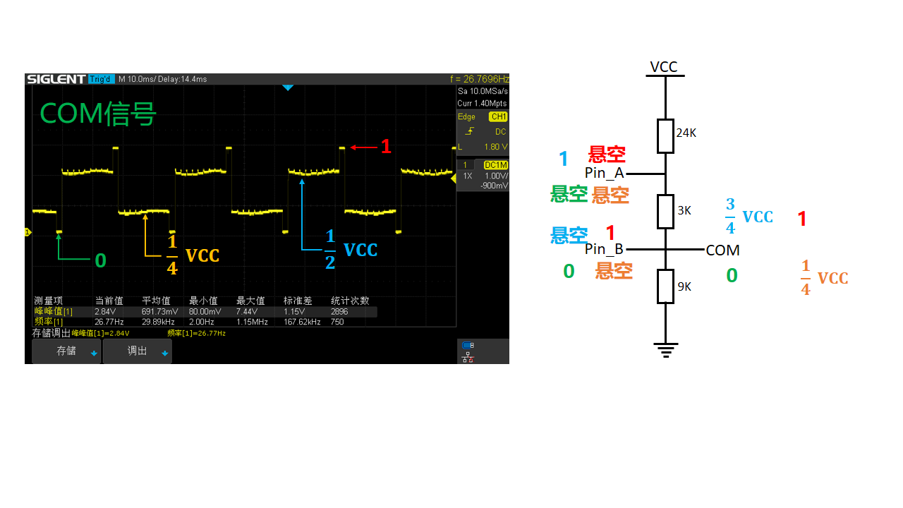
The implementation of the COM signal is slightly more complex, requiring two microcontroller pins and three resistors, as shown in the figure. The resistor values are 9K, 3K, and 24K respectively. When pin A of the microcontroller is floating and pin B outputs a low level, the voltage at the COM terminal is GND. When both pins A and B are floating, the voltage at the COM terminal is one-quarter VCC. When pin B is floating and pin A outputs a high level, the voltage at the COM terminal is three-quarters VCC. When pin A is floating and pin B outputs a high level, the voltage at the COM terminal is VCC.
3.4 Schematic Design
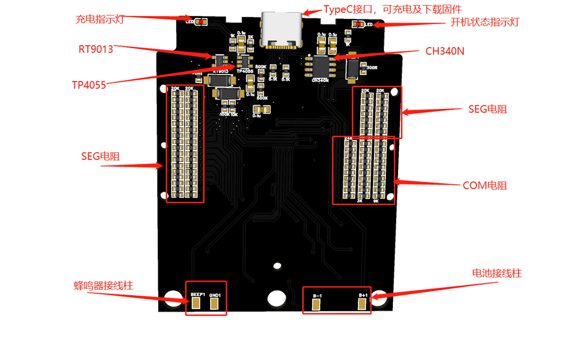
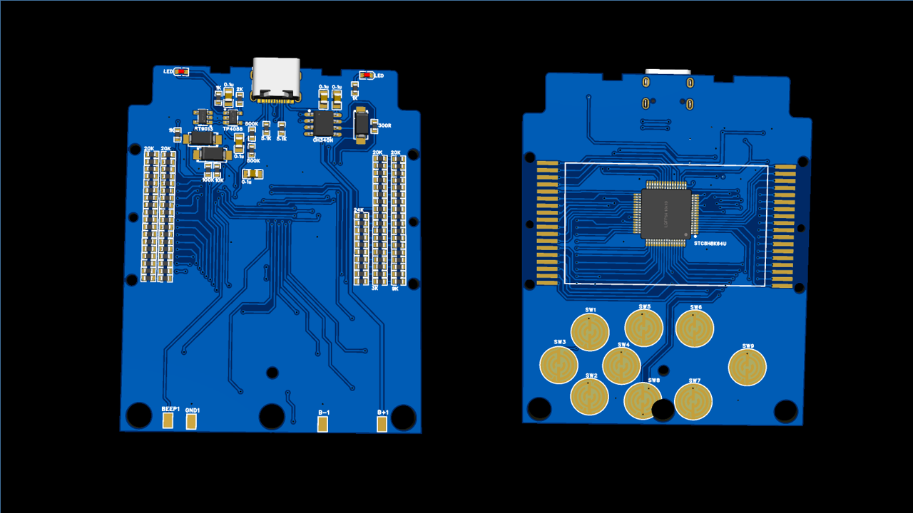
With the above theoretical foundation, the circuit diagram can now be designed. The LCD screen has a total of 10 COM pins and 26 SEG pins, so driving the LCD using the above method requires a total of 46 microcontroller pins. This project uses the LQFP packaged 51 microcontroller STC8H8K64, which has 60 usable I/O ports, perfectly meeting the project's requirements. The LCD driver circuit uses a large resistor network. Additionally, USB-to-serial port, lithium battery charging, and one-button power on/off circuits are added to the entire system.

The schematic diagram PDF and source files can be downloaded from the attachment!
3.5 PCB Design
After completing the schematic design, remove the original game console's circuit board, measure the outer frame dimensions, screw holes, and button positions to determine the shape of the PCB we need to design.

The wiring is relatively simple, basically just manual labor. The completed PCB rendering is shown below:
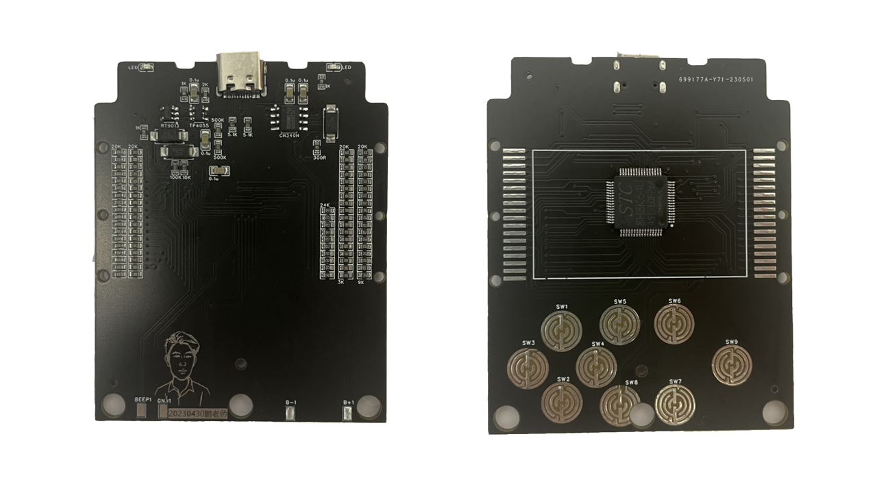
After the PCB design is complete, order a sample from JLCPCB and perform STM surface mount technology (SMT). To save costs, I only mounted the components from JLCPCB's basic library; the remaining components were hand-soldered. The following image shows the front and back of the soldered PCB:
3.6 LCD Driver Design
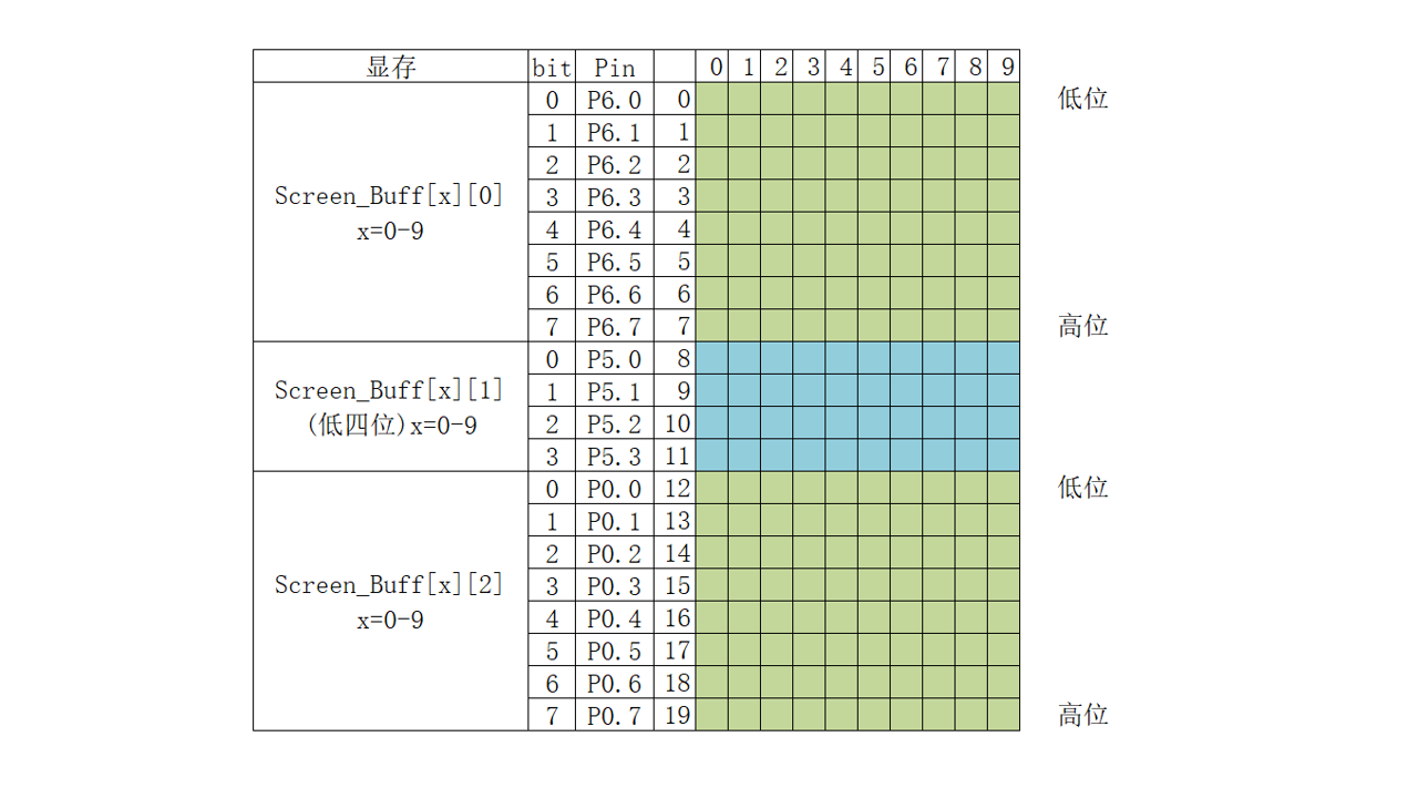
First, the LCD driver uses a timer to scan a COM pin every 2ms, simultaneously placing the data to be displayed on the SEG pin. Scanning all 10 COM pins takes 20ms, so the screen refresh rate is 50Hz.
3.7 Buzzer Driver Design
A timer is used in conjunction with GPIO pins to generate a square wave to drive the buzzer. First, calculate the timer parameters based on the frequency of the notes to be played, store them in an array, and then define the music data format.

This project includes 16 built-in pitches and 16 time values. Each note in the music data is represented by one byte, for example, 0x47. The high four bits (4) represent a pitch of 587Hz (middle 2), and the low four bits (7) represent a time value of (7 + 1) * 16th note, i.e., a half note.
3.8 Tetris Game Design
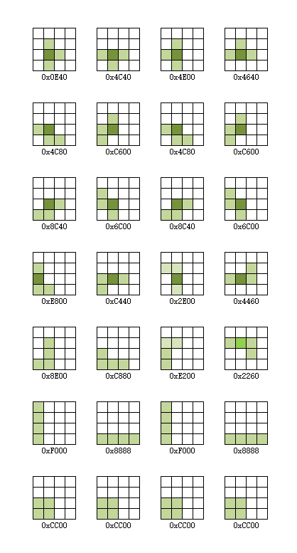
After the driver is completed, the game can be written. Due to time constraints, I only implemented the Tetris game here. The specific implementation process is as follows: first, the blocks appearing in the game are classified, and each block and its rotation and mirror image are converted into binary data. Then, the program uses a timer to control the block's fall, while simultaneously handling the block's rotation and left/right movement. Finally, when the block falls to the bottom, it is checked for a complete row. If there is, it is eliminated, and the next block is randomly generated, repeating the cycle.
Detailed code can be found in the attachment!
Actually, the game logic is much more complex than many programs. Trying to independently implement a game is very helpful for improving programming thinking. Back when I was in school, I tried to implement a Tetris game. My teacher criticized me for neglecting my studies, and the project was abandoned. Now, I've continued that work and completed the game using the relatively simple 51 microcontroller. My hope is to spark students' interest in electronics and programming. I encourage them to try implementing games like Tank Battle or Snake, based on my design. I believe this will greatly benefit their development.
Fourth, thanks
to Bilibili user @hlken for completing the music switch, scoring, and other functions. The source code link is as follows:
Link: https://pan.baidu.com/s/1oVaQtoZxQhK4F29QlXsz2g?pwd=264s Extraction code: 264s
Thanks to Bilibili user @江上清风灬 for completing the Snake game.


 京公网安备 11010802033920号

 XLT2419-07AC


