The core working principle of a Geiger tube:
A Geiger counter is a counting instrument specifically used to detect the intensity of ionizing radiation and is still widely used in nuclear physics and particle physics experiments. Since its prototype appeared in 1928, and despite numerous improvements and significantly increased sensitivity, its working principle remains unchanged.
A Geiger tube consists of a metal wire, electrodes on both sides, and a glass shell. The metal wire is considered the positive electrode, and the metal coating on the outer layer of the glass shell is considered the negative electrode. The inside of the glass tube is filled with an inert gas, such as helium, neon, or argon. During operation, a relatively high voltage is applied to the positive electrode, slightly lower than the breakdown voltage of the internal inert gas. Under normal circumstances, the gas inside the tube will not discharge. However, when high-speed X-ray particles enter the metal tube, the high-speed particles can ionize the low-pressure gas inside, causing the gas to break down and resulting in a rapid discharge and the output of a pulse current signal. By detecting and counting this pulse signal, and combining it with functions such as screen display and a buzzer, the measurement of X-ray particles, i.e., the intensity of radiation, can be visually reflected. The normal operating voltage of a Geiger transistor is generally around 400V, which cannot be provided by a typical external power supply or battery. Therefore, the core of
implementing
a Geiger counter is to design a reasonable, low-power boost circuit. The principle mainly utilizes an inductor with accepting and rejecting properties, combined with a PWM charging/discharging signal with a specific duty cycle, to continuously charge the capacitor, thereby achieving the effect of a continuously increasing capacitor voltage. There are many ways to generate PWM signals; a dedicated PWM chip, a timer like the NE555, or a direct implementation by an MCU like the ESP32 can be used.
We chose to try a solution that directly uses the MCU to generate PWM
(using a PWM capable pin for PWM signal transmission) .
The overall circuit includes the following modules:
1. Boost circuit
2. Pulse detection and shaping
3. MCU and button control
4. External power supply and charging circuit
5. Screen and I2S circuit.
1. Boost Circuit:
Since the on-state voltage of the N MOSFET IRFP450 we selected is 4V, while the I/O voltage of our MCU module is 3.3V, the PWM signal generated by the MCU needs to be amplified to a sufficient voltage to fully turn on the MOSFET. Ultimately, we chose the EG3001 as the driver chip. The circuit can boost the voltage normally when VCC is 5V. When selecting a MOSFET, please choose a model with strong voltage withstand capability.
2. Pulse Detection:
When high-speed X-ray particles enter the Geiger tube, the high-speed particles can cause ionization of the low-pressure gas inside the tube, leading to gas breakdown and rapid discharge, resulting in an output pulse current signal. The count of the pulse signal, i.e., cpm, is calculated/adjusted and displayed on the screen, or combined with functions such as a buzzer, to intuitively reflect the measurement of X-ray particles, i.e., the intensity of radiation. Here, we use IO14 as the pulse signal monitoring port.
3. MCU and Display:
We designed a pluggable MCU module with reserved encoder, buttons, I2S, and screen. This allows it to be plugged into the Geiger counter board or other modules, and supports development and experimentation with other MCU solutions such as STM32/CM32. Meanwhile, since the board has a reserved I2S circuit to replace the buzzer, it can support playing various sounds for audio alerts.
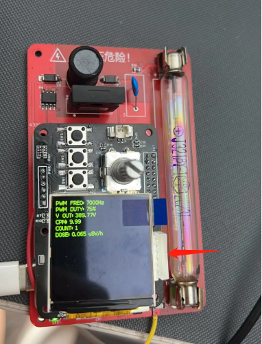
By adjusting the encoder, you can see the voltage under different duty cycles and the number of Geiger tube breakdowns. Our current PWM frequency is set to 7kHz. After reducing the PWM duty cycle from 75% to 50%, the voltage drops to 250V, which is lower than the minimum operating voltage of the Geiger tube, and the CPM value drops directly to 0. In actual use, since the 7kHz frequency is audible to the human ear, you will hear a faint buzzing sound. If you don't want to hear it, you can replace the inductor and capacitor to find a suitable PWM frequency. The software
source code for converting the number of Geiger tube breakdowns (CPM) to the radiation dose (µSv)
mainly consists of three parts:
1. PWM initialization, output, and voltage measurement.
2. Pulse counting and calculation.
3. Numerical display.
The main part to learn and understand is the second part—pulse counting and calculation.
As we know from the principle of the Geiger tube, when the Geiger tube detects the presence of ionizing radiation particles, the inert gas inside is broken down, generating a pulse signal, which is also the number of breakdowns. The basic counting parameter of the Geiger counter is the number of breakdowns per minute, or CPM. The more particles, the higher the CPM, and the greater the radiation dose. However, in various news reports, professional literature, or popular science articles, the unit of measurement we usually see is radiation dose units like uSv/h. Therefore, the core problem of software implementation is how to convert the CPM count value into radiation dose data that we are more familiar with.
In fact, each Geiger tube is provided with a conversion factor at the factory, which is used to convert CPM into radiation dose. The conversion factor is usually calibrated in the laboratory using Co-60 or Cs-137, etc. The value of this conversion factor is usually an approximate value, and different laboratory conditions and the use of radioactive isotopes will affect the final result.
For example, the conversion factor of the J321/M4011 we used this time is 153.8 CPM = 1 uSv/h. If we cannot find the conversion factor for a particular tube, we recommend using the tube's background CPM value divided by the background radiation dose in its country of origin. For example, if the median average radiation intensity in my country is approximately 0.15 uSv/h, and the tube is manufactured domestically with a background value of 20, then the approximate final CPM would be 151, i.e., 151 CPM = 1 uSv/h. (x = 1/0.15 * 20 = 151). More detailed radiation-related information can be found on the official website of the National Nuclear Safety Administration.
Software source code acquisition:
Link: https://pan.baidu.com/s/1O0tMuas3zKmRBC1w5OWfMg?pwd=mokm
Recommended software programming tool: Visual Studio Code.
After successful compilation, the program needs to be burned to the MCU module board. Burning port location:
A few final tips:
1) The β and γ rays detected by the Geiger tube can be blocked by aluminum foil, plexiglass, or metal. Therefore, when customizing the casing in a DIY solution, it is recommended to allow the Geiger tube to have more contact with air and not completely block it. If you buy a ready-made product, you don't need to worry about this for now.
2) The Geiger tube has a limited lifespan, which is shorter than that of other components in the counter. Generally, when we purchase a Geiger tube, the technical parameters will indicate its lifespan, which is listed as 1*10^9 pulses, meaning it will likely need to be scrapped or returned for major repairs after 1 billion pulses.
3) The Geiger counter has sensitivity. Professional-grade counters are not only very expensive (4 figures/USD) but also require regular calibration. Most importantly, the preconditions for measuring radioactive elements are quite complex, and it is generally difficult to achieve truly accurate radioactivity monitoring using a single monitoring method or instrument. Therefore, it is essentially a small toy and should not be relied upon excessively.
4) When using a counter near the bathroom or marble products, the test results are generally surprisingly good.
(Updated 2023/09/05)
Small clips for leather tube clamps can be found on Taobao by searching keywords such as "fuse clamp," "fuse tube clamp," or "fuse tube holder." A 6*30mm size is ideal.


 京公网安备 11010802033920号

 1.5KE16C


