Project Introduction:
This project is primarily for learning software development for keyboard devices, covering commonly used keyboard components and serving as a reference for hardware design to some extent. Since it's for software development learning, you can choose your own development framework. I've chosen Rust, using the default framework from the official STM32F4 template.
Important!!!
I'm also a beginner, so many of my understandings may not be correct or accurate. Please forgive any errors or omissions.
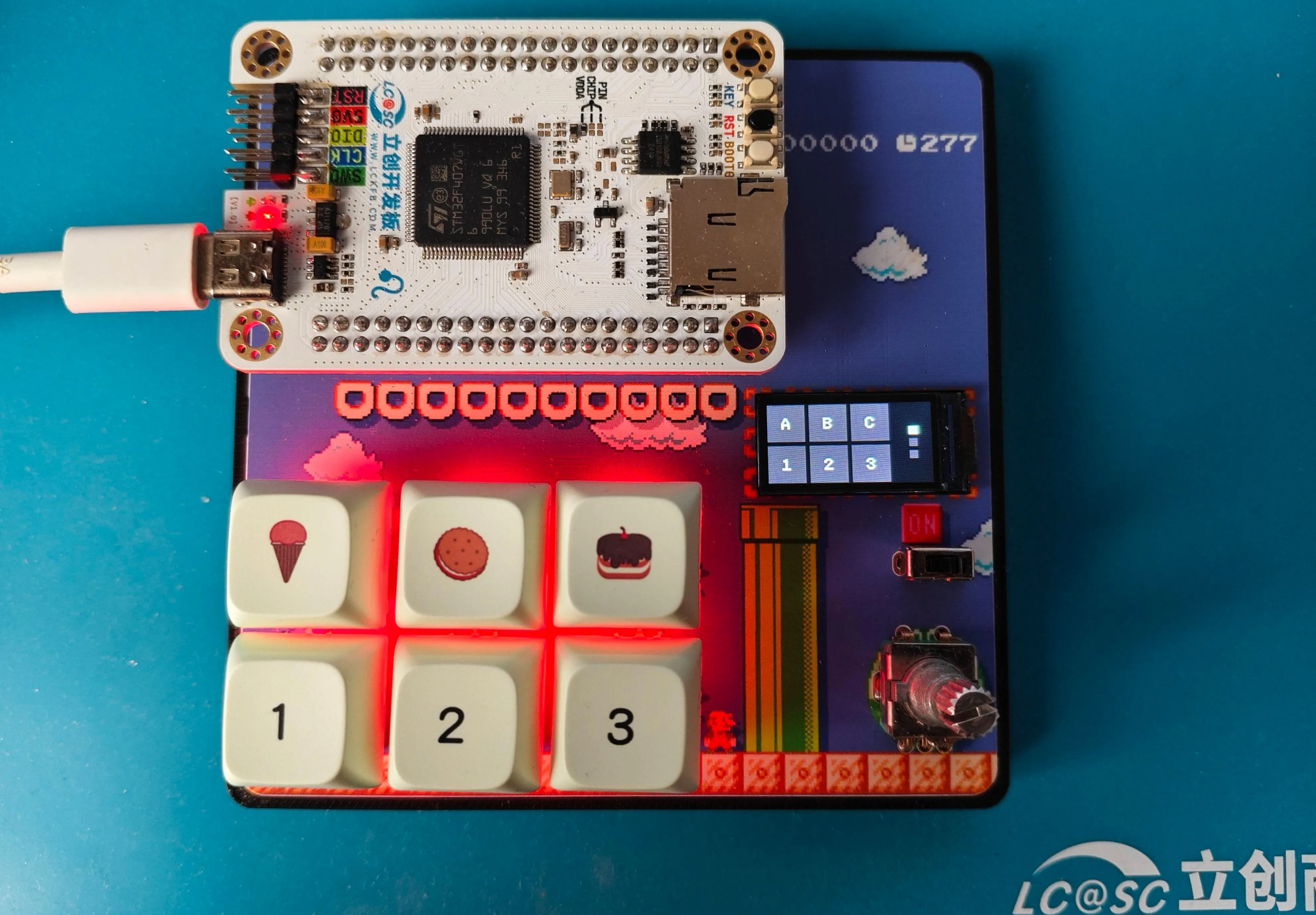
Component Introduction:
Kailh hot-swappable switches
. Standard switches, compatible with most mechanical switches on the market. You can design your own package or use open-source packages designed by others on the LCSC community. Mainly divided into those with and without LED holes. Search for
"ws2812b 3528/6028 reverse-mount RGB LEDs"
for mechanical keyboards. There are various keyboard designs using
the 74HC165 shift register
, the most common being the matrix keyboard design. You can search for more information if you're interested. Here, I'm using a shift register solution, essentially expanding the GPIO to correspond one-to-one with the key switches. However, since it's not a true GPIO expansion, each pin needs a pull-up or pull-down resistor to ensure the level reverses when the switch is closed. For example, I connected a pull-up resistor, and grounded the other end of the key switch. This means the shift register returns high by default and low when pressed, thus determining if the key switch is pressed .
The AI32C touch chip is a 3-channel touch chip. The corresponding "pipe" on the PCB
isn't commonly found in finished mechanical keyboards, but it's present in many open-source mechanical keyboards, so I included it, and the output is connected to the shift register. Many finished keyboards now have rotary knobs, mainly using potentiometers and rotary encoders. A few open-source keyboards use motors (which are more expensive). Here, I've chosen the common EC11 rotary encoder. More and more keyboards are adding displays, although their practicality is low, they offer a lot of fun. Toggle switches are something that most keyboards have, and they are usually used to control the power supply or platform selection (Win and Mac) or the connection method selection (2.4, USB, BLE). The corresponding pins for the components are WS2812B 3528/6028 reverse-mounted RGB LED beads. DIN <=> C07 is a common GPIO pin for single-wire control. There is also a type that is controlled via SPI, which I haven't figured out yet. 74HC165 Shift Register Q7 <=> B04/SPI1_MISO Data Output Interface (wiring compatible with SPI control, but I'm using the normal control method and haven't yet looked into how SPI controls the shift register). PL# <=> B05 Load Pin CP <=> A05/SPI1_CLK Clock Pin CE# <=> D06 Enable Pin; in actual development, a pull-down resistor can be directly connected. D0 <=> K1 Button 1 D1 <=> K2 D2 <=> K3 D3 <=> K4 D4 <=> K5 D5 <=> K6 D6 <=> OUT1 Corresponds to the OUT1 output of the touch chip D7 <=> OUT2 Corresponds to the OUT2 output of the touch chip DS <=> _ In actual development, multiple shift registers will be used, connected together through this pin. AI32C Touch Chip KEY1 <=> 1 First segment of the three-segment filled area KEY2 <=> 2 KEY3 <=> 3 EC11 Rotary Encoder D <=> C12 EC11 push button switch A <=> C11 EC11 A pin B <=> C13 EC11 B pin 0.96-inch LCD full-color display SDA <=> C03/SPI2_MOSI SPI input SCL <=> B10/SPI2_CLK SPI clock RS/DC <=> D02 Data command selection RES <=> C08 Reset CS <=> B09/SPI2_CS Chip select LEDK <=> D03 Backlight toggle switch <=> C09 Software example ... indicates that other code is omitted. The complete code will be placed in the attachment at the bottom. Scanning buttons // The basic logic is to configure the corresponding GPIO and then read the data according to the requirements of the shift register let p = pac::Peripherals::take().unwrap(); ... let gpioa = p.GPIOA.split(); let gpiob = p.GPIOB.split(); let gpiod = p.GPIOD.split(); ... let q7 = gpiob.pb4.into_input(); let mut scan_cp = gpioa.pa5.into_push_pull_output(); let mut scan_pl = gpiob.pb5.into_push_pull_output_in_state(PinState::High); let mut scan_ce = gpiod.pd6.into_push_pull_output(); ... let mut scan_timer = p.TIM1.counter_us(&clocks); scan_timer.start(2.millis()).unwrap(); ... loop { if scan_timer.wait().is_ok() { scan_pl.set_low(); scan_pl.set_high(); let mut temp_data: [u8; 8] = [0; 8];
for i in 0..8 {
if q7.is_high() {
temp_data[i] = 1;
} else {
temp_data[i] = 0;
}
scan_cp.set_high();
scan_cp.set_low();
}
}
...
}
ws2812b (I mainly implemented a three-color cyclic breathing)
// This involved quite a few pitfalls, because the ws2812b is a single-pin communication, where the low level requires a delay of about ~200ns
// I naturally used the framework's delay_ns(200)
// However, it didn't work
// After trying and searching for a long time, I found that the delay_ns method couldn't achieve that precision
// Finally, referring to some C projects using an empty loop a specified number of times, there was also a small pitfall: you can't use cargo run
// You need to use cargo run --release, otherwise the time will still exceed the limit and cause it to have no effect
// The logic of the breathing light is to convert the RGB value to a format such as HSV, then adjust the brightness and convert it back to RGB format .
// I didn't implement the conversion logic myself, I directly used a third-party library to handle it
...
pub fn set_color(
pin: &mut LedPin,
delay: &mut Delay,
rgb_color: (u8, u8, u8),
) -> Result<(), u32>
where
Delay: DelayNs,
LedPin: OutputPin,
{
let grb_color = [rgb_color.1, rgb_color.0, rgb_color.2];
for c in grb_color {
for i in 0..8 {
let mask = 0x80 >> i;
if c & mask != 0 {
pin_high(pin)?;
delay.delay_us(1);
pin_low(pin)?;
delay_250ns();
} else {
pin_high(pin)?;
delay_250ns();
pin_low(pin)?;
delay.delay_us(1);
}
}
}
Ok(())
}
...
// Part of the breathing light code
let current_color = self.colors[self.current_color_index as usize];
let current_color_u8: Srgb = current_color
.darken(self.dark_percent as f32 / 100.0)
.into_format();
Considering the length, I won't paste all the code here (my code is also average, if needed, please download the complete code in the attachment and check it yourself). The rest mainly discusses the idea of
the touch part
// First, polling every 2 milliseconds, then determining if there is a previous touch, if not, recording the current touch key
// If there is a record, then determining the sliding direction based on the current value
// My implementation requires Key1 and Key3 to slide to each other's positions, Key2 supports single click.
EC11 rotary encoder
// There are many documents on rotary encoder control itself, so I won't go into detail
// I mainly want to talk about the pitfalls I encountered when using rotary encoder to control volume
// If it is only used as an HID Sending VolumeUp or VolumeDown to the KeyBoard device has no effect (maybe there's some other setting I don't know about).
// The solution is to add another Consumer device.
Finally
, I don't know what else to say. Happy National Day in advance!


 京公网安备 11010802033920号

 1RGS372-636GG


