I. Introduction
This design was inspired by: https://oshwhub.com/kirito/rtl8367-4ge-2sfp_copy
To minimize the board size, this design uses a large number of 0402 resistors and capacitors. If you are not confident in your soldering skills, it is recommended to use a stencil for soldering. It is suggested to find a vendor on Taobao; a small stencil can be obtained for around 20 RMB.
For ease of soldering, all components are placed on the front side of the board – very thoughtful, isn't it?
A: Yes.
II. Power Supply Section
Based on the above design, the power supply section has been modified:
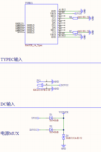
1. A dual-input interface of TYPEC and DC007 has been designed, supporting main and backup power supply. Two SMB-packaged SS54 microcontrollers are used as a MUX to supply power to the subsequent DC-DC circuit. (TYPEC interface: 0.5 RMB; SS54: 0.07 RMB; both are available on Taobao).
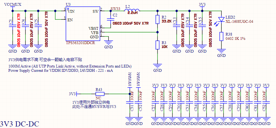
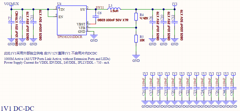
2. The power supply section of the original design was optimized. Due to distrust of the RTL8367S's on-chip DC-DC converter, the required 3V3 and 1V1 voltages are all supplied externally (I love drawing power supplies, and I also love spicy food). The DC-DC power chip was replaced with the inexpensive (0.24 RMB) TPS563201 synchronous Buck controller. This controller supports 4.5-17V input, has a switching frequency of 580kHz, a VFB reference of 0.768V, and a maximum output current of 3A, which is sufficient for this design. To facilitate capacitor parameter adjustment, the input and output filter capacitors in this design use 0805 packages, while the feedback resistors and bootstrap capacitors are 0603 packages. The feedback resistor values are typical values (10K, 33.2K, 4.42K), which can be purchased in most stores. The specific capacitance values of the input and output capacitors are based on TI's webench and personal experience; theoretically, this capacitance is sufficient to support a 3A load.

Due to space limitations, the power supply layout in this design is not optimal. I have tried my best to optimize the power supply layout. If you have a better layout recommendation, you can modify this design accordingly.
III. Interface Section
: Due to limited board space, it is difficult to fit a traditional network transformer. Therefore, other methods must be used. This design directly uses the integrated network transformer's network port (HR911130A), but this port is relatively expensive. If cost is a concern, you can consider the solution of TVS + DC blocking capacitor + common mode inductor + autotransformer.
IV. Pin Configuration:
PIN45-PIN56 are disabled and connected to a 1K pull-down resistor. For PIN51-56, the chip datasheet clearly states "[This pin must be pulled low with a 1K ohm resistor when not used.
]". PIN45-50 are not explicitly required by the datasheet, so they are also treated as 1K pull-down resistors.

PIN13, according to the chip datasheet, is connected to a 2.49K 1% error resistor.
PIN60: EN_SWR. According to the chip datasheet,
[Pull Up: Enable Internal Switching Regulator.
Pull Down: Disable Internal Switching Regulator.
This pin must be pulled high or low via an external 1k ohm resistor during normal operation.]
Here, we disable the chip's internal switching circuit by pulling it down to GND via a 1k ohm resistor.
PIN70: EEPROM Mode Selection. Select according to the EEPROM capacity.
Pull Up: EEPROM 24Cxx Size greater than 16Kbits (24C32-24C256).
Pull Down: EEPROM 24Cxx Size less than or equal to 16Kbit (24C02-24C16).
Note: This pin must be kept floating, or pulled high or low via an external 4.7k ohm resistor upon power on or reset.
This design uses 24C64, therefore a pull-up is used.
PIN73: EN_PWRLIGHT. When the RTL8367S powers on, all network port LEDs will blink once. You can pull EN_PWRLIGHT low to disable this blinking process. Here, we choose to enable blinking to easily confirm whether the chip has successfully loaded the firmware.
Connect to a 4.7K pull-up.
PIN74: Enable SPI FLASH Interface. Controls whether to enable SPI FLASH.
Pull Up: Enable FLASH interface
Pull Down: Disable FLASH interface
This design uses IIC FLASH, so connect to a 4.7K pull-down to disable the SPI FLASH interface.
PIN75: Disable Embedded 8051. Controls whether to enable the internal 8051.
Pull Up: Disable embedded 8051
Pull Down: Enable embedded 8051
This design requires firmware loading, so connect to a 4.7K pull-up to enable the internal 8051.
PIN76: Disable EEPROM/FLASH Autoload. Controls whether to automatically load firmware.
Pull Up: Disable EEPROM/FLASH autoload
Pull Down: Enable EEPROM/FLASH autoload
This design requires firmware loading, therefore the 4.7K pull-down pin allows automatic firmware loading.
PIN79: Enable Embedded PHY. Controls whether to enable the chip's internal embedded PHY.
Pull Up: Disable EEPROM/FLASH autoload
Pull Down: Enable EEPROM/FLASH autoload
We naturally want to directly use the chip's integrated PHY, as the chip is directly connected to the grid transformer, therefore the 4.7K pull-up pin is used.
PIN81: EEPROM SMI/MII Management Interface Selection. Used to select the management interface. Here, we do not need management and will not configure it.
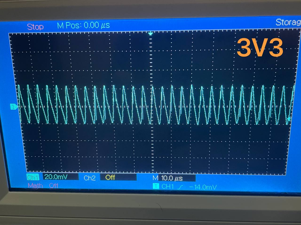
V. 3V3 and 1V1 Power Supply Test
Without a grounding pin, a grounding clip was used for testing. The ripple was 40mV, which is acceptable.

VI. Firmware Flashing
This design uses ST's M24C64, an 8KB EEPROM.
Please ensure that after writing the firmware, you read the firmware multiple times to ensure the read content is correct. If there are problems, please try changing the chip type, such as selecting another model like M24C32 in the programming software.
VII. Speed Test


 京公网安备 11010802033920号

 HF32F/018-Z3XXX


