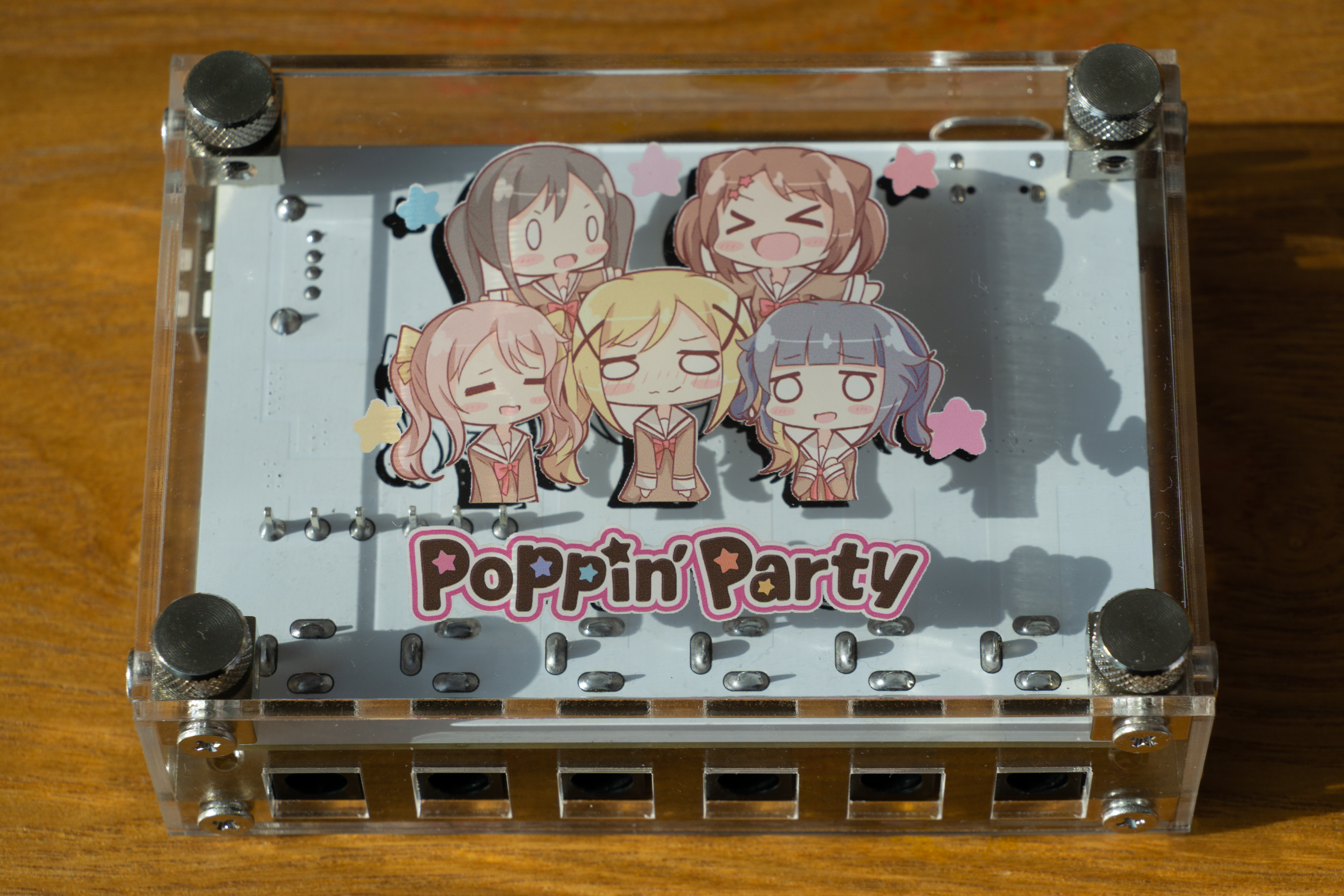
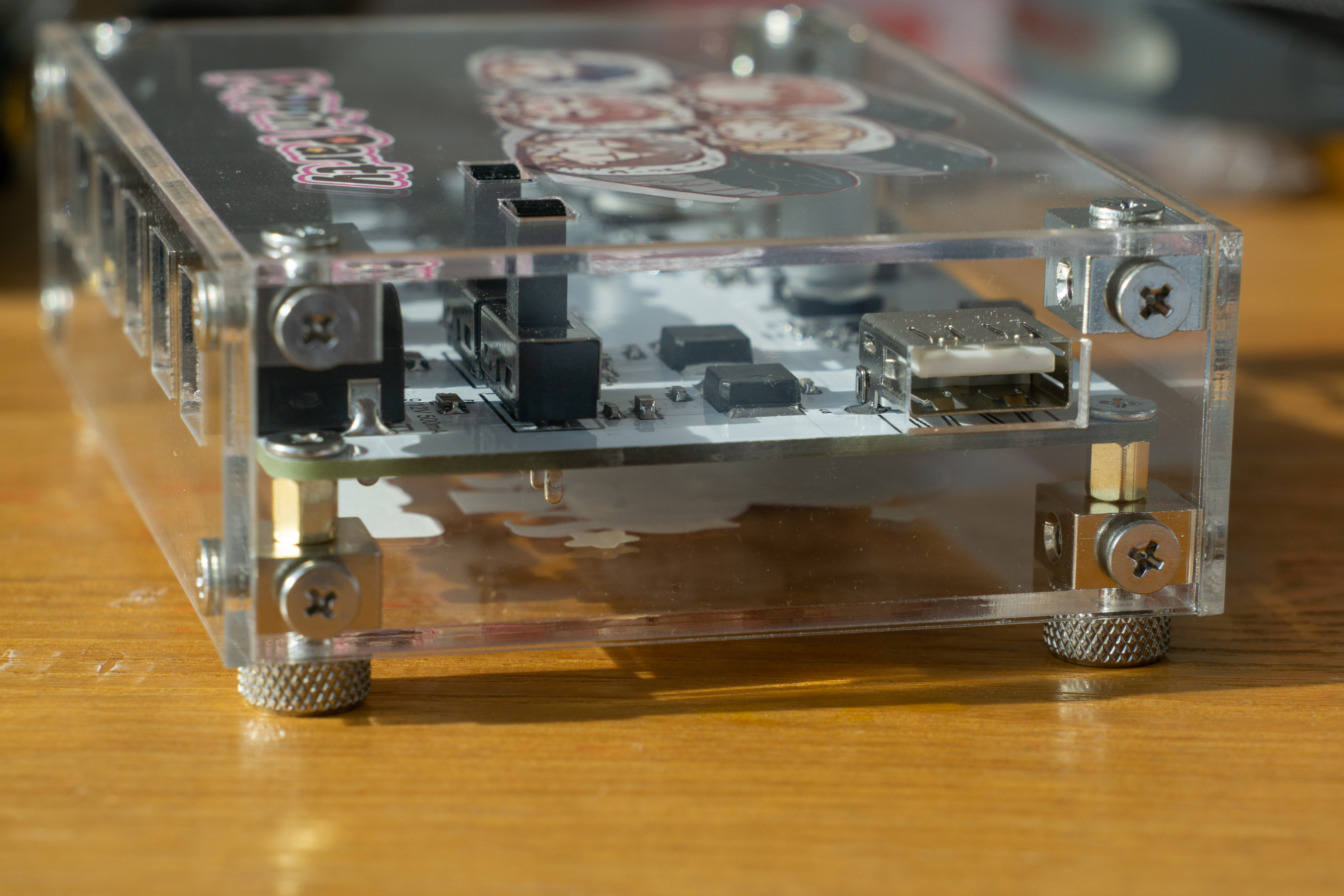
This is
a power supply for an effects unit using USB PD input. It features four fixed 9V outputs (500mA each), two selectable 9V/12V outputs (500mA each), and one USB-A output port (5V 1A).
Important notes:
All DC outputs are externally positive and internally negative, and each has an individual resettable fuse. The power supply for the USB-C input must support the PD protocol and be able to output 12V.
Screw and nut selection: M3+4mm flathead screws are used, bottom screws are M3 thumbscrews, copper pillars are M3*5+3 single-headed copper pillars, and the square tee nuts are 10*10*6mm.
Slide switch selection: The sample shown is SS12D10G9, 9mm high, only slightly exceeding the top shell. A longer one couldn't be found. If found, a longer
shell could be used with JLCPCB panel printing, 2mm thick, and printed on the back. The original source of the patterns on the shell and PCB could not be found; thanks to the original creator!
Sample image:

PDF_Effector_Power.zip
Altium_Effector_Power.zip
PADS_Effector_Power.zip
BOM_Effector_Power.xlsx
91144
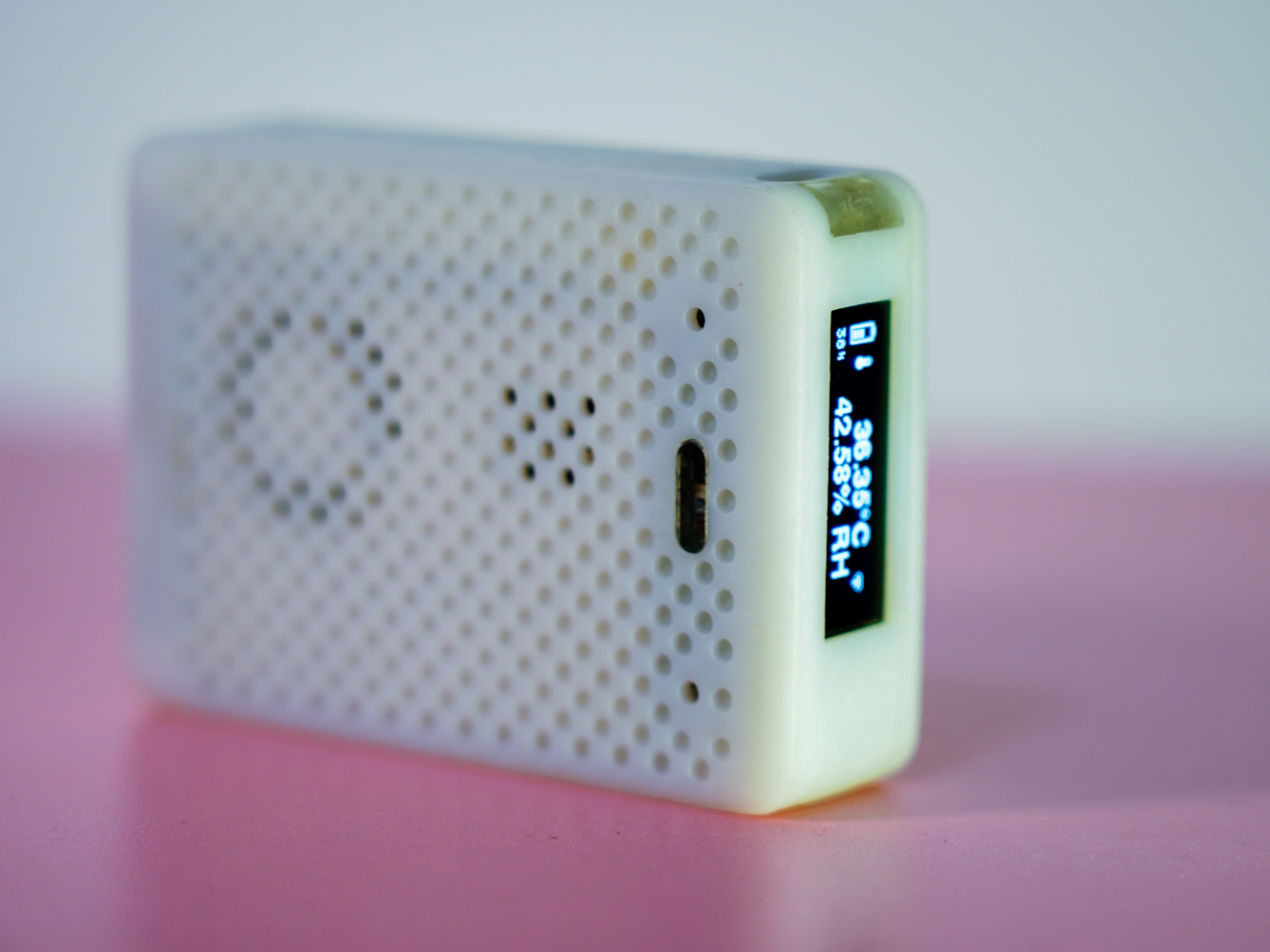
Whole-house environmental quality monitoring station based on ESP32-C3
This information acquisition node is used in whole-house smart control systems. Based on the low-power design of ESP32-C3, it can acquire indoor PM2.5, TVOC, ambient temperature, humidity, air pressure, and illuminance. It supports infrared remote control and reception and uploads environmental information via WiFi.
Video link for a whole-house environmental quality monitoring station based on ESP32-C3
:
JLCPCB ESP32 IoT Call for Entries – Whole-House Environmental Quality Monitoring Station Based on ESP32-C3
Project Introduction:
Sensors are a crucial component of smart homes. While various smart sensors are available on the market, they are typically closed-source. Therefore, I wanted to develop my own smart sensor. It can connect to Home Assistant and integrate with smart home systems like Mi Home. One sensor can be placed in each room, acting as an independent monitoring station to record environmental changes in each room and control individual air conditioners, air purifiers, curtains, and lights. Besides sensing traditional data, its most important feature is its compact size; it can be placed on a table, hung on a wall, or placed by the bedside. It also boasts long battery life, lasting up to half a month on a single charge.
Project Functionality
: The ESP32-C3 is a secure, stable, low-power, and low-cost IoT chip from Espressif Systems. It features a RISC-V 32-bit single-core processor and supports 2.4 GHz Wi-Fi and Bluetooth 5 (LE). Based on this, and paired with several peripheral sensor chips, our sensors can detect and upload the following key indoor environmental indicators:
temperature,
humidity ,
air pressure, estimated altitude,
PM.5 and PM10,
ambient light intensity,
and eTVOC (volatile organic compounds) .
In addition to the aforementioned sensors, the eTVOC monitoring station also has a series of locally interactive peripherals:
a 0.91-inch OLED screen that displays the station's battery level, time, signal strength, and information collected by each sensor;
a button for switching display pages and waking from sleep mode;
a set of three-color breathing lights to indicate battery charging, network connection status, and operating status;
a buzzer for issuing remote control prompts; and
a USB Type-C interface for charging and debugging. Since it's a
monitoring
station, measurement is its primary function. The performance indicators of the main measurement parameters are as follows:
Temperature measurement accuracy: ±0.5% (low power consumption operation)
; Humidity measurement accuracy: ±3%;
Air pressure measurement accuracy: ±0.5 hPa
; PM2.5 measurement
accuracy: ±10%; Ambient light measurement accuracy: ±0.5%;
TVOC measurement accuracy: 0.5 ppm
; Angle measurement accuracy: 0.1°
; Vibration measurement accuracy: 0.2 m/s².
The working environment requirements are as follows:
Working temperature range: -10℃ ~ 60℃;
Working humidity range: 0% ~ 99% (non-condensing);
Working pressure range: 300~1250 hPa (0 ~ 9000m @ 25℃)
; PM2.5 measurement range: 0-500 ug/m³
; Illuminance measurement range: 0~83865 Lux;
TVOC concentration range: 0~1000 ppm;
Angle measurement range: 0~360° (each axis)
; Vibration measurement range: ±40 m/s² (each axis).
The monitoring station's own parameters are as follows:
Dimensions: 70 × 50.1 mm. × 16 mm
Weight: 60 g
Battery Capacity: 500 mAh
Low Power Consumption: 22 days
WiFi Band: 2412~2484MHz
Hardware Description
This indoor monitoring station consists of the following main parts: 1) Main control board, 2) Sensor board, 3) FPC board, 4) Battery, 5) PM2.5 sensor module, 6) WiFi antenna, 7) Housing. The main control board circuit block diagram is shown in Figure 1, and the sensor board circuit block diagram is shown in Figure 2.

Figure 1--Main Control Board Circuit Block Diagram
All circuit designs of the main control board are basically based on the low power consumption design of ESP32-C3.
The Espressif Systems ESP32-C3 connects to a WiFi antenna for internet access and sleeps when inactive to reduce power consumption.
An on-chip ADC, along with I/O, collects battery voltage and provides charging alerts with very low power consumption via I/O control.
I2C connects to most sensors, controls the OLED screen and LED breathing light display, and manages sensor board status information via I/O expanders. The OLED screen's I2C is isolated from the bus, so disconnecting the OLED does not affect bus operation.
The serial port connects to the PM2.5 sensor module and reuses the infrared control and receiving modules; disconnecting the I/O when not in use results in almost no power consumption.
The USB port connects to a Type-C-16P interface, using built-in CDC and JTAG for downloading and debugging, as well as power supply and charging; disconnecting the I/O when not in use results in almost no power consumption.
GPIO manages the device's power supply, charging status, low-power control, peripheral reset, and button reading, with only a small amount of power consumption during control enable.
LEDC controls the buzzer output and consumes no power when not in use.

Figure 2 – Sensor Board Circuit Block Diagram.
Due to space constraints and the fact that the ESP32-C3 can only connect to a limited number of I/O interfaces, the sensor board is designed around the I/O expander, sharing the I2C bus and connecting to the motherboard via a 10-pin connector.
The I/O expander is used to collect interrupts from each sensor and control sensor power supply and signal switching, etc.;
the EEPROM is used to store calibration data and sensor hardware information, facilitating subsequent updates and backward compatibility with the sensor board;
the accelerometer/angular velocity sensor is used to detect the spatial position of the device and can control screen flipping and vibration detection;
the ambient light sensor can obtain indoor light intensity and control the display brightness of the device;
the temperature and humidity sensor can measure indoor temperature and humidity;
the barometer can measure indoor air pressure and temperature;
the TVOC sensor can measure indoor organic matter and carbon dioxide content;
the infrared transmitter is used for device remote control, and the infrared receiver can learn special remote control commands;
the PM2.5 module is relatively large and built into the casing, connecting to the sensor board and main control board via an FPC flexible cable.

Figure 3 – Main Control Board Power Block Diagram.
The power architecture design directly affects the low-power performance of the entire device. The selection principle prioritizes lower power consumption, and the wake-up and sleep currents for each circuit module are marked.
Battery management uses a charging chip with path management; part of the current from the USB input powers the battery, and part powers the system, extending battery life.
The main power supply is divided into three paths: one path goes to an ultra-low-power buck chip, converting it to 3.3V for the main system; the three-color LED driver chip can achieve self-low-power management and is directly connected to the main power path; the boost circuit is controlled and has a built-in output shutdown function, used to power the PM2.5 module.
The 3.3V power supply is also divided into three paths: one path is directly connected to the ESP32-C3, ensuring that the RTC clock always works even in sleep mode; the OLED screen power supply is controlled, only connected to the power supply when the display is woken up; most sensor connections are uncontrolled, as most have sleep or standby modes, and the infrared transceiver uses the same logic as the serial port, only powering on when the infrared function is used;
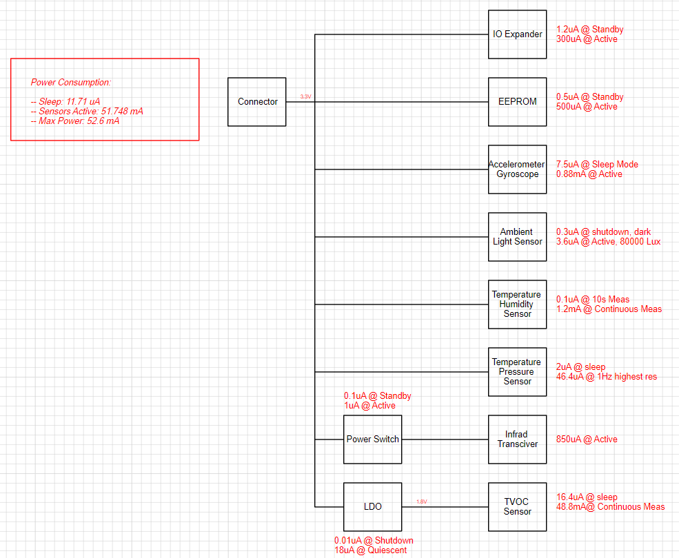
Figure 4 - Sensor Board Power Supply Block Diagram.
The TVOC sensors on the sensor board require 1.8V power supply and do not have sleep mode, so an LDO with enable is selected for controlled processing. In this way, the sensor board only requires 11.71uA when all sensors are in sleep mode, and consumes 52.6mA when all sensors are woken up.
Based on the current consumption of each circuit module, the following current budget table was obtained:

Figure 5 - System Current Budget Table
. Based on unattended use, we set the sleep time percentage to 99%, the sensor wake-up time (excluding PM2.5) to 0.9%, the wake-up time for all sensor modules to 0.09%, and the time for maximum WiFi transmission power consumption to 0.01%. This roughly calculates an average current of approximately 0.91mA. Thus, a small 500mAh lithium battery can last for nearly 23 days! If 10% of the battery is reserved for heartbeat wake-up, it's sufficient for 20 days of normal use.
Circuit fabrication:
First, thanks to JLCPCB for the coupons and fast prototyping, which greatly shortened the development cycle.
Due to time constraints, we had LCPCB SMT mount 5 components for this prototyping, which yielded excellent results, much better than hunching over to solder the board.
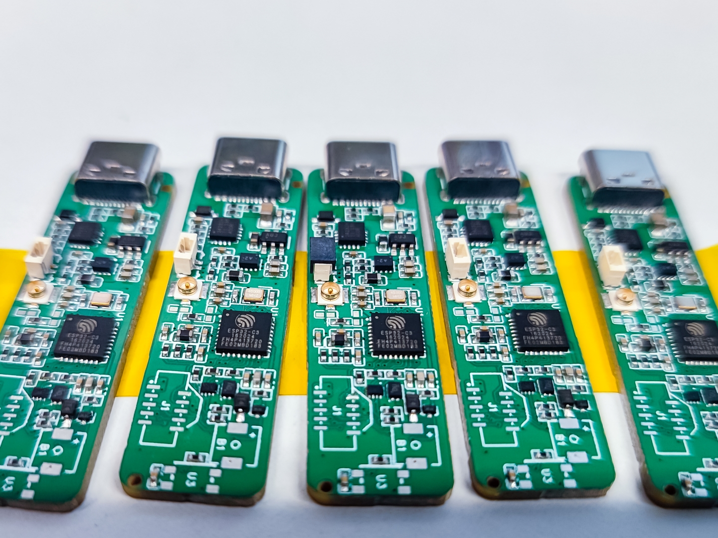
Figure 6 - Board returned from LCPCB SMT.
After adding the remaining missing components, the main control board is ready.
Since the sensor boards were too small to be mounted on the machine, we ultimately chose to create a stencil and solder them ourselves. The components are not difficult to solder, so no pictures are included. For those with the financial means, you can also get it done through JLCPCB.
LCPCB's one-stop service is excellent; with a coupon, the FPC sample printing is practically free, and it arrived quickly. I soldered the socket and tested it—perfect.
Then I bought a battery and FPC antenna from Taobao. Here's a family photo!
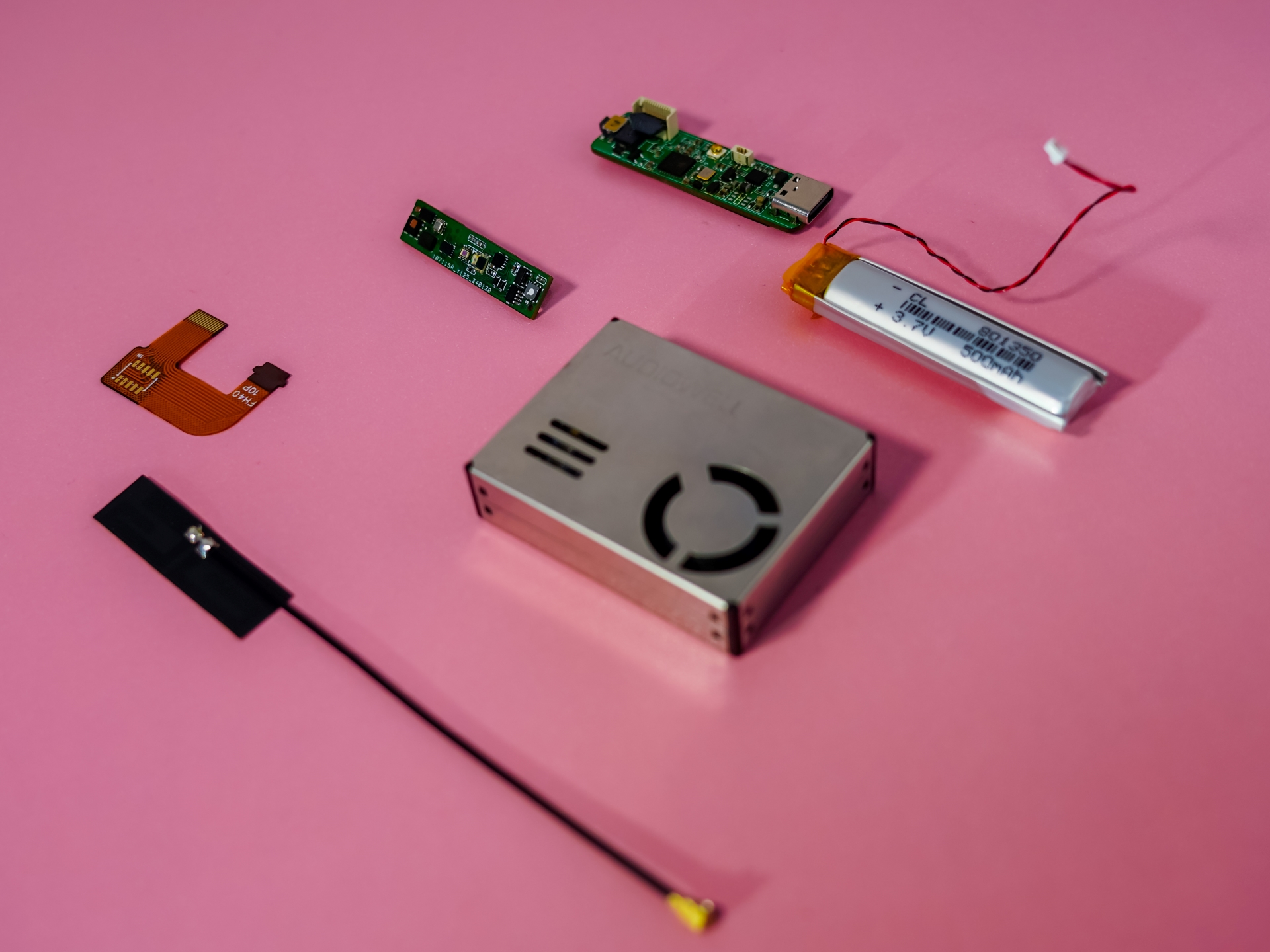
Figure 7—Hardware Family Photo. The structural components
for
the sensor were drawn in Fusion360 and printed by JLCPCB. A total of five shell parts were printed, including the main body, back cover, semi-transparent light window, transparent window, and buttons.
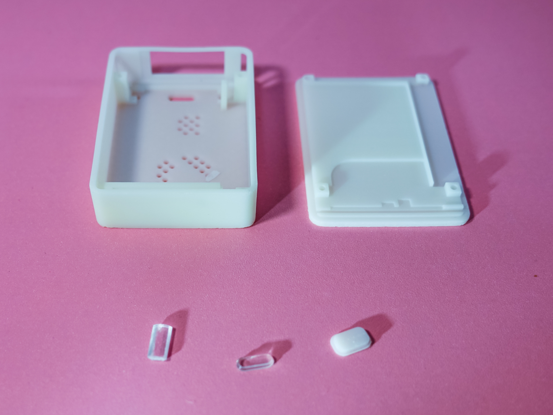
Figure 8—Structural Components Family Photo .
Assembly wasn't difficult. Insert the transparent parts into the main body, place the buttons in their corresponding holes, and you can easily install the motherboard by snapping it into the slot in the main body.
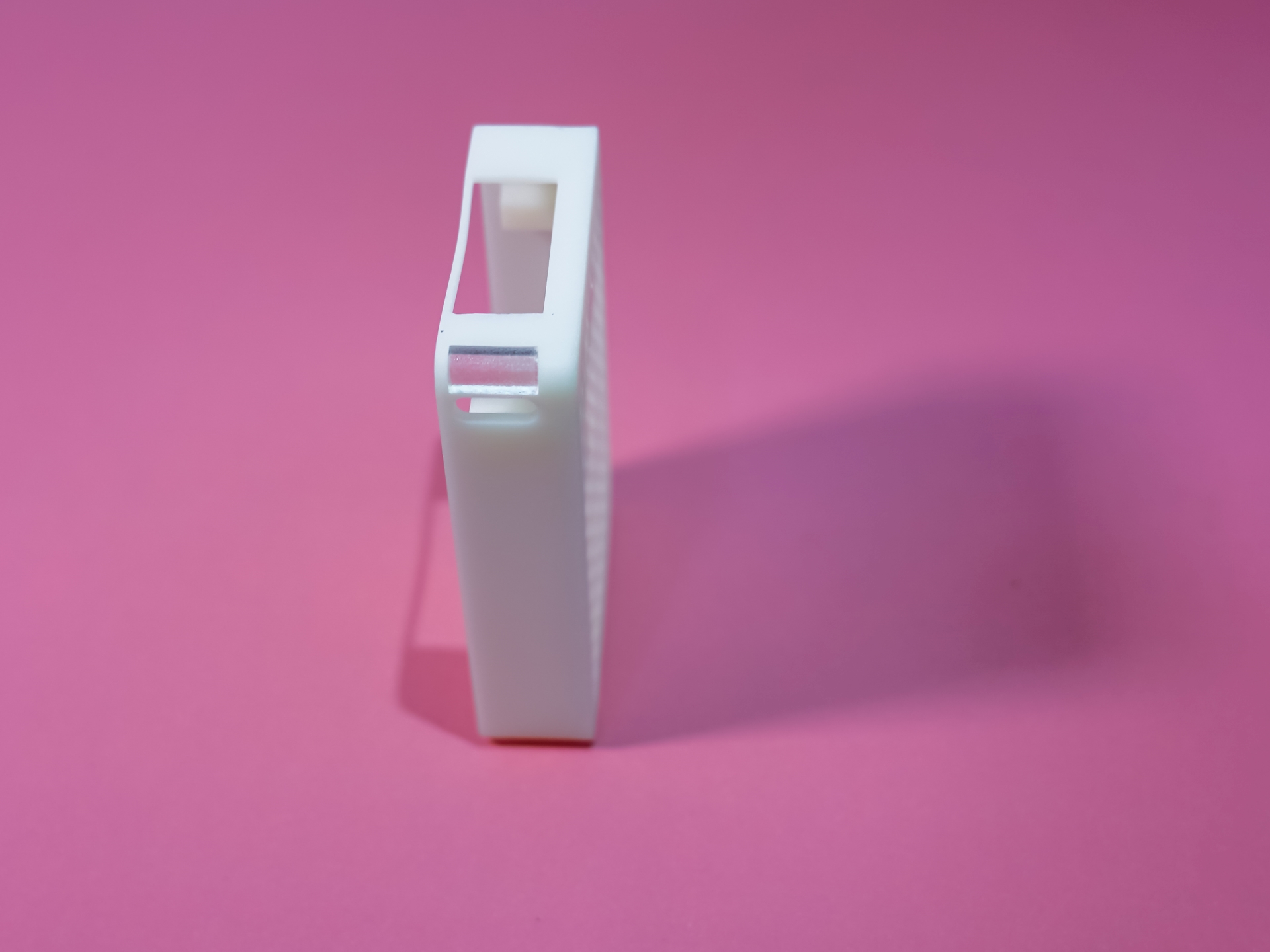
Figure 9—Semi-transparent Light Window Installation .
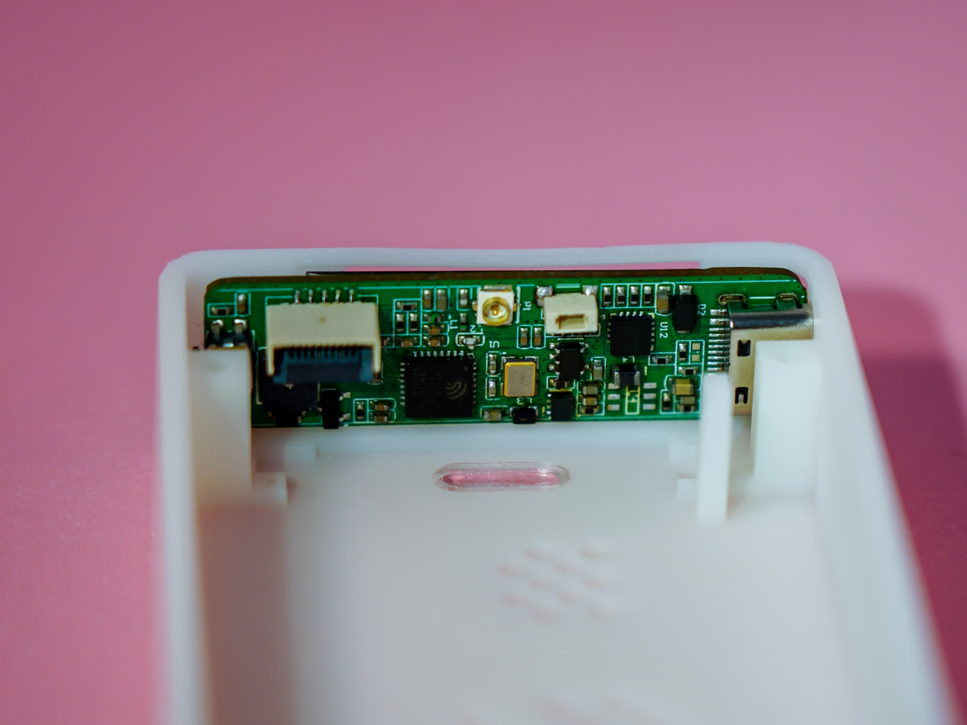
Figure 10—Window and Main Control Board Installation.
Then, I placed the PM2.5 sensor and sensor board inside. The sensor motherboard is secured to the bottom shell with M1 screws. The printing precision determines whether installation will be successful; if it's too tight, tighten it; if it's too loose… just loosen it a little, as long as the screws don't fall out.
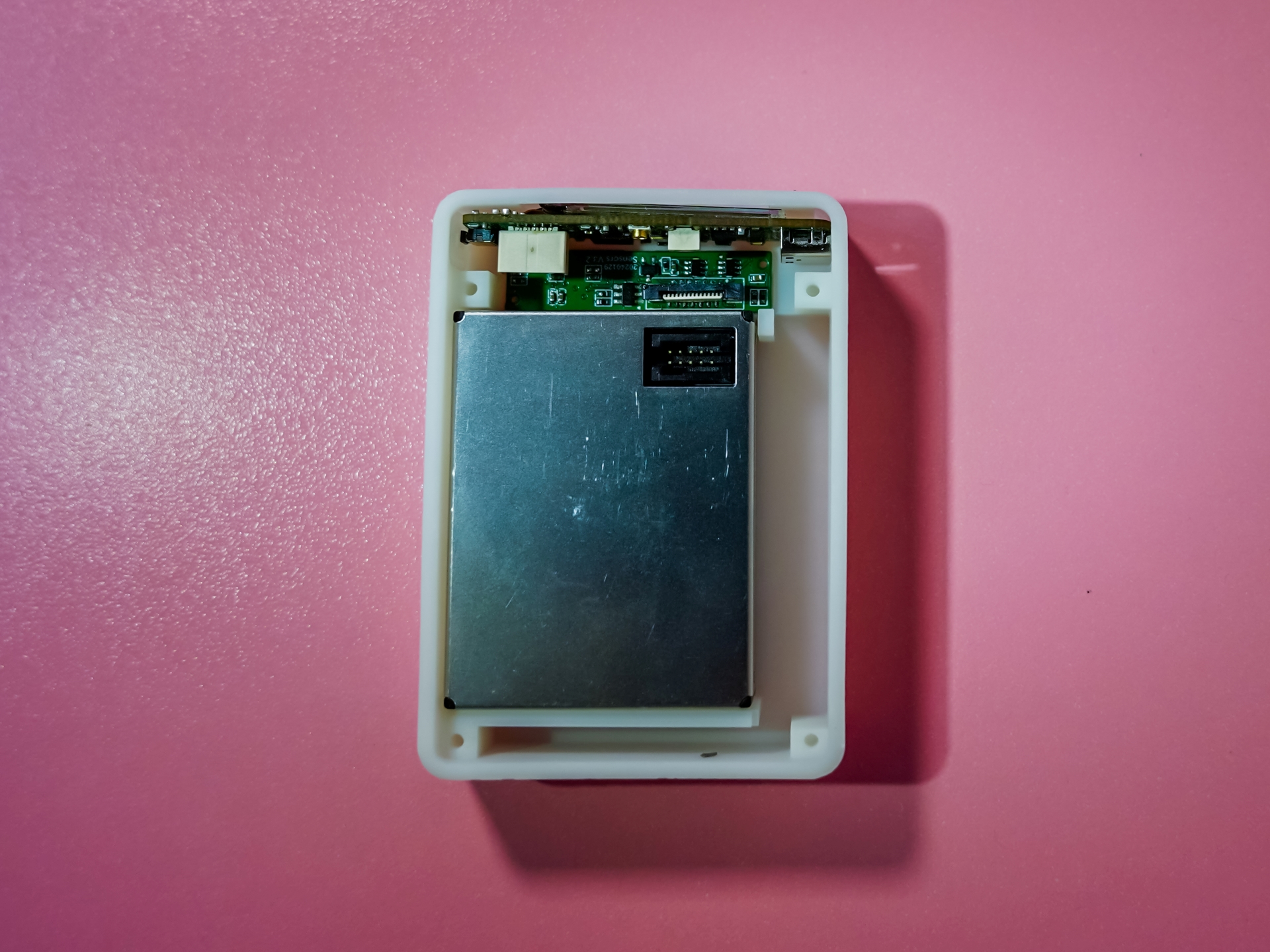
Figure 11 – PM2.5 Sensor and Sensor Board Installation:
Install the battery, FPC antenna, and FPC cable, tidy up the wiring. You can see that this small PM2.5 module already occupies 70% of the entire unit's area. With the battery and other components, the overall space is quite compact.
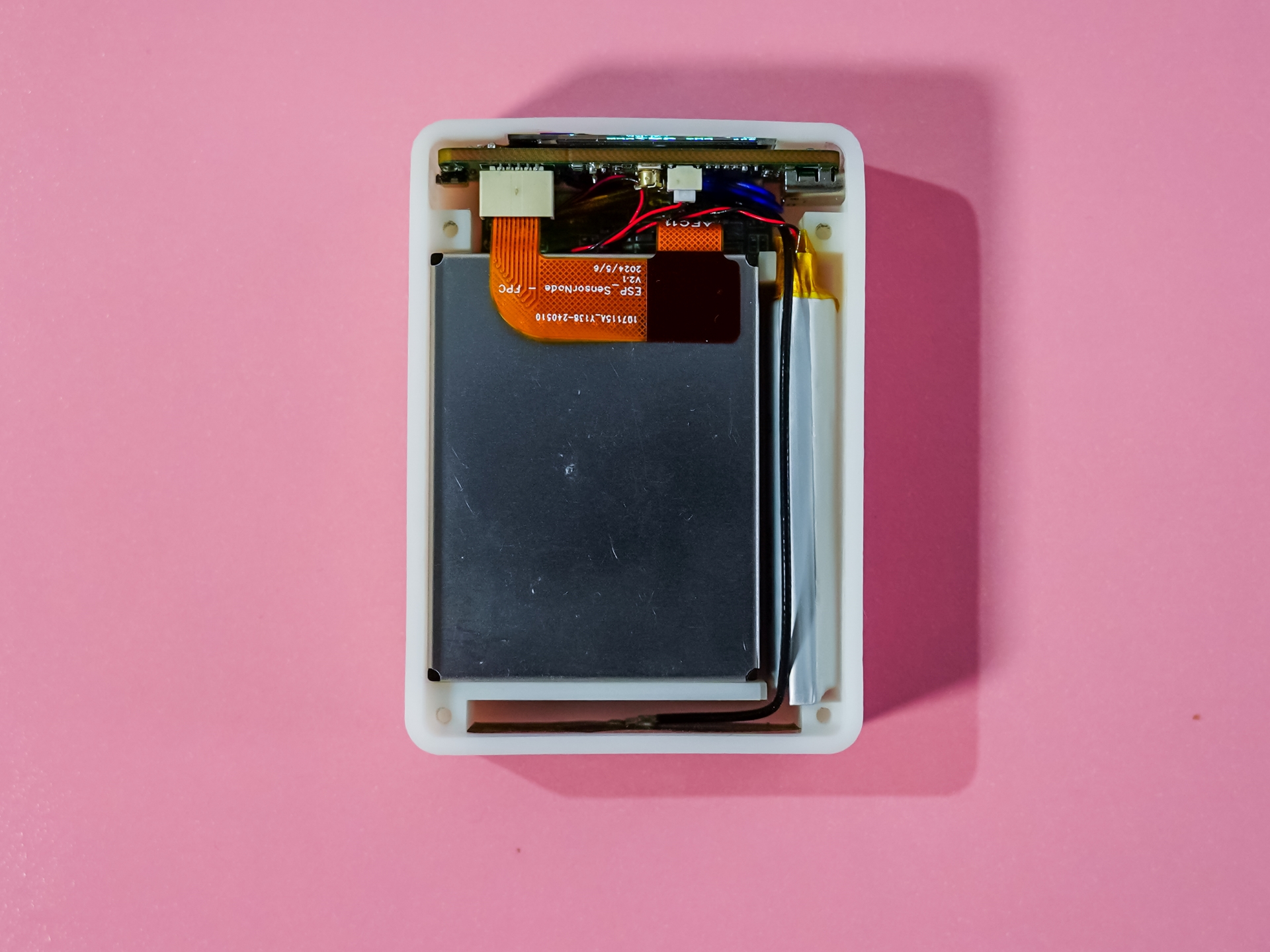
Figure 12 – Remaining Component Installation:
Finally, we put on the back cover and tighten the four M2 screws. Our smart monitoring station is now complete!

Figure 13 – Success!
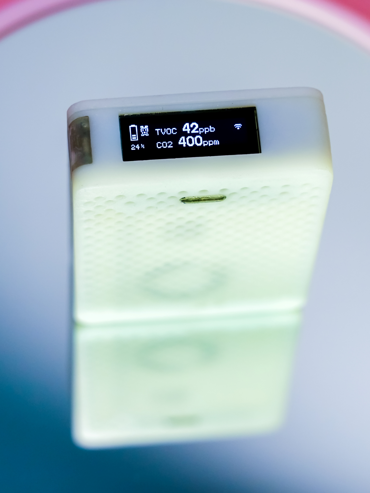
Figure 14 – Taking an Artistic Photo:
Software Design:
The software is designed based on PlatformIO and Arduino, currently written in bare metal. The block diagram is as follows:
Figure 14 – Software Flowchart:
After waking up the device, the initialization process begins.
After completing IO initialization, the online status of each sensor is checked, and the cause of any errors is investigated to prevent subsequent crashes.
Next, the LED driver is initialized. The LED driver is an independently operating control chip; after receiving a control command, it doesn't need to occupy the CPU and can automatically complete the breathing light effect.
Calibration information and the list of mounted devices are read from the EEPROM. If a device doesn't match the online sensor, the corresponding initialization is skipped and won't be called again later.
The OLED initialization is determined based on the power status; if the user wakes it up by pressing a button, initialization is performed.
Next, WiFi connection and network time synchronization are performed. The network connection hasn't been optimized yet; the SSID and password need to be written before compilation.
Once everything is ready, each sensor module is initialized, and calibration parameters are written.
The loop first handles interrupt flags and retrieves information from the corresponding sensors, such as temperature and humidity sensors and light sensors.
After handling the interrupt, network information and general sensor information are read, and finally displayed on the OLED or sent to the HA.
The low-power section still needs improvement and some optimization is required.
For program burning, a USB Type-C cable can be used to connect to a computer, compile in VSCode, and then upload to start working.
In closing,
I'd like to thank Espressif Systems and JLCPCB for their generous support of this event, which allowed group members to benefit and provided an opportunity for everyone to create something interesting and exchange ideas.
The event was short-lived, and as a full-time office worker, I only had two or three hours a day to work on it. The project progressed with some setbacks, and I frantically worked on it for the last two days. Many details remain unresolved, and I'll continue to refine it. I humbly request the help of all the experts...
PDF_ESP32-C3-based Whole House Environmental Quality Monitoring Station.zip
Altium_ESP32-C3-based Whole House Environmental Quality Monitoring Station.zip
PADS_ESP32-C3-based Whole House Environmental Quality Monitoring Station.zip
BOM_Whole House Environmental Quality Monitoring Station Based on ESP32-C3.xlsx
91145
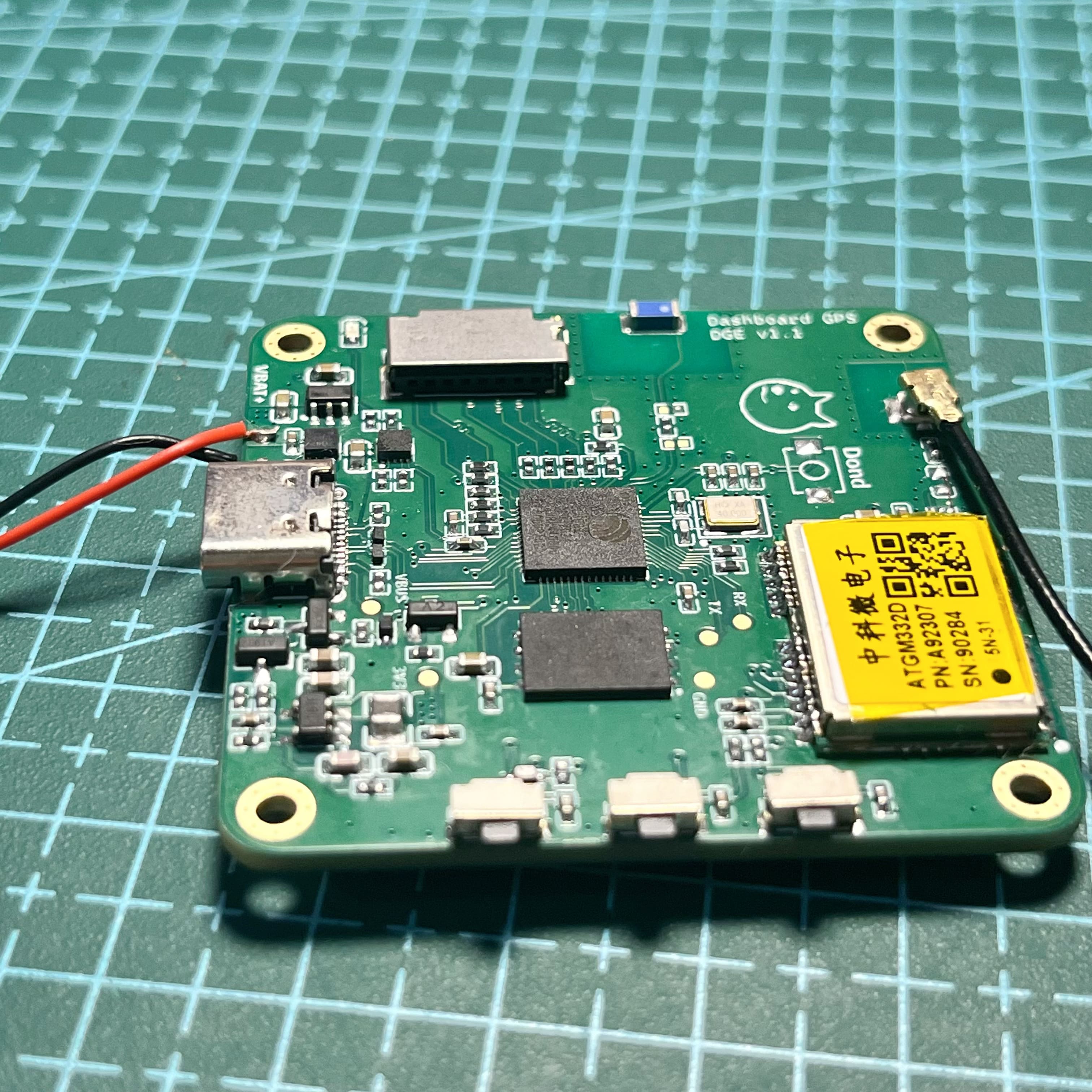
GPS-ESP32S3 dashboard
This is a GPS dashboard (speedometer) designed using the ESP32.
GPS Dashboard for ESP32-S3
This is a GPS dashboard/speed meter developed using LVGL9.2 and based on the ESP32S3 as the main control UI framework .
It was only ported and completed on the 16th. I'm going out for the Mid-Autumn Festival, so the casing isn't finished yet; I'll work on it when I have time.
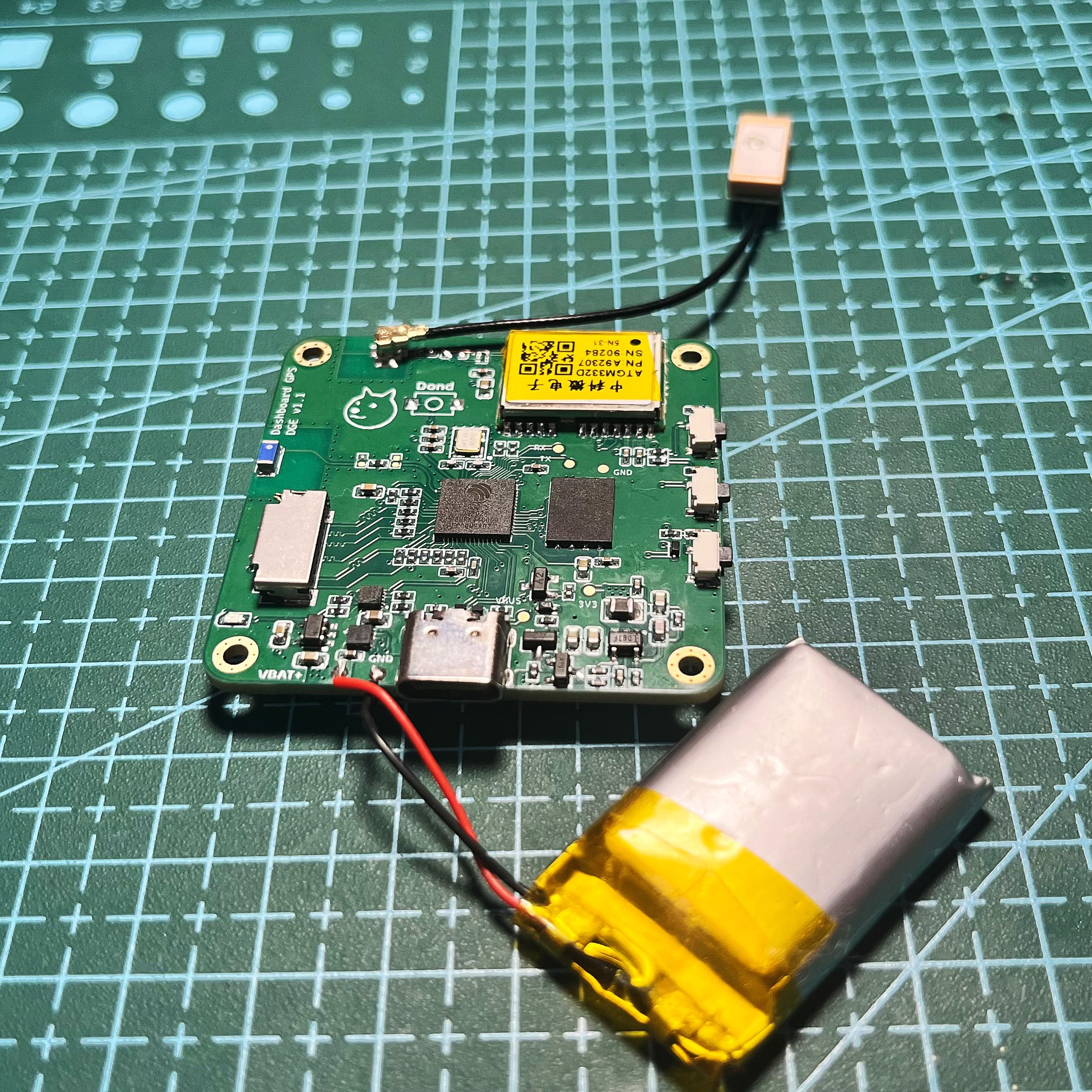
1. Hardware Design
Integrated charging chip, supporting 3.7V battery charging, automatic power path management.
Integrated fuel gauge chip.
Designed with a one-button power on/off circuit.
Uses Zhongke Micro's GPS module.
The main control is ESP32-S3R8.
Built-in PSRAM 8 MB (Octal SPI).
External Flash 16M.
Designed with SD/TF card with SDIO interface.
Uses ESP32-USB peripheral debugging.
Three user buttons, one of which is the power button.
1.1 Automatic Power On/Off
This is a common circuit design, using a PMOS to control the positive terminal of the battery to connect to the system.
By default, the gate (G) of the PMOS is pulled high by a 1K resistor, cutting off conduction. In reality, it's difficult for a PMOS to be completely cut off. A larger pull-up resistor results in a larger leakage current; even with a 1K resistor, there's still leakage current, approximately 1.5~2V.
When the KEY1 button is pressed, it conducts to GND, pulling the gate (G) of the PMOS low, effectively short-circuiting the source and drain. At this point, the ESP32 microcontroller is powered on at 3.3V via the DC-DC step-down circuit. Once powered on, the ESP32 sets a high level on the POWER-EN pin, turning on the NMOS and pulling the PMOS's gate low. Releasing the button keeps the PMOS conducting. To power off, the ESP32 sets a low level on the POWER-EN pin.
1.2 Charging IC
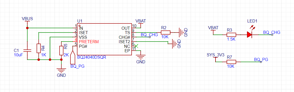
: A single-cell lithium battery 3.7V charging IC is selected. When a power source is detected, BQ-PG is pulled low, allowing the microcontroller to detect the power supply connection. This can be linked to the charging state switching of the LVGL.
1.3 Fuel Gauge

This fuel gauge uses an I2C peripheral driver. The GAS-INT pin is pulled low when the battery is low, sending a low battery signal to the ESP32.
Linking with LVGL allows for battery level detection, and linking with the charging IC provides a comprehensive overview of charging information.
2. Software Design
and Development Editor: VS Code
Framework: ESP-IDF V5.3.1
Simulator: VS Code + SDL
UI: LVGL 9.2
UI Design The UI


project framework is designed modularly, using CMake to manage
the LVGL source code and project UI code (framework). One codebase is used by both the SDL simulator and ESP32IDF. CMake environment variables distinguish different environment build files.
The script folder provides a font generator, image generator, and image compositer (multiple images are generated into a single .bin file). All scripts are written in Python.
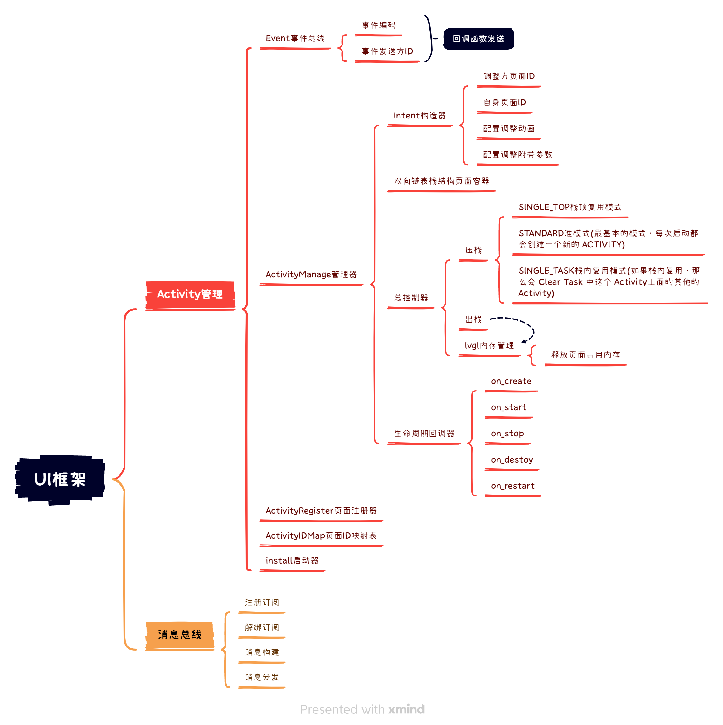
2.1 LVGL Page Framework
The core algorithm of the page management framework is a doubly linked dynamic list for management.
Functions include
various lifecycle callback controls,
page animation controls,
dynamic parameters,
a message bus (EventBus),
page operation tools, methods,
components, memory management
(lv_group), input event grouping management
(lv_indev), redefining input callbacks, key types
, etc.
2.2 LVGL Font Design
A font generation tool was written in the Script folder, generating a .c file by default. When using it, you only need to write a .json file, for example, the following:
{
"desc": "The tool for building fonts",
"outputPath": "output",
"fontFileConfigs": [
{
"fontPath": "./font/DigitalNumbers-Regular.ttf",
"generators": [
{
"size": 64,
"fileName": "font_dignumber_64.c",
"bpp": 4,
"symbols": "-",
"range": ""
},
{
"size": 16,
"fileName": "font_dignumber_16.c",
"bpp": 4,
"symbols": "KM/h",
"range": ""
}
]
},
{
"fontPath": "./font/DouyinSansBold.otf",
"generators": [
{
"size": 12,
"fileName": "font_douyin_12.c",
"bpp": 4,
"symbols": "When riding is not enabled, the automatic shutdown time is set to the maximum speed, average temperature, and maximum range of a single mileage. The range is: minutes, seconds, etc.",
"range": ""
},
{
"size": 16,
"fileName": "font_douyin_16.c",
"bpp": 4,
"symbols": "Exit settings hour minutes seconds tech black minimalist white close version official website cooperation contact user manual: good not connected cumulative mileage riding longitude latitude altitude current speed antenna status satellites available single highest average temperature dial style automatic sleep record positioning information on machine",
"range": ""
},
{
"size": 24,
"fileName": "font_douyin_24.c",
"bpp": 4,
"symbols": "Set dial style automatic sleep riding record positioning information about this machine shutdown",
"range": ""
}
]
}
]
}
2.3 LVGL image resource design
image generation also has small tools that can be used, in the img_script folder
tool usage instructions:
The `image` folder contains original files such as .png and
.jpg. The `img_scriptgen_img.py` script reads the images from the `image` folder
and generates all the `.bin` files. The `img_scriptgen_bin.py` script reads all the `.bin` files, merges them into one `.bin` file, and outputs a `.c` file containing a map address and a `mergin.bin` file.
An example of the generated map file is shown below
: `#include "mergin_bin.h"
struct mergin_bin_t bin_infos[] = {
{
.item_name = "battery.bin",
.start_address = 0,
.end_address = 812
} ,
{
.item_name = "dark_style_bg.bin", .start_address = 812, .end_address = 135224 }, { .item_name = "fire.bin", .start_address = 135224, .end_address = 136370 } ........................ };` size_t bin_infos_len = 16; 2.3.1 SDL simulator uses merge.bin #include #include #include #include "mergin_fsys.h" #ifndef BIN_DIR #define BIN_DIR "" #endif struct mergin_bin_t bin_infos[] = { { .item_name = "battery.bin", .start_address = 0, .end_address = 812 }, { .item_name = "dark_style_bg.bin", .start_address = 812, .end_address = 135224 }, .....................omitted }; size_t bin_infos_len = 16; void* bin_open_cb(lv_fs_drv_t* drv, const char* path,lv_fs_mode_t mode) { struct mergin_fs_t* fs = lv_malloc(sizeof(struct mergin_fs_t)); if (fs == NULL) { return NULL; } fs->mode = mode;
fs->path = path;
fs->mergin_bin = find_bin_by_name(strrchr(path, '/') + 1);
if (fs->mergin_bin == NULL) {
return NULL;
}
fs->user_data = fopen(BIN_DIR, "rb");
if (fs->user_data == NULL) {
lv_log("Cannot find/merge.bin file and failed to open");
lv_free(fs);
return NULL;
}
fseek(fs->user_data, fs->mergin_bin->start_address, SEEK_SET);
return fs;
}
lv_fs_res_t bin_close_cb(lv_fs_drv_t* drv, void* file_p) {
struct struct mergin_fs_t* fs = (struct mergin_fs_t*)file_p;
if (fs->user_data != NULL) {
fclose(fs->user_data);
}
lv_free(fs);
return LV_FS_RES_OK;
}
lv_fs_res_t bin_read_cb(lv_fs_drv_t* drv,
void* file_p,
void* buf,
uint32_t btr,
uint32_t* br) {
struct mergin_fs_t* fs = (struct mergin_fs_t*)file_p;
*br = fread(buf, 1, btr, fs->user_data);
return (*br > 0) ? LV_FS_RES_OK : LV_FS_RES_UNKNOWN; // Return result
}
lv_fs_res_t bin_seek_cb(lv_fs_drv_t* drv,
void* file_p,
uint32_t pos,
lv_fs_whence_t whence) {
struct mergin_fs_t* fs = (struct mergin_fs_t*)file_p;
if (whence == LV_FS_SEEK_SET) {
return fseek(fs->user_data, fs->mergin_bin->start_address + pos,
SEEK_SET) != 0
? LV_FS_RES_UNKNOWN
: LV_FS_RES_OK;
} else if (whence == LV_FS_SEEK_END) {
return fseek(fs->user_data, fs->mergin_bin->end_address - pos,
SEEK_SET) != 0
? LV_FS_RES_UNKNOWN
: LV_FS_RES_OK;
} else if (whence == LV_FS_SEEK_CUR) {
return fseek(fs->user_data, pos, SEEK_CUR) != 0 ? LV_FS_RES_UNKNOWN
: LV_FS_RES_OK;
}
return LV_FS_RES_UNKNOWN;
}
lv_fs_res_t bin_tell_cb(lv_fs_drv_t* drv, void* file_p, uint32_t* pos_p) {
struct mergin_fs_t* fs = (struct mergin_fs_t*)file_p;
long pos = ftell(fs->user_data);
*pos_p = pos - fs->mergin_bin->start_address;
return *pos_p < fs->mergin_bin->end_address ? LV_FS_RES_OK
: LV_FS_RES_UNKNOWN;
}
2.3.2. ESP-IDF uses mergein.bin
When using merge.bin with ESP-IDF, this file needs to be added to CMakeLists.txt. The ESP-IDF tool will package this file into the .rodata section of Flash.
First, you need to edit the contents of CMakeLists.txt in the main folder and add the path to merge.bin:
idf_component_register(SRC_DIRS "." "font/"
INCLUDE_DIRS "include"
EMBED_FILES "../../scripts/img_script/merge_output/merge.bin")
It is recommended to use relative paths.
Use variables to reference data in the .rodata section in the code. Core code:
// Get files in the .rodata section of Flash
extern const uint8_t merge_start[] asm("_binary_merge_bin_start");
extern const uint8_t merge_end[] asm("_binary_merge_bin_end");
The complete code for writing the Flash virtual file system is as follows. After writing the code below, you can use the images.
#include
#include
#include
#include "mergin_fsys.h"
// Get the file in the .rodata section in Flash
extern const uint8_t merge_start[] asm("_binary_merge_bin_start");
extern const uint8_t merge_end[] asm("_binary_merge_bin_end");
struct mergin_bin_t bin_infos[] = {
{.item_name = "battery.bin", .start_address = 0, .end_address = 812},
{.item_name = "dark_style_bg.bin",
.start_address = 812,
.end_address = 135224},
{.item_name = "fire.bin", .start_address = 135224, .end_address = 136370},
{.item_name = "gps.bin", .start_address = 136370, .end_address = 136894},
{.item_name = "power.bin", .start_address = 136894, .end_address = 137706},
{.item_name = "record_start.bin",
.start_address = 137706,
.end_address = 138968},
{.item_name = "record_stop.bin",
.start_address = 138968,
.end_address = 140230},
{.item_name = "setting.bin",
.start_address = 140230,
.end_address = 141394},
{.item_name = "set_active.bin",
.start_address = 141394,
.end_address = 142206},
{.item_name = "set_back.bin",
.start_address = 142206,
.end_address = 143018},
{.item_name = "set_gps.bin",
.start_address = 143018,
.end_address = 143830},
{.item_name = "set_info.bin",
.start_address = 143830,
.end_address = 144642},
{.item_name = "set_log.bin",
.start_address = 144642,
.end_address = 145454},
{.item_name = "set_ok.bin", .start_address = 145454, .end_address = 146266},
{.item_name = "set_sleep.bin",
.start_address = 146266,
.end_address = 147078},
{.item_name = "set_style.bin",
.start_address = 147078,
.end_address = 147890},
};
size_t bin_infos_len = 16;
void* bin_open_cb(lv_fs_drv_t* drv, const char* path, lv_fs_mode_t mode) {
struct mergin_fs_t* fs = lv_malloc(sizeof(struct mergin_fs_t));
if (fs == NULL) {
return NULL;
}
fs->mode = mode;
fs->path = path;
fs->mergin_bin = find_bin_by_name(strrchr(path, '/') + 1);
if (fs->mergin_bin == NULL) {
LV_LOG_ERROR("ERROR: Error BIN file resource not found");
return NULL;
}
uint32_t* pos = lv_malloc_zeroed(sizeof(uint32_t));
*pos = 0;
fs->user_data = pos;
return fs;
}
lv_fs_res_t bin_close_cb(lv_fs_drv_t* drv, void* file_p) {
struct merge_fs_t* fs = (struct mergin_fs_t*)file_p;
if (fs->user_data != NULL) {
lv_free(fs->user_data);
}
lv_free(fs);
return LV_FS_RES_OK;
}
lv_fs_res_t bin_read_cb(lv_fs_drv_t* drv,
void* file_p,
void* buf,
uint32_t btr,
uint32_t* br) {
struct mergin_fs_t* fs = (struct mergin_fs_t*)file_p;
// Calculate the start and end addresses of the data
const uint8_t* data_start = merge_start + fs->mergin_bin->start_address +
*((uint32_t*)fs->user_data);
const uint8_t* data_end = data_start + btr;
// Calculate the length of the data to be read
size_t length = data_end - data_start;
if (length >
(fs->mergin_bin->end_address - fs->mergin_bin->start_address)) {
return LV_FS_RES_UNKNOWN;
}
// Copy data
memcpy(buf, data_start, length);
*br = btr;
return (*br > 0) ? LV_FS_RES_OK : LV_FS_RES_UNKNOWN; // Return result
}
lv_fs_res_t bin_seek_cb(lv_fs_drv_t* drv,
void* file_p,
uint32_t pos,
lv_fs_whence_t whence) {
struct mergin_fs_t* fs = (struct mergin_fs_t*)file_p;
if (pos > (fs->mergin_bin->end_address - fs->mergin_bin->start_address)) {
return LV_FS_RES_UNKNOWN;
}
if (whence == LV_FS_SEEK_SET) {
*((uint32_t*)fs->user_data) = pos;
return LV_FS_RES_OK;
} else if (whence == LV_FS_SEEK_END) {
uint32_t diff = fs->mergin_bin->end_address - pos;
if (diff < fs->mergin_bin->start_address) {
return LV_FS_RES_UNKNOWN;
}
*((uint32_t*)fs->user_data) = diff;
return LV_FS_RES_OK;
} else if (whence == LV_FS_SEEK_CUR) {
if (*((uint32_t*)fs->user_data) + pos > fs->mergin_bin->end_address) {
return LV_FS_RES_UNKNOWN;
}
*((uint32_t*)fs->user_data) += pos;
return LV_FS_RES_OK;
}
return LV_FS_RES_UNKNOWN;
}
lv_fs_res_t bin_tell_cb(lv_fs_drv_t* drv, void* file_p, uint32_t* pos_p) {
struct mergin_fs_t* fs = (struct mergin_fs_t*)file_p;
uint32_t pos = *((uint32_t*)fs->user_data);
*pos_p = pos;
return *pos_p < fs->mergin_bin->end_address? LV_FS_RES_OK
: LV_FS_RES_UNKNOWN;
}
2.3.2 LVGL Load Image
page_view = lv_obj_create(NULL);
lv_group_add_obj(ui_dat->group, page_view);
lv_obj_clear_flag(page_view, LV_OBJ_FLAG_SCROLLABLE);
lv_obj_set_style_bg_img_src(page_view, "S:/img/dark_style_bg.bin",
LV_PART_MAIN | LV_STATE_DEFAULT);
icon_gps = lv_img_create(page_view);
lv_img_set_src(icon_gps, "S:/img/gps.bin");
2.3.3 LVGL Screen Driver
The screen driver uses the eSPI_TFT adaptation code built into LVGL. We only need to import the eSPI_TFT library and configure the pins and drivers.
The core code is as follows:
/**
* Screen size
*/
#define MY_DISP_HOR_RES 240
#define MY_DISP_VER_RES 280
#define BYTE_PER_PIXEL (LV_COLOR_FORMAT_GET_SIZE(LV_COLOR_FORMAT_RGB565))
static lv_display_t* hal_init(int32_t w, int32_t h) {
// LVGL needs system ticks to know the elapsed time of animations and other tasks.
lv_tick_set_cb(xTaskGetTickCount);
// Create draw buffer - double buffer
size_t len = MY_DISP_HOR_RES * MY_DISP_VER_RES * BYTE_PER_PIXEL;
void* buf1 = heap_caps_malloc(len, MALLOC_CAP_SPIRAM);
// void* buf2 = heap_caps_malloc(len, MALLOC_CAP_SPIRAM);
lv_group_set_default(lv_group_create());
lv_display_t* display =
lv_tft_espi_create(MY_DISP_HOR_RES, MY_DISP_VER_RES, buf1, NULL, len);
lv_indev_t* indev = (lv_indev_t*)create_btn_key_indev();
lv_indev_set_group(indev, lv_group_get_default());
lv_indev_set_display(indev, display);
lv_display_set_default(display);
// Initialize the screen's PWM dimming
pinMode(IO_PWM_PIN, OUTPUT);
return display;
}
In actual testing, if lvgl_demo runs smoothly, double buffering needs to be enabled.
// Create drawing buffers - double buffer
size_t len = MY_DISP_HOR_RES * MY_DISP_VER_RES * BYTE_PER_PIXEL;
void* buf1 = heap_caps_malloc(len, MALLOC_CAP_SPIRAM);
void* buf2 = heap_caps_malloc(len, MALLOC_CAP_SPIRAM);
To prevent screen tearing, you can choose full refresh: LV_DISPLAY_RENDER_MODE_FULL
lv_display_set_buffers(disp, buf, buf2, buf_size_bytes, LV_DISPLAY_RENDER_MODE_FULL);
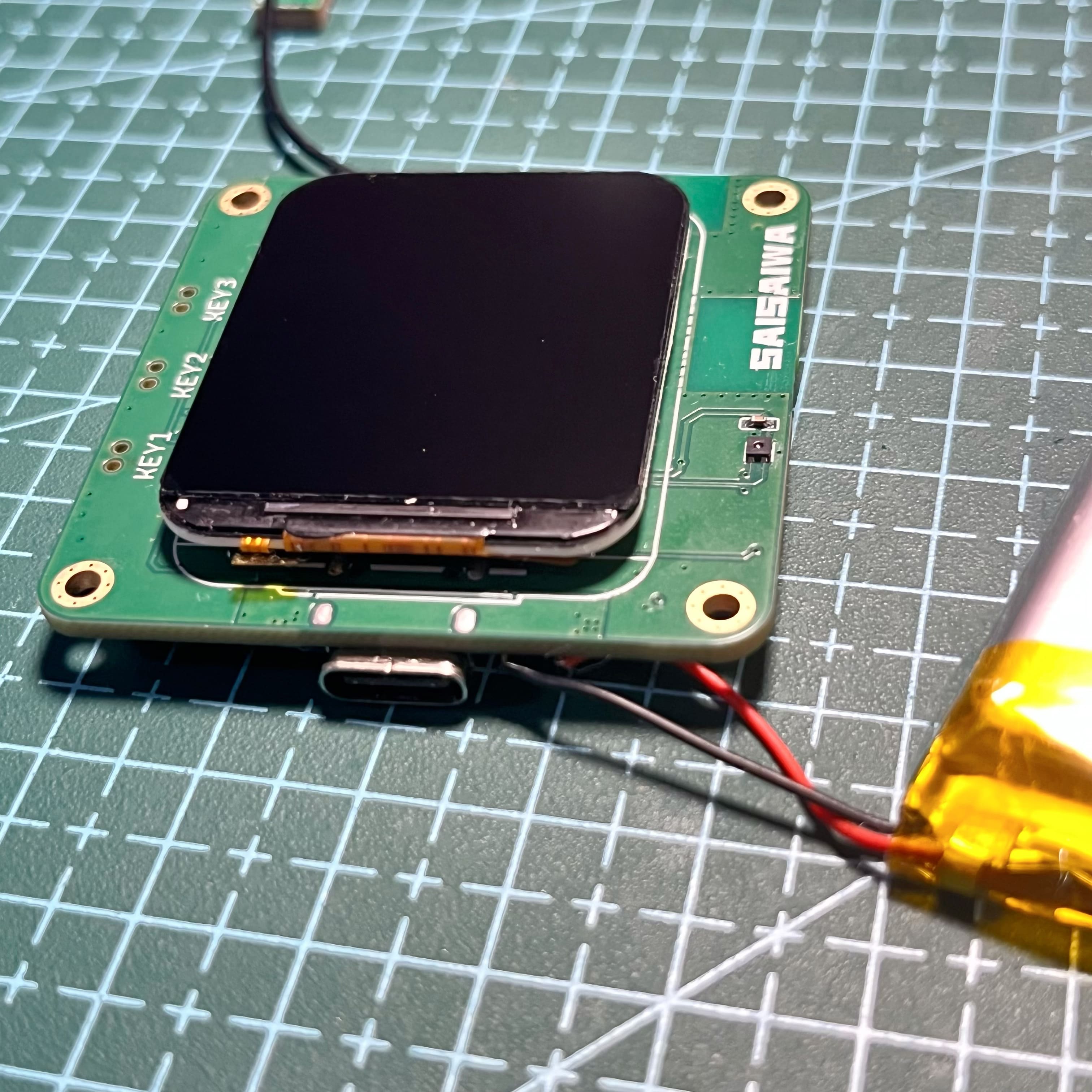
3. Image Gallery
-
3.

Source Code
Github Address: https://github.com/ccy-studio/CCY-GPS-ESP32S3.git
To pull the Git repository containing submodules, please follow these steps:
Clone the repository containing submodules:
git clone --recurse-submodules https://github.com/ccy-studio/CCY-GPS-ESP32S3.git
If you have already cloned a repository without submodules, you can run the following command to initialize and update the submodules:
git submodule update --init --recursive
If you need to update existing submodules, you can enter the submodule directory and pull the latest code:
cd path/to/submodule
git pull
4. Refer to the Simple Tutorial
https://oshwhub.com/article/tarzan-nas-lvgl9
5. Other
5.1 IDF compilation speed is very slow, but 100% CPU usage
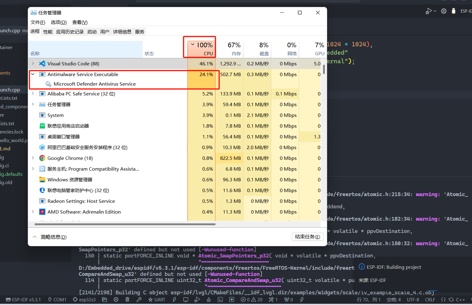
is due to Microsoft Defender. Turn off this built-in antivirus program.
5.2 Using sdkconfig.defaults
In some cases, such as sdkconfig When a file is under version control, the build system may find it inconvenient to modify the `sdkconfig` file. To avoid this, you can create an `sdkconfig.defaults` file within the build system. This file can be created manually or automatically, and the build system will never modify it. It contains all the important options that differ from the defaults and has the same format as the `sdkconfig` file. If the user remembers all the changed configurations, they can create `sdkconfig.defaults` manually or automatically by running the `idf.py save-defconfig` command.
After `sdkconfig.defaults` is created, the user can delete `sdkconfig` or add it to the ignore list of the version control system (e.g., Git's `.gitignore` file). The project build target will automatically create the `sdkconfig` file, populate the settings in the `sdkconfig.defaults` file, and configure other settings to their default values. Note that settings in `sdkconfig.defaults` will not override existing settings in `sdkconfig` during the build process. For more information, see Customizing sdkconfig Defaults.
ESP32S3 Instrument Panel (Speedometer) Version 20240916.pdf
BLJV3413_x264.mp4
PDF_GPS-ESP32S3 Instrument Panel.zip
Altium_GPS-ESP32S3 Dashboard.zip
PADS_GPS-ESP32S3 Instrument Panel.zip
BOM_GPS-ESP32S3 Dashboard.xlsx
91146
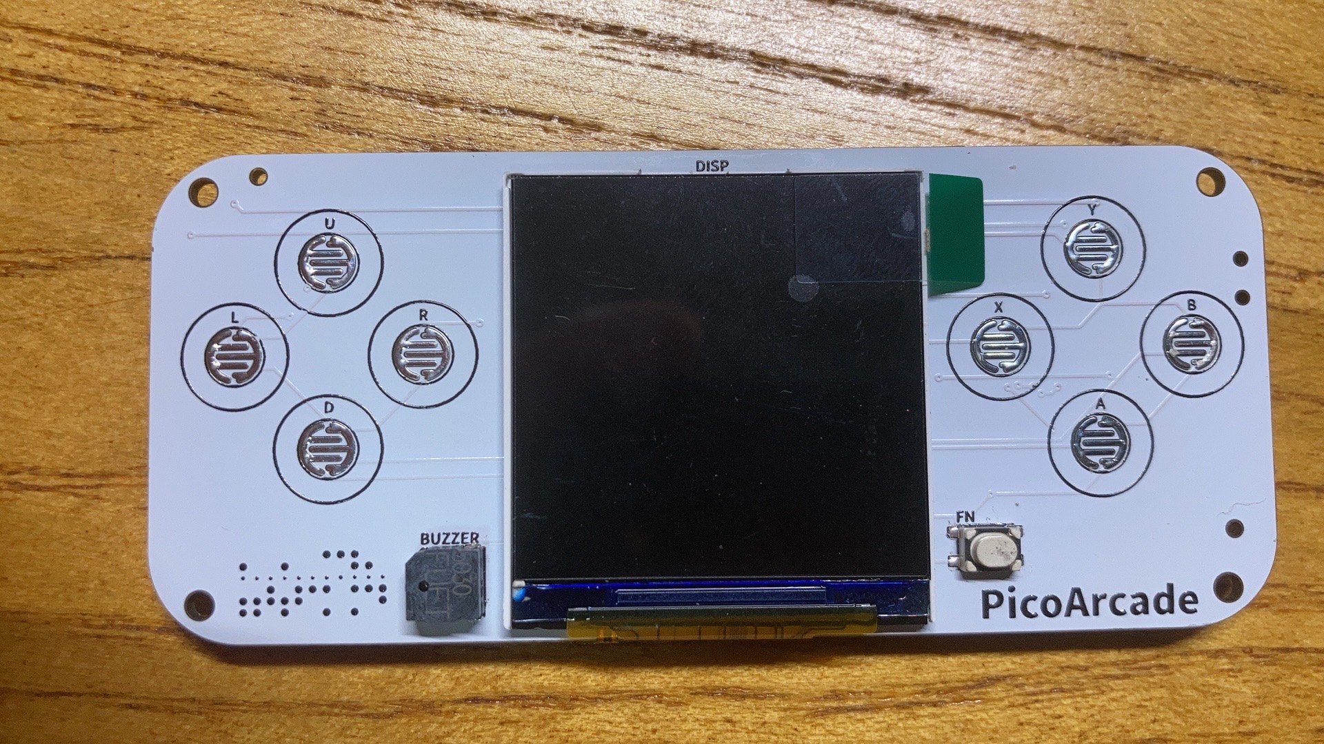
A handheld game console based on Scratch graphical programming (capable of running NES games)
Scratch Arcade is a game console designed for teenagers to program using Scratch. Unlike other MakeCode Arcade programming game consoles, it can also run NES games. For more information, please join our group and follow the education section.
The story behind this project:
I've loved playing games since childhood and have worked in game development for over ten years. Since 2018, I've been involved in Scratch programming for children, initially as a transition from game developer to children's programming educator. Through my work, I came across the open-source hardware microbit and discovered that the microbitV2 with an LCD screen could be used with the Makecode Arcade graphical tool to develop games. This graphical game programming tool allows anyone to develop their own games and download them to a game console. My first encounter with this software was quite astonishing for a traditional game developer like myself, so I immediately bought one from Taobao. After playing for a while, my professional background led me to discover some user experience issues. In Makecode Arcade, all game scenes, backgrounds, and elements are within a single main program, and the controller relies on the game console's hardware, making game programming quite difficult. Even for someone like me with years of game development experience, it felt a bit convoluted, let alone for children or beginners. Makecode Arcade still felt like a programmer doing game development. In comparison, Scratch game programming is much simpler. Common icons and sound elements can be used directly from the built-in library or uploaded from a computer, without needing to be fully programmed. Different characters can be programmed independently and modularly, and users can easily understand both the programming framework and the programming concepts. I have also verified this in actual teaching applications; the teaching difficulty of Scratch is far lower than that of Makecode Arcade.
As my work deepened, I found that most of the teaching software used by children's programming institutions in China, as well as well-known programming platforms such as Mind+, OpenBlock, and mBlock, are mostly secondary developments based on native Scratch. In the early days, almost all domestic institutions conducted children's programming teaching through Scratch, and Scratch has a relatively high penetration rate in China; many people's first lesson in children's programming is with Scratch. Makecode Arcade, on the other hand, has fewer users in China. So, I had an idea: could I develop a programming game console that can run Scratch games?
With this idea in mind, I began to make the following attempts.
My first thought was to find hardware that could directly run the native Scratch format. However, I quickly discovered a problem: native Scratch is very CPU and memory demanding. Even on a device with a configuration like a Raspberry Pi, running native Scratch wasn't very smooth. So, I considered hardware that could run Linux with a UI (such as Allwinner/RK solutions), but the minimum cost was still around 200 RMB. Clearly, this solution was like putting Scratch on a mobile device; while feasible, the hardware cost was too high, and the overall cost and advantages weren't significant. It was simpler to develop a mobile app.
I quickly conceived a second solution: instead of running the native Scratch application on the device, I would write a program similar to the one that could parse and run sb3 format, referencing the Scratch source code. However, this presented another problem. Besides the executable program, native Scratch contains many elements, icons, and other resource files, which are several tens of megabytes in size and must be pre-installed on the hardware. If the host computer adds or modifies these resource files, the slave device must upgrade its firmware to synchronize. Furthermore, it still places relatively high demands on hardware memory, and writing this software is quite difficult.
Based on the previous two rounds of consideration and discussion, I re-summarized the requirements and made some adjustments. The core requirements
are: ideally, the hardware should be the most mainstream open-source hardware currently available; the hardware BOM cost should be controlled within 100 RMB; it should be easy to manufacture and replicate; it should have strong compatibility; and it should be easy to develop firmware and expand functionality.
Additionally, people generally prefer the native Scratch UI and programming style; similar software is easy for everyone to adapt to. Therefore, we only need to maintain the Scratch programming style as much as possible. I can also do secondary development based on Scratch without changing the programming style; it seems easier to implement without insisting on running native Scratch sb3 format files.
With the previous summary, I quickly found inspiration in the microbit motherboard emulator within Makecode software. Could I treat the Scratch stage as an emulator? This way, my hardware's game running could be a hardware emulator within the Scratch software. In this way, the Scratch software would be almost identical to the native one, except for some changes to the stage.
At the time, I had a Pico:ed motherboard (based on the RP2040 controller) on hand. I created a Scratch program to simulate Pico:ed buttons and display functions.

However, since we were making a game, a screen was essential. So, I built a hardware device with an LCD screen based on the RP2040.
This project was also open-source: https://gon.gyeq.in/#/2023/0617/.
While using the RP2040 as the controller, I quickly encountered new problems. The RP2040's clock speed was only 133MHz, which struggled with image refresh. There wasn't much open-source documentation on peripheral expansion for the RP2040, making further expansion difficult. Therefore, I turned my attention to the ESP32S3, with its 240MHz clock speed, support for Wi-Fi and Bluetooth, and ample expandability.
I then rebuilt the hardware based on the ESP32S3, which

took about six months to implement the core functions. However, it still didn't feel like a game console, so I enlarged the LCD screen, reverting to the original game console design. The final product is the open-source version you see today.
Okay, actually, the entire development and verification process took a year and a half. There were many technical details and challenges involved, and it would take days and nights to write about them all. The main challenges were:
1. Ensuring the programming method remained completely compatible with native Scratch, using an emulator instead of a stage.
2. Determining how to download game resources to the game console and how to maximize the LCD refresh rate within the microcontroller to ensure smooth game execution.
3. Implementing network connectivity, recording, and sound playback on the game console.
4. The ultimate goal was to be able to open and transcode native SB3 formats.
In homage to the classic and powerful platforms Makecode Arcade and Scratch, this game console is named Scratch Arcade.
Next, we'll introduce Scratch Arcade in detail.

This is a programmable game console hardware product designed for children's programming, addressing the current limitations of Scratch teaching methods, such as monotonous program templates and lack of hardware integration, which leads to decreased student interest. This product will completely overcome these shortcomings, enhancing the richness of teaching content, the diversity and variability of programs, and significantly improving students' sense of accomplishment, all without altering existing teaching content and methods—it's completely ready to use.
Hardware Features
Hardware
Description
Chip:
ESP32-S3 Xtensa© Dual-core 240 MHz 8MB SPI flash 8MB PSRAM
Screen
: 2.0-inch 320×240 HD color screen
Network:
802.11b/g/n Wi-Fi Bluetooth 5 (LE)
Button
Programming Buttons × 9
Sound
Speaker × 1
(
100mm × 38mm
) This is the hardware configuration for the open-source version. For the educational version, click here (arcade.blockcode.fun) to view the hardware introduction.
Screen:
A large 2.0-inch TFT color screen supporting up to 65,536 rich colors (16-bit color) with a resolution of 320×240 pixels, capable of presenting a vast game stage. Combined with TileMap (coming soon), it can realize a huge 2D game world.
Network:
Powered by the powerful networking capabilities of the ESP32-S3, supporting 802.11b/g/n Wi-Fi and Bluetooth 5 (LE). Multiple consoles can also interconnect for maximum online interaction.
Interaction :
Nine buttons—eight standard game buttons (up/down/left/right/A/B/X/Y) and one function (Fn) button. Different functions can be assigned to the buttons through programming to realize various gameplay and enrich the program's interactive capabilities. Programming: Program using
graphical (Scratch) or MicroPython in BlockCode Playgrounds. The graphical (Scratch) interface is identical to Scratch, and most of the programming blocks are also the same, with only a few differences due to hardware features (the missing parts will be gradually added later to more closely resemble the original Scratch blocks and functions), making it easier for teachers familiar with Scratch to teach. The stage aspect ratio remains consistent with the original Scratch, but the resolution is reduced—320×240, with the x-coordinate changing from -160 to 160 and the y-coordinate from -120 to 120. Variables are not displayed; their content will be displayed in the newly added "Data Monitor" (stay tuned). Shapes are only available in bitmap mode; vector mode is not supported. Shapes from Scratch can be used. Backgrounds include bitmap backgrounds from Scratch, as well as TileMap backgrounds and AI backgrounds (stay tuned). TileMap backgrounds use tile maps to create a very large game map; AI backgrounds use generative AI to generate a bitmap background from text. Sound can only use WAV format audio files, with a length not exceeding 10 seconds or a size not exceeding 200kB, and must be mono. The MicroPython firmware is compiled based on MicroPython version 1.2x, adding unique packages for easier game and app development. The MicroPython programming platform is coming soon, and we also recommend using Arduino Lab for MicroPython, a lightweight MicroPython editor, for programming. Project external links : GitHub: https://github.com/BlockCodeLab/arcade-lite Gitee: https://gitee.com/blockcodelab/arcade_lite Firmware download : Download the latest version. Hold down the BOOT key (FN key) while connecting the hardware to the computer, and flash the firmware in the terminal using the following command: esptool.py --chip auto --port "serial port number" write_flash -z 0 arcade_lite.v0.9_mpy_v1.23.0.bin NES emulator: Please wait a moment. Thank you to EasyCreation Space for their production support of the educational version product. Welcome to join our group for discussion. This open-source project has undergone a year and a half of development and optimization. Its biggest achievement is validating the feasibility of the initial idea. Currently, it's just an open-source version. The educational version has many interesting and surprising features, such as voice intercom, AI, FPV image transmission remote control, and a hardware lab. However, there are still many areas that need improvement and optimization. We welcome everyone to join our group to offer suggestions and exchange ideas. Please add me on WeChat first, and I will add you to the group.

 和 图形化(右)")


scratch.mp4
nes.mp4
Scratch simulator verification.mp4
arcade_box.mp4
Online multiplayer battle.MP4
Get weather information online.MP4
arcade_lite.v0.9.build-09141500_mpy_v1.23.0.bin
PDF_Handheld Game Console Based on Scratch Graphical Programming (Can Play NES Games).zip
Altium - A handheld game console based on Scratch graphical programming (capable of running NES games).zip
PADS - A handheld game console based on Scratch graphical programming (capable of running NES games).zip
BOM_A handheld game console based on Scratch graphical programming (capable of running NES games).xlsx
91147
Hovercraft based on ESP32 and Xbox controller
The hovercraft uses an ESP32 microcontroller as the main controller and an Xbox One S controller as the remote control to send control signals to move the hovercraft. The source code is attached. For beginners only!
1. Getting Started
August 27, 2024
23:26
First, use platform to create the project shown in the image below.
Test code
void setup() {
// put your setup code here, to run once:
// Initialize serial port
Serial.begin(115200);
}
void loop() {
// put your main code here, to run repeatedly:
Serial.println("My First PIO Project!");
delay(1000);
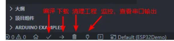
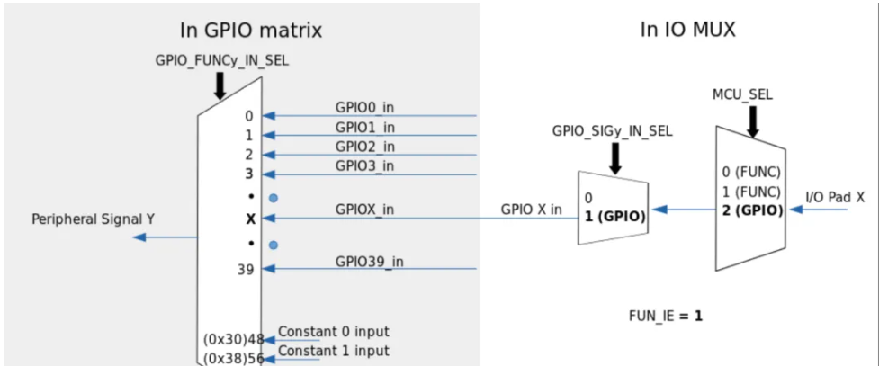
} Problems with
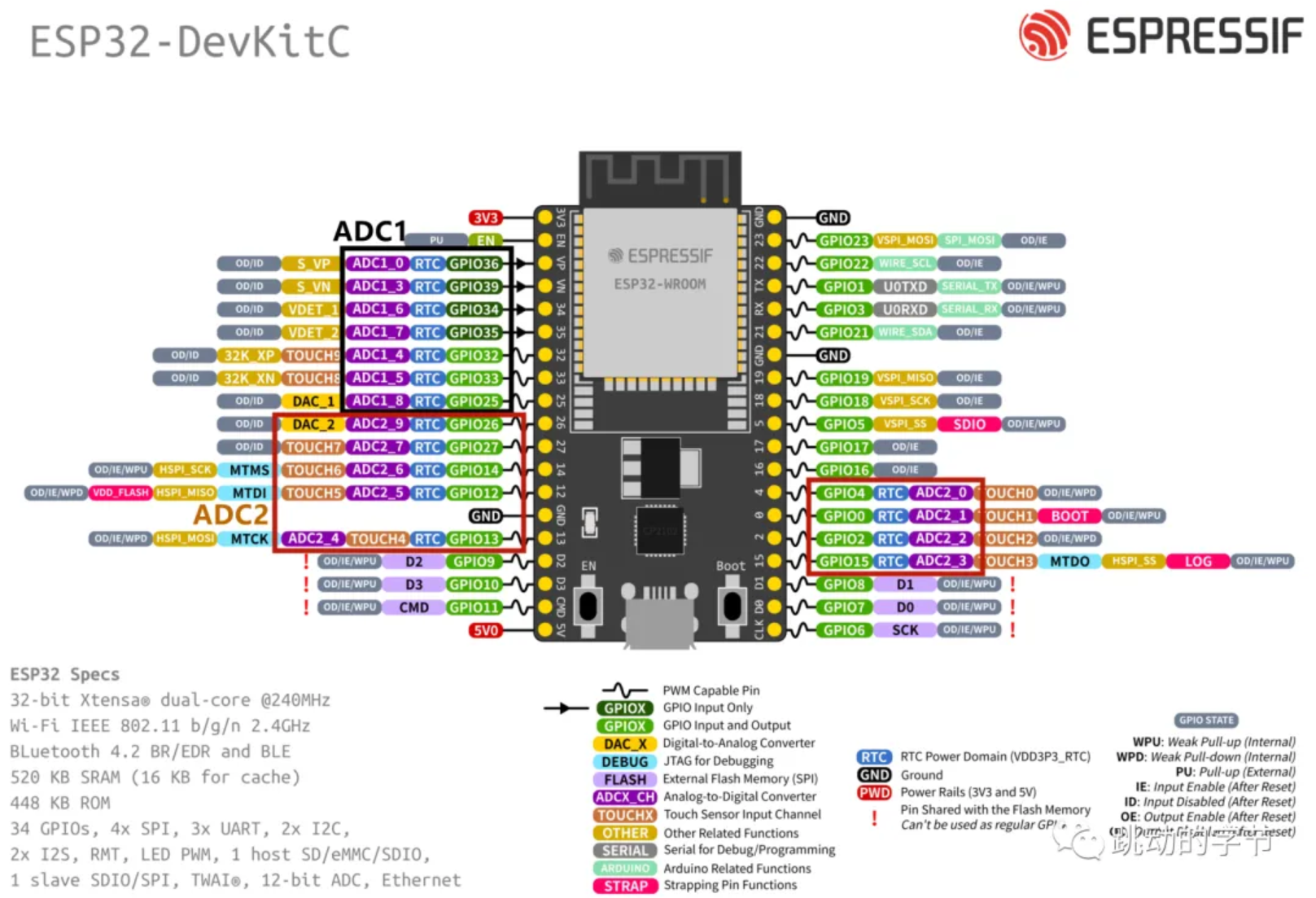
compilation and download The default baud rate of Platform is 9600. You need to add monitor_speed = 115200 to the configuration file to display it correctly. 2. Pin Level Reading and Writing August 27, 2024 23:53 Directly read the pin level #include void setup() { // put your setup code here, to run once: // Initialize serial port Serial.begin(115200); pinMode(2,OUTPUT);// Initialize io pinMode(4,INPUT);// Initialize io } void loop() { // put your main code here, to run repeatedly: // Serial.println("My First PIO Project!"); // delay(1000); digitalWrite(2,digitalRead(4));//Set the level of pin 2 to read the input level of pin 4 } Unlike the simple multiplexing of STM32, the multiplexer of ESP32 allows designers to flexibly change the internal GPIO pin connections of the chip and route them to any signal, which makes the hardware design and wiring much more convenient. #include void bt_callBack(void); void setup() { // put your setup code here, to run once: // Initialize serial port Serial.begin(115200); pinMode(2,OUTPUT);// Initialize io pinMode(4,INPUT);// Initialize io attachInterrupt(4,bt_callBack,CHANGE); } void loop() { // put your main code here, to run repeatedly: // Serial.println("My First PIO Project!"); // delay(1000); // digitalWrite(2,digitalRead(4));// Set the level of pin 2 to read the input level of pin 4 } void bt_callBack(void)// Interrupt callback function { digitalWrite(2,digitalRead(4)); } Control via interrupt 3. Serial communication August 28, 2024 0:34 ESP32 chip has 3 UARTs The interface includes UART0, UART1, and UART2, supporting asynchronous communication and IrDA, with a communication speed of up to 5Mbps. The three interfaces can be directly accessed by DMA or CPU. The three serial ports have transmit and receive FIFOs and share 1024*8bit RAM. Through the serial ports, we can easily communicate with other peripherals or print data. The default pins for UART1 are GPIO9 and GPIO10. These two interfaces are generally used to connect to external Flash memory. The program uses these two pins by default, so remember to change them to other I/O ports when using them. `Serial1.begin(115200,SERIAL_8N1,26,27); ` Serial1 can be viewed in the definition as serial port 2, so change RX to 26 and TX to 27. The first parameter is the baud rate setting; if you input 0, the baud rate will be automatically detected. The second parameter is the serial port configuration parameter; `SERIAL_8N1` means 8 data bits, no parity bit, and 1 stop bit. Common serial port functions can be found in `HardwareSerial`: `void begin(unsigned long baud, uint32_t config=SERIAL_8N1, int8_t rxPin=-1, int8_t txPin=-1, bool invert=false, unsigned long timeout_ms = 20000UL); // Serial port initialization void` end(); // Disable serial port void updateBaudRate(unsigned long baud); // Reset baud rate int available(void); // Returns data in the serial port receive buffer int read(void); // Returns one byte of data in the serial port receive buffer, then deletes this byte from the buffer void flush(void); // Waits for serial port data transmission and reception to complete size_t write(uint8_t); // Writes data to the TX buffer


`size_t setRxBufferSize(size_t);` // Sets the size of the receive buffer.
Various formatted printing methods:
`Serial.println(data)` // Outputs data from the serial port, followed by a carriage return (ASCII 13, or 'r') and a newline character (ASCII 10, or 'n'). This function returns the same value as `Serial.print()`.
`Serial.println(b)` // Outputs the ASCII value of `b` in decimal form, followed by a carriage return and a newline character. `
Serial.println(b, DEC)` // Outputs the ASCII value of `b` in decimal form, followed by a carriage return and a newline character.
`Serial.println(b, HEX)` // Outputs the ASCII value of `b` in hexadecimal form, followed by a carriage return and a newline character.
`Serial.println(b, OCT)` // Outputs the ASCII value of `b` in octal form, followed by a carriage return and a newline character.
`Serial.println(b, BIN)` // Outputs the ASCII code value of `b` in binary data format, followed by a newline character and a carriage return.
`Serial.print(b, BYTE)` // Outputs `b` as a single byte, followed by a newline character and a carriage return.
`Serial.println(str)` // If `str` is a string or array, outputs the entire ASCII code of `str`.
Serial.println() // Outputs only a newline and a carriage return character.
Use ch340 to connect RX to pin 27 and TX to pin 26 respectively.
#include
int recData = 0;
void bt_callBack(void);
void setup() {
// put your setup code here, to run once:
// Initialize serial port
Serial.begin(115200);
Serial1.begin(115200,SERIAL_8N1,26,27);
pinMode(2,OUTPUT);// Initialize io
pinMode(4,INPUT);// Initialize io
// attachInterrupt(4,bt_callBack,CHANGE);// Initialize interrupt
}
void loop() {
// put your main code here, to run repeatedly:
// Serial.println("My First PIO Project!");
// delay(1000);
// digitalWrite(2,digitalRead(4));// Set the level of pin 2 to read the input level of pin 4
if(Serial1.available()>0){
recData = Serial1.read();
Serial1.print("received: ");
Serial1.println(recData,HEX);
}
}
void bt_callBack(void)//interrupt callback function
{
digitalWrite(2,digitalRead(4));
}
Then verify the sending and receiving through the serial port assistant.

5.PWM
August 28, 2024
22:12
ESP32 Unlike ordinary PWM, it is called LED PWM here. It is mainly used to control the brightness and color of LEDs. Of course, it can also be used for other purposes. There are 16 channels in total, 8 high speed and 8 low speed. These 16 channels can be assigned to any IO (except for some that only have input functions).

The 16 channels are divided into two groups according to speed. Each group has 4 timers corresponding


 京公网安备 11010802033920号

 LTC3700EMS


