1. Getting Started
August 27, 2024
23:26
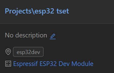
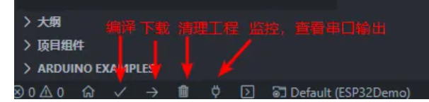
First, use platform to create the project shown in the image below.
Test code
void setup() {
// put your setup code here, to run once:
// Initialize serial port
Serial.begin(115200);
}
void loop() {
// put your main code here, to run repeatedly:
Serial.println("My First PIO Project!");
delay(1000);
} Problems with
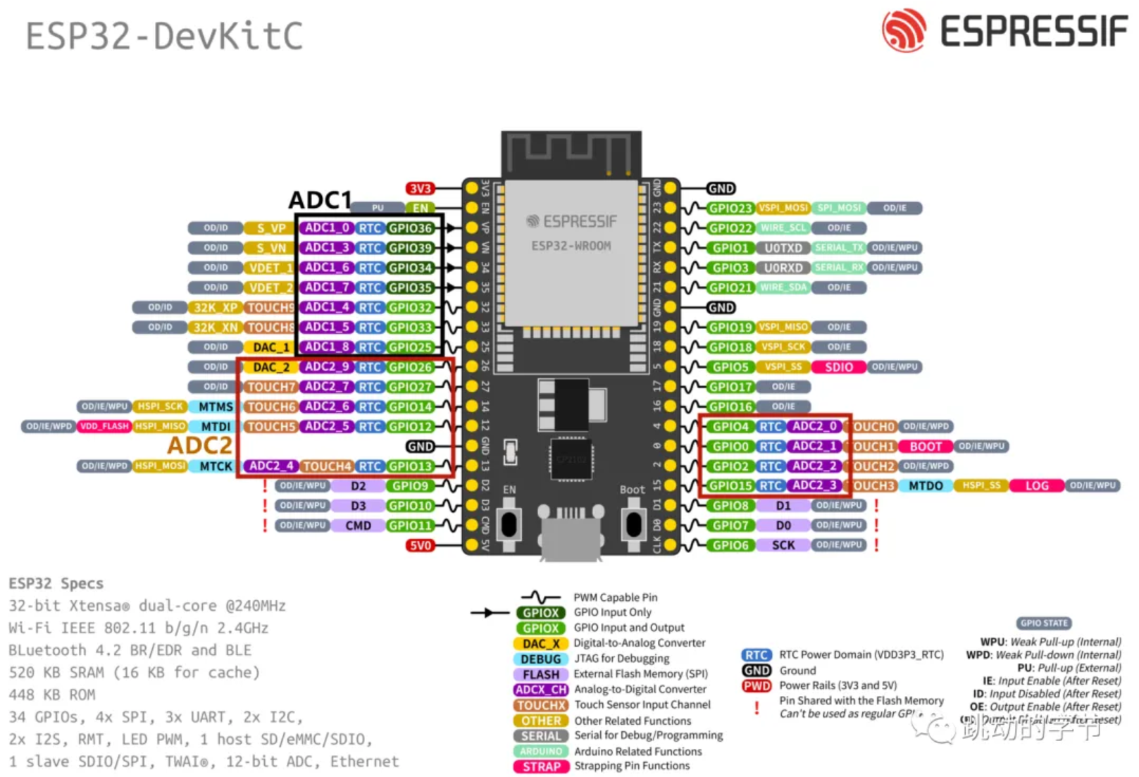
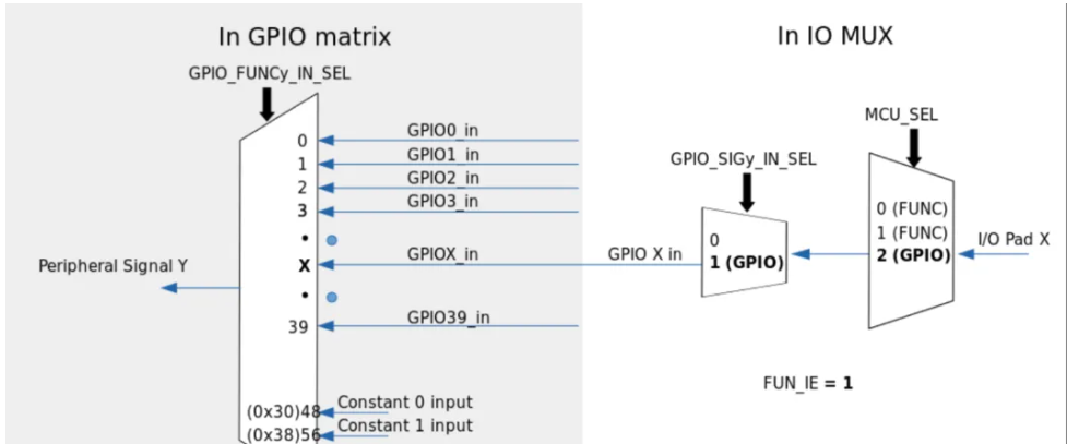
compilation and download The default baud rate of Platform is 9600. You need to add monitor_speed = 115200 to the configuration file to display it correctly. 2. Pin Level Reading and Writing August 27, 2024 23:53 Directly read the pin level #include void setup() { // put your setup code here, to run once: // Initialize serial port Serial.begin(115200); pinMode(2,OUTPUT);// Initialize io pinMode(4,INPUT);// Initialize io } void loop() { // put your main code here, to run repeatedly: // Serial.println("My First PIO Project!"); // delay(1000); digitalWrite(2,digitalRead(4));//Set the level of pin 2 to read the input level of pin 4 } Unlike the simple multiplexing of STM32, the multiplexer of ESP32 allows designers to flexibly change the internal GPIO pin connections of the chip and route them to any signal, which makes the hardware design and wiring much more convenient. #include void bt_callBack(void); void setup() { // put your setup code here, to run once: // Initialize serial port Serial.begin(115200); pinMode(2,OUTPUT);// Initialize io pinMode(4,INPUT);// Initialize io attachInterrupt(4,bt_callBack,CHANGE); } void loop() { // put your main code here, to run repeatedly: // Serial.println("My First PIO Project!"); // delay(1000); // digitalWrite(2,digitalRead(4));// Set the level of pin 2 to read the input level of pin 4 } void bt_callBack(void)// Interrupt callback function { digitalWrite(2,digitalRead(4)); } Control via interrupt 3. Serial communication August 28, 2024 0:34 ESP32 chip has 3 UARTs The interface includes UART0, UART1, and UART2, supporting asynchronous communication and IrDA, with a communication speed of up to 5Mbps. The three interfaces can be directly accessed by DMA or CPU. The three serial ports have transmit and receive FIFOs and share 1024*8bit RAM. Through the serial ports, we can easily communicate with other peripherals or print data. The default pins for UART1 are GPIO9 and GPIO10. These two interfaces are generally used to connect to external Flash memory. The program uses these two pins by default, so remember to change them to other I/O ports when using them. `Serial1.begin(115200,SERIAL_8N1,26,27); ` Serial1 can be viewed in the definition as serial port 2, so change RX to 26 and TX to 27. The first parameter is the baud rate setting; if you input 0, the baud rate will be automatically detected. The second parameter is the serial port configuration parameter; `SERIAL_8N1` means 8 data bits, no parity bit, and 1 stop bit. Common serial port functions can be found in `HardwareSerial`: `void begin(unsigned long baud, uint32_t config=SERIAL_8N1, int8_t rxPin=-1, int8_t txPin=-1, bool invert=false, unsigned long timeout_ms = 20000UL); // Serial port initialization void` end(); // Disable serial port void updateBaudRate(unsigned long baud); // Reset baud rate int available(void); // Returns data in the serial port receive buffer int read(void); // Returns one byte of data in the serial port receive buffer, then deletes this byte from the buffer void flush(void); // Waits for serial port data transmission and reception to complete size_t write(uint8_t); // Writes data to the TX buffer


`size_t setRxBufferSize(size_t);` // Sets the size of the receive buffer.
Various formatted printing methods:
`Serial.println(data)` // Outputs data from the serial port, followed by a carriage return (ASCII 13, or 'r') and a newline character (ASCII 10, or 'n'). This function returns the same value as `Serial.print()`.
`Serial.println(b)` // Outputs the ASCII value of `b` in decimal form, followed by a carriage return and a newline character. `
Serial.println(b, DEC)` // Outputs the ASCII value of `b` in decimal form, followed by a carriage return and a newline character.
`Serial.println(b, HEX)` // Outputs the ASCII value of `b` in hexadecimal form, followed by a carriage return and a newline character.
`Serial.println(b, OCT)` // Outputs the ASCII value of `b` in octal form, followed by a carriage return and a newline character.
`Serial.println(b, BIN)` // Outputs the ASCII code value of `b` in binary data format, followed by a newline character and a carriage return.
`Serial.print(b, BYTE)` // Outputs `b` as a single byte, followed by a newline character and a carriage return.
`Serial.println(str)` // If `str` is a string or array, outputs the entire ASCII code of `str`.
Serial.println() // Outputs only a newline and a carriage return character.
Use ch340 to connect RX to pin 27 and TX to pin 26 respectively.
#include
int recData = 0;
void bt_callBack(void);
void setup() {
// put your setup code here, to run once:
// Initialize serial port
Serial.begin(115200);
Serial1.begin(115200,SERIAL_8N1,26,27);
pinMode(2,OUTPUT);// Initialize io
pinMode(4,INPUT);// Initialize io
// attachInterrupt(4,bt_callBack,CHANGE);// Initialize interrupt
}
void loop() {
// put your main code here, to run repeatedly:
// Serial.println("My First PIO Project!");
// delay(1000);
// digitalWrite(2,digitalRead(4));// Set the level of pin 2 to read the input level of pin 4
if(Serial1.available()>0){
recData = Serial1.read();
Serial1.print("received: ");
Serial1.println(recData,HEX);
}
}
void bt_callBack(void)//interrupt callback function
{
digitalWrite(2,digitalRead(4));
}
Then verify the sending and receiving through the serial port assistant.

5.PWM
August 28, 2024
22:12
ESP32 Unlike ordinary PWM, it is called LED PWM here. It is mainly used to control the brightness and color of LEDs. Of course, it can also be used for other purposes. There are 16 channels in total, 8 high speed and 8 low speed. These 16 channels can be assigned to any IO (except for some that only have input functions).

The 16 channels are divided into two groups according to speed. Each group has 4 timers corresponding to 8 channels. The two channels share one timer. Therefore, a maximum of 8 different frequencies of PWM can be output.
Assign channels to GPIO pins
Determine the PWM channel to be used, PWM_Ch, and bind it to GPIO_Pin.
`ledcAttachPin(GPIO_Pin, PWM_Ch);` This function sets
the frequency and resolution
of the PWM channel. The resolution can be set from 1 bit to 16 bits. For example, setting it to 8 bits results in a duty cycle range of 0-255, and setting it to 10 bits results in 0-1023. The function is quite simple.
/*
* PWM_Ch PWM channel 0-15
* PWM_Freq PWM frequency
* PWM_Res PWM resolution 1-16 *
*/ `
ledcSetup(PWM_Ch, PWM_Freq, PWM_Res);`
Setting the duty cycle
involves directly writing the corresponding duty cycle to output PWM on the corresponding IO.
`ledcWrite(PWM_Ch, DutyCycle); ` ESP
- NOW, developed by
Espressif , is a protocol that enables multiple devices to communicate with each other without using Wi-Fi. This protocol is similar to the 2.4GHz wireless connection used in wireless mice. Therefore, pairing between devices needs to occur before they can communicate. Once paired, the connection is secure and point-to-point, requiring no handshake. Unlike persistent connections like TCP/IP, it is connectionless. If one board experiences a power outage, it will automatically reconnect and resume communication with its connected devices after restarting. Unlike the traditional OSI model, ESP-NOW removes some layers, retaining only the most basic transport layer, reducing packet loss and latency caused by network congestion and achieving faster response times. In short, ESP-NOW is a fast communication protocol that can be used to exchange short messages (maximum 250 bytes per message) between ESP32 boards. The advantages of ESP-NOW...
Fast Response: Upon power-on, the device can directly transmit data and control other paired devices without any wireless connection, with response times measured in milliseconds.
Long-Distance Communication: ESP-NOW supports long-distance communication, with its onboard antenna providing over 200 meters of range in open outdoor conditions.
Multi-Hop Control: ESP-NOW enables multi-hop control of devices, allowing control of hundreds of devices via unicast, broadcast, and group control.
New Network Configuration Method: Provides a new method in addition to Wi-Fi and Bluetooth. The first device is configured with a network via Bluetooth; other devices do not need to configure SSID/password information, and the first device connected to the network can directly send this information to other devices.
Upgrades: Suitable for firmware upgrades or large-scale data upgrades.
Debugging: In inconvenient environments such as high-temperature and high-pressure conditions, it can receive data from multiple devices for rapid fault diagnosis.
Low Cost: Coexistence with Wi-Fi and Bluetooth.
Security: ESP-NOW uses the CCMP method to protect the security of supplier-specific action frames; see IEEE Std. 802.11-2012 for details.
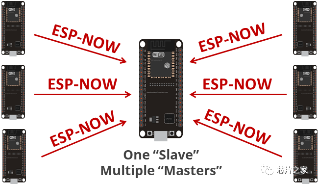
ESP-NOW communication
features unidirectional communication,
where a slave device sends data to a master device.
This is suitable for devices sending data one-way from one device to another, such as a slave device collecting sensor data or sending switch signals to a master device.

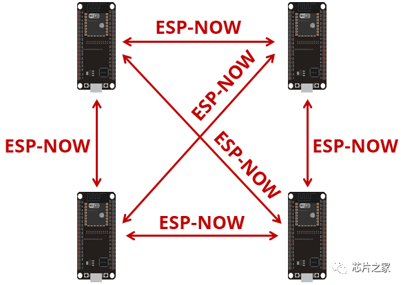
Bidirectional communication allows for communication between a master device and

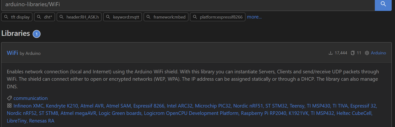
multiple slave devices , and between multiple devices. ESP-NOW is well-suited for building small networks, allowing multiple ESP32 devices to exchange data. Obtaining the board's MAC address: ESP-NOW uses the MAC address as a unique identifier for different devices, similar to an ID code. While automatic pairing via scanning is possible, for simplicity, we'll use the most basic method to obtain the host device's MAC address using the following code: #include "WiFi.h" void setup(){ Serial.begin(115200); WiFi.mode(WIFI_MODE_STA); Serial.println(WiFi.macAddress()); } void loop(){ } If the WiFi header file is missing, it needs to be manually installed in the platform. After obtaining the host's MAC address, it needs to be recorded. Initialize ESP-NOW. WiFi must be initialized before this function call. `esp_now_init(); ` Add a paired device . Call this function to pair the device, configuring MAC address, channel, encryption information, etc. `esp_now_add_peer(); ` Send data to the paired device. `esp_now_send(); ` Send data callback function . Register a function to be called when sending data; this function will return a message indicating whether the transmission was successful. `esp_now_register_send_cb(); ` Receive data callback function . Register a function to be called when data is received. esp_now_register_rcv_cb(); #include #define PWM1_Ch 0 //PWM channel 0-15 #define LED_GPIO 32 //PWM output I/O port #define PWM1_Res 10 //PWM resolution 1-16 #define PWM1_Freq 50 //PWM frequency int PWM1_DutyCycle = 0; void setup() { Serial.begin(115200); ledcAttachPin(LED_GPIO, PWM1_Ch); //Define the PWM channel of the I/O port ledcSetup(PWM1_Ch, PWM1_Freq, PWM1_Res); //Define the relevant parameters of PWM output } void loop() { //Implement the ES08 servo to rotate back and forth from 0-180 degrees while(PWM1_DutyCycle //Set the PWM transformation conditions. Here, I am based on the ES08II servo, 10 resolution, full count 1024 { //The servo's duty cycle from 0.5ms to 2.5ms is the percentage of 20ms. Multiplying the 0.5ms percentage of 20ms by 1024 gives the servo duty cycle at 0 degrees. ledcWrite(PWM1_Ch, PWM1_DutyCycle++); delay(10); } while(PWM1_DutyCycle > 25) { ledcWrite(PWM1_Ch, PWM1_DutyCycle--); delay(10); } }


 京公网安备 11010802033920号

 2200AGF1502224A


