This digital voltmeter and ammeter is based on the LCSC Diwenxing CW32F030C8T6 development board.
This project originates from the LCSC development board voltmeter and ammeter training camp, with some simplifications in functionality and design.
I. Functionality
: Only two functions are retained:
1. Voltage measurement (0-30V)
2. Current measurement (0-3A).
The measurement method borrows from a multimeter, using positive and negative probes connected across the circuit being measured.
II. Schematic Design:
To accelerate development, this project uses the LCSC Diwenxing development board. Therefore, the core task becomes how to use the ADC pins provided by the MCU to measure voltage. The main design ideas are as follows:
1. Since the development board already includes a complete LDO circuit, this part of the circuit is omitted in the schematic. The advantage is that it greatly reduces the number of components in the BOM. The inconvenience is that the development board must be powered during measurement. Since the core requirement of this project is voltage and current measurement, rather than the design of peripheral circuits, this was chosen to be omitted.
2. The external interface design also follows a minimalist principle, retaining only two probe sockets and a slide switch. This design is based on the desire to create a simple tool, and simple tools typically have a concise design for ease of use. The
entire schematic includes the following parts:
1. Development board interface: Connects to the LCSC/Diwenxing development board via two 20-pin female connectors. The voltage required for the sampling circuit clamping is obtained from the development board's 3.3V port.
2. Voltage and current sampling section: This section uses the same components as the training camp, aiming to examine the sampling accuracy of the CW32F030 MCU's native ADC. Voltage and current are switched via the SW1 slide switch. This saves a digital display.
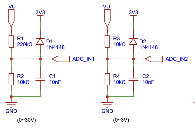
Voltage measurement is performed using a resistor divider, with an appropriate voltage division ratio designed according to the measurement range. Furthermore, a diode (1N4148) clamping mechanism controls the voltage entering the MCU pins within a safe range.
In selecting the two voltage measurement values (program-controlled), when the measured result is greater than 3V, the value of the ADC_IN1 pin is selected. If it is less than or equal to 3V, the result of the ADC_IN2 pin is automatically selected for display to improve measurement accuracy.
This design uses the 3.3V clamping voltage provided by the development board. The voltage drop of the 1N4148 is typically 1V, so theoretically, the current entering the MCU pin should be below 4.3V. Referring to the CW32F030 datasheet, the maximum voltage of the IO port is Vdd + 0.3V, approximately 6.3V. (If you want to replicate and perform high-voltage measurements, ensure that the highest voltage at the ADC_IN2 point does not exceed 6V, otherwise it may damage the MCU pin).

The current sampling resistor is a 100mΩ, 1W package, consistent with the training camp specifications. Based on the actual current measurement results, this part has considerable room for optimization. For example, a more professional sampling resistor could be selected, or an amplifier circuit could be used.
3. LED digital tube section: used to display the measured voltage or current values. The MCU's GPIO ports are directly connected to the digital tube. Different numbers are displayed by controlling the high and low levels of the GPIO ports.
III. PCB Design:
Due to the relatively simple circuit, PCB routing is not difficult. It is important to note that the current sampling circuit needs to consider the throughput of 3A current. Additionally, suitable surface-mount components can be selected for the sampling circuit to further improve the aesthetics of the layout.
IV. Code:
The user code logic is as follows:
1. Initialize the development board clock (board.c).
2. Configure the LED digital tube (display.c).
3. Configure the acquisition IO ports (measure.c).
4. Configure the timer and complete the interrupt handling logic (interrupts.c): process the data acquired from the three acquisition ports every 1ms. When switching to the voltage measurement circuit, ADC_IN1 and ADC_IN2 ports have values. If the voltage of ADC_IN1 is greater than 3, that value is used for display. Otherwise, the data from ADC_IN2 is used. When switching to the current measurement circuit, theoretically, the readings of ADC_IN1 and ADC_IN2 should be 0. At this point, it is determined that a circuit measurement is being performed, and the data from the ADC_IN3 port is used for display.
V. Materials
All components in this project are from LCSC, except for the following:
1. Multimeter probes
2. Multimeter probe socket
VI. Assembly Instructions
1. The purchased multimeter probe socket is relatively tall. To minimize the overall height of the project's casing (currently designed to be 25mm), the screws at the bottom of the socket need to be shortened (I used a hacksaw). If you want to replicate it, you can look for a shorter socket.
2. Connect the leads from the probe socket to the CN1 pin header via connectors.
3. Secure the upper casing with four M2 screws. If you want to replicate it, please consider the PCB board fixing (you can add stiffeners to the four corners of the lower casing and use them in conjunction with the four studs on the upper casing to press the PCB firmly). Additionally, you need to pre-tap the screws on the upper casing or pre-embed nuts.


 京公网安备 11010802033920号

 111-318-65L-P30-B12


