The
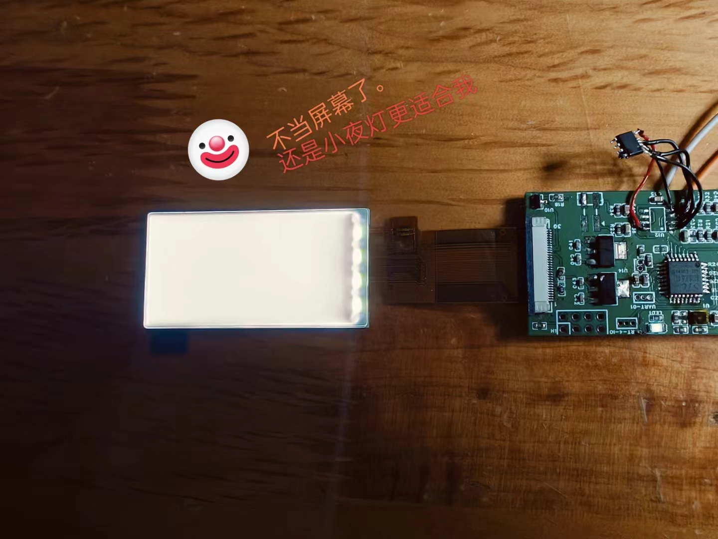
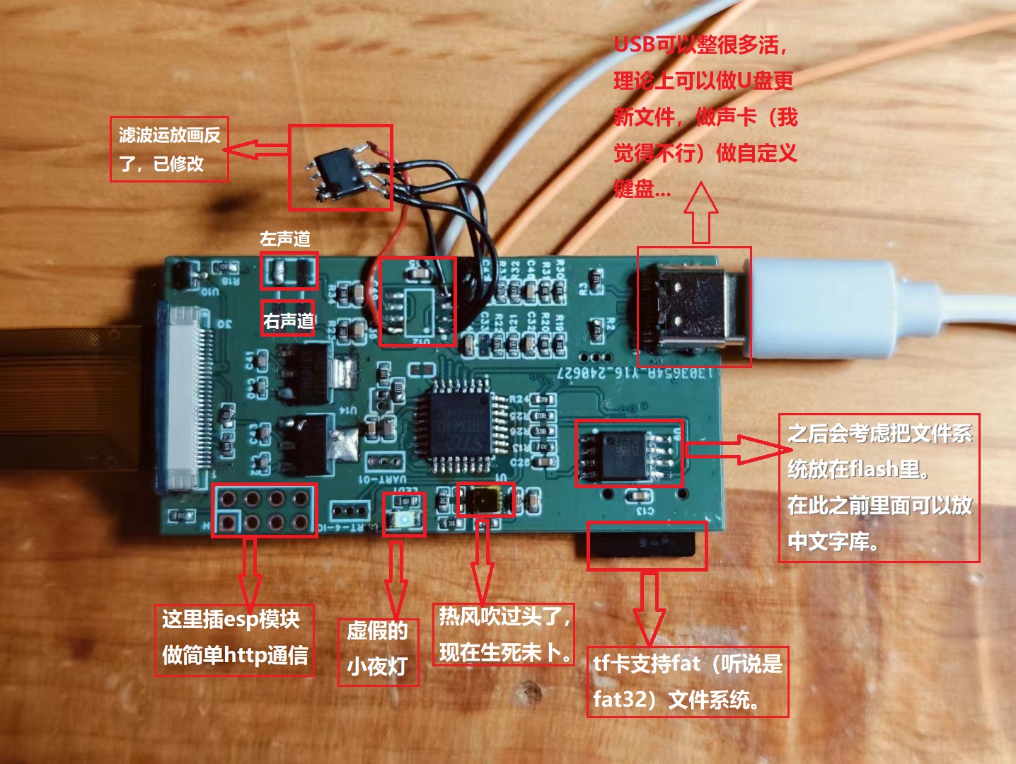
original concept for this project was a "subway station sign night light," which would save images and WAV audio effects to the onboard NOR flash memory via an STC microcontroller's USB flash drive.
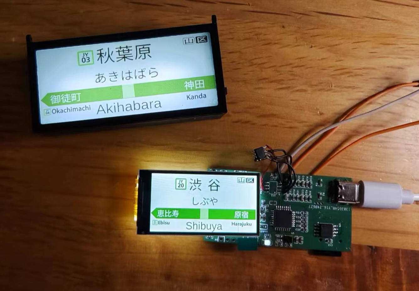
A top button would switch the images on the screen and play corresponding audio effects to simulate a subway station environment. This involved image display, simple WAV decoding, STC USB flash drive mode, flash storage, and a FAT file system.
Now, an ESP8266 module and a temperature sensor have been added to enable it to function as a desktop "mini-TV," displaying real-time weather, temperature, humidity, and time. Initially, the project aimed to add a night light function, hence the name "Multi-Function Night Light."
However , the onboard white LED lighting was very limited, and the screen backlight wasn't shielded (it was purchased online). Making the casing white and translucent... Ultimately , the project was a derivative of a "JR station sign," intended to use the screen for easy image replacement and the addition of a departure bell sound. However, to pass approval, the circuit complexity was increased, and the final result... well, it's uncertain what the final product will be. An electronic station sign? Night light? "Multimedia" development board? Other: 1. The status of the SHT30 temperature sensor is still unclear. 2. The extent of STC's USB functionality is still unclear. 3. Main function description.


PDF "Multi-functional Night Light.zip"
Altium Multifunctional Night Light.zip
PADS Multi-Function Night Light.zip
BOM_"Multi-functional Night Light".xlsx
91234
Thermocouple temperature calibrator
I recently made a thermocouple thermometer with a maximum temperature range of 1024 degrees Celsius in my spare time. Although it's called a thermometer, it's more like a development tool for learning. The code is extremely simple, and you can customize it to your needs, making whatever functions you require yourself.
The problem requires
a thermocouple thermometer with an extreme temperature measurement capability of 1024℃.
Analysis:
I recently made a thermocouple thermometer with an extreme temperature measurement capability of 1024℃ in my spare time. Although it's called a thermometer, it's more like a development tool for learning. The code is extremely simple, and you can develop it according to your own needs. You can create whatever functions you need yourself; it can function as a thermometer or an alarm clock. The files are being organized and will be open-sourced on the LCSC open-source platform later. Everyone can replicate it. I've made five so far, and they will be available on Xiaohuangyu (a second-hand marketplace). If you're interested, come and join! For communication, contact me here: QQ 493952442.
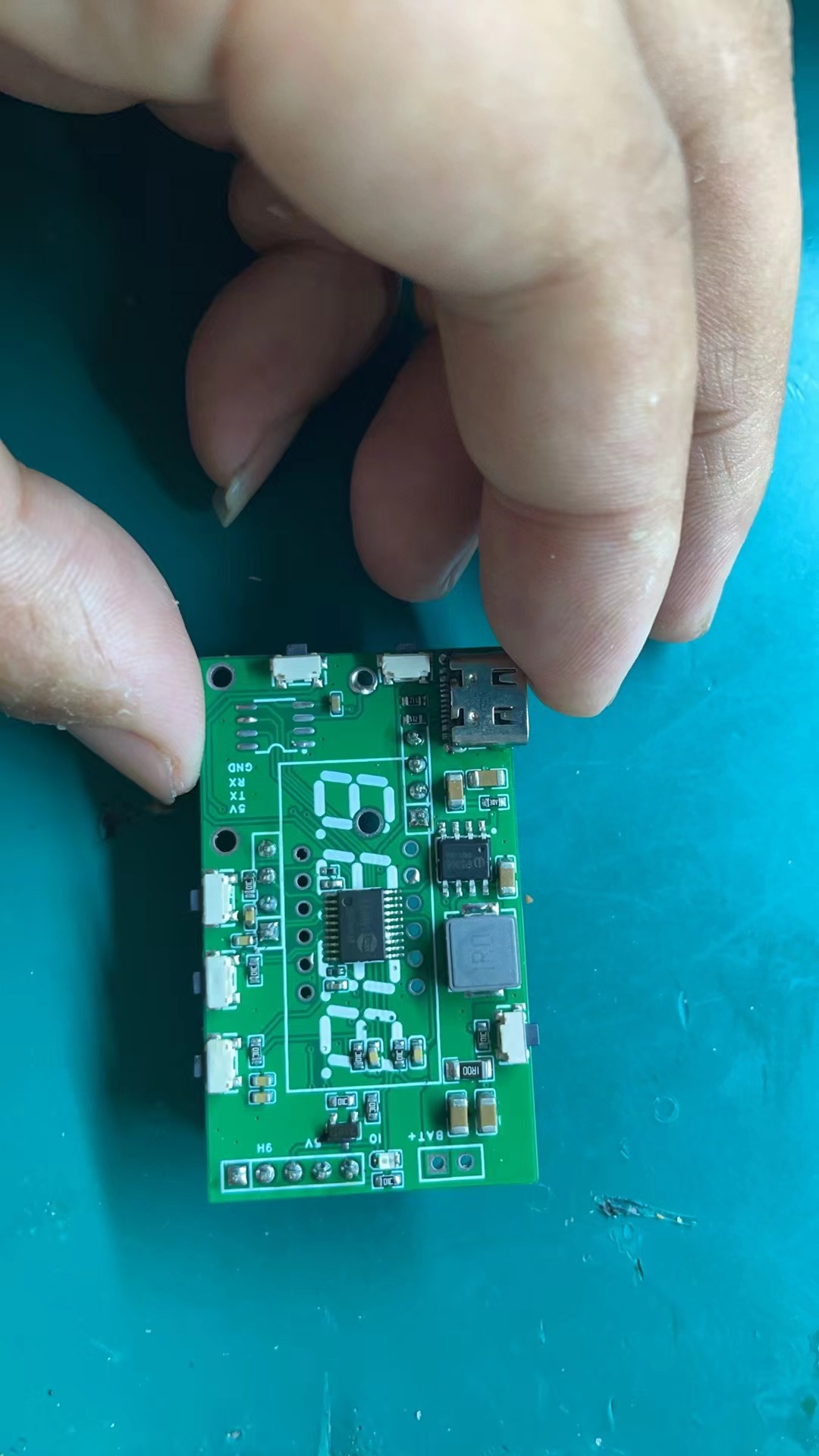
Schematic design description:
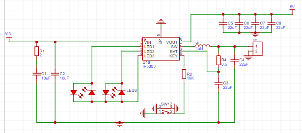
Charge and discharge using an IP5306 single-cell lithium battery. The chip charges the battery and simultaneously boosts the lithium battery voltage from 3.7V to 5V, stabilizing it to power the microcontroller and digital tube chip. Its main functions are voltage stabilization and lithium battery charge/discharge management. It can provide the microcontroller with a continuous output capacity of up to 2A, and the machine also has a 5V interface that, with the right program, can drive peripheral devices with a voltage of 5V 1.5A or less, eliminating the need for separate power supplies for these devices.

The Hezhou Air001 is a TSSOP20 packaged MCU using a high-performance 32-bit ARM® Cortex®-M0+ core, with 32Kbytes of Flash and 4Kbytes of RAM. The chip integrates multiple USART, IIC, SPI, and other communication peripherals, five 16-bit timers, one 12-bit ADC, and two comparators.

The TM1637 is controlled by a microcontroller to drive four common-anode diodes. Why not use I/O ports to drive transistors to control the digital tube? It's for beginners. With this chip, you only need to input data via DIO and CLK, without worrying about array issues. Furthermore, brightness doesn't need to be controlled manually with PWM; simply output data to the TM1637 for control—it's very simple.
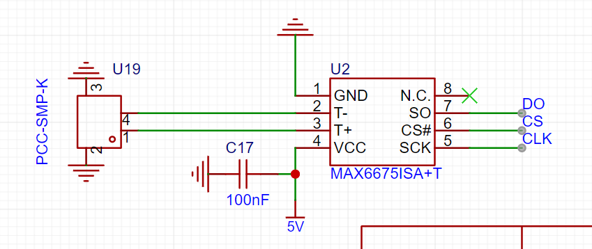
The MAX6675 internally has a signal conditioning amplifier that converts thermocouple signals into voltages compatible with the ADC input channel. The T and T- inputs are connected to a low-noise amplifier A1 to ensure high-precision input detection and isolate the thermocouple connection wires from interference sources. The thermoelectric potential output by the thermocouple is amplified by the low-noise amplifier A1, buffered by the voltage follower A2, and then sent to the ADC input.
The PCB design documentation for converting temperature and voltage values into equivalent temperature values
still needs optimization. However, the current version works normally; it can be used directly after board fabrication. The
software
code can be copied and pasted directly, but the corresponding library file needs to be downloaded. Without the library file, it will not run properly.
#include
#include
#include
// Define the pins for the digital tube connection
#define CLK PA7
#define DIO PA1
// Create a TM1637Display instance
TM1637Display display(CLK, DIO);
// MAX6675 pin definitions
#define MAX6675_CLK PB1
#define MAX6675_CS PB2
#define MAX6675_DO PB0
// Button pin definitions
#define SET_BUTTON PA5
#define INC_BUTTON PF0
#define DEC_BUTTON PF1
// Output pin definitions
#define OUTPUT_PIN PA0
MAX6675 thermocouple(MAX6675_CLK, MAX6675_CS, MAX6675_DO);
bool isSettingMode = false;
unsigned long lastBlinkTime = 0;
bool blinkState = false;
int setTemperature = 0;
const int minTemp = 0; // Minimum set temperature
const int maxTemp = 300; // Maximum set temperature
const unsigned long debounceDelay = 50; // Debounce delay
const unsigned long longPressDelay = 1000; // Long press detection delay
void setup() {
// Initialize digital tube
display.setBrightness(0x0f); // Set brightness, value range is 0-0x0f
// Initialize button input
pinMode(SET_BUTTON, INPUT_PULLUP);
pinMode(INC_BUTTON, INPUT_PULLUP);
pinMode(DEC_BUTTON, INPUT_PULLUP);
// Initialize output pin
pinMode(OUTPUT_PIN, OUTPUT);
// Read the set temperature from EEPROM
setTemperature = EEPROM.read(0); // Read the set temperature from address 0
// If the value in EEPROM is the initial value (255), then set the initial set temperature to 50
if (setTemperature == 255) {
setTemperature = 50;
saveSetTemperature(); // Save the initial set temperature to EEPROM
}
}
void loop() {
static unsigned long setButtonPressTime = 0;
// Check if the set button is long-pressed
if (digitalRead(SET_BUTTON) == LOW) {
if (setButtonPressTime == 0) {
setButtonPressTime = millis();
} else if (millis() - setButtonPressTime > longPressDelay) {
isSettingMode = !isSettingMode; // Switch mode
setButtonPressTime = 0; // Reset timer
}
} else {
setButtonPressTime = 0;
}
if (isSettingMode) {
// Display set temperature
display.showNumberDec(setTemperature);
// Increase temperature setting
if (digitalRead(INC_BUTTON) == LOW) {
delay(debounceDelay); // Debounce delay
if (digitalRead(INC_BUTTON) == LOW && setTemperature < maxTemp) {
setTemperature++;
saveSetTemperature(); // Save set temperature to EEPROM
delay(30); // Prevent continuous triggering
}
}
// Decrease temperature setting
if (digitalRead(DEC_BUTTON) == LOW) {
delay(debounceDelay); // Debounce delay
if (digitalRead(DEC_BUTTON) == LOW && setTemperature > minTemp) {
setTemperature--;
saveSetTemperature(); // Save the set temperature to EEPROM
delay(30); // Prevent continuous triggering
}
}
} else {
// Read the temperature
double temperature = thermocouple.readCelsius();
// Display the temperature
displayTemperature(temperature);
// Compare the actual temperature with the set temperature
if (temperature >= setTemperature) {
digitalWrite(OUTPUT_PIN, HIGH);
} else {
digitalWrite(OUTPUT_PIN, LOW);
}
// Wait for a period of time
delay(200);
}
}
void displayTemperature(double temp) {
// Convert the temperature value to an integer
int tempInt = int(temp);
// Display the temperature value on the digital tube
display.showNumberDec(tempInt);
}
void saveSetTemperature() {
EEPROM.write(0, setTemperature); // Write the set temperature to address 0
EEPROM.update(0, setTemperature); // Update EEPROM data
}
Physical demonstration, instructions, and
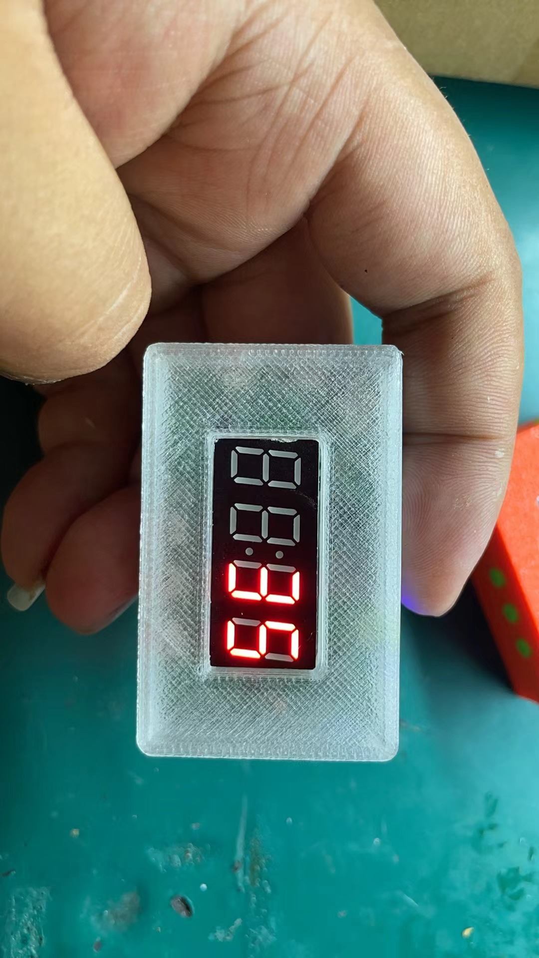

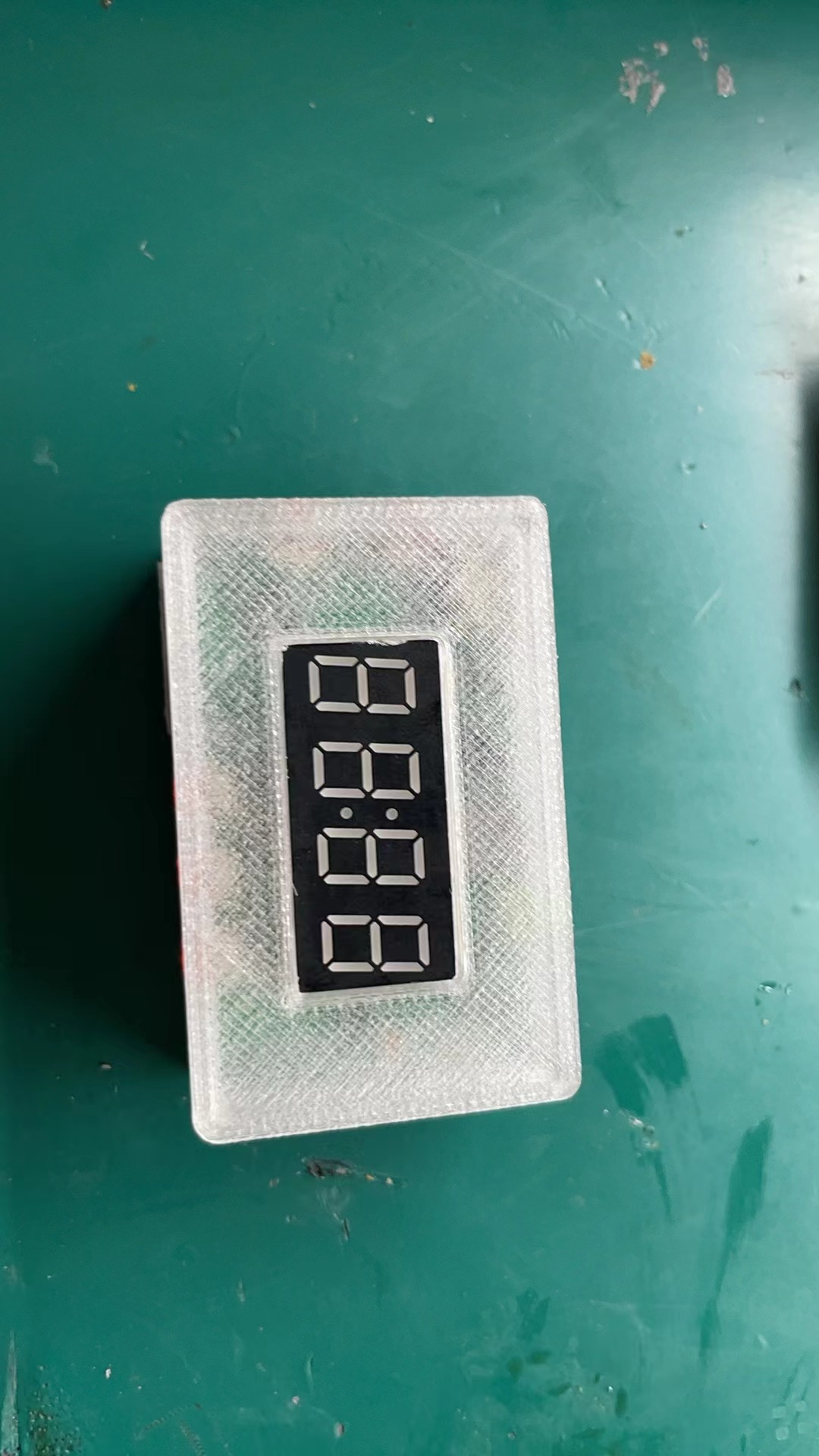
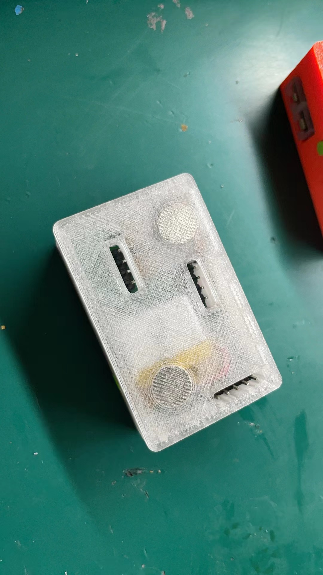
precautions :
Note the battery size. I bought this one from this brand; I don't know about other brands.
Demo video:
[Extreme Temperature Measurement 1024℃ (Open Source Thermometer) - Bilibili] https://b23.tv/mNy7Age
For any questions about replicating, you can join the group for discussion: 493952442
Note: Entries participating in the event must upload the relevant program attachments to the open source platform or personal code storage cloud. The maximum upload size for attachments is 50MB (please do not upload to the LCSC workspace, as there are limitations).
Thermocouple thermometer. 7z
PDF_Thermocouple Temperature Calibrator.zip
Altium Thermocouple Temperature Calibrator.zip
PADS_Thermocouple Temperature Calibrator.zip
BOM_Thermocouple Temperature Calibrator.xlsx
91235
WALLE Circuit Board
WALLE circuit board
Core Components: ESP32 Microcontroller: As the brain of the circuit board, the ESP32 provides powerful processing capabilities and wireless communication functions. It supports Wi-Fi and Bluetooth connectivity, enabling the circuit board to easily connect to the internet for remote control and data transmission. Arduino Compatibility: The circuit board is designed to be compatible with the Arduino development environment, meaning users can leverage the rich Arduino library and community resources to quickly develop and deploy various applications.
Features:
Precise Control: The circuit board can precisely control the robot's movement, including speed, direction, and posture, ensuring accuracy and stability when the robot performs tasks.
Multi-Sensor Support: The circuit board has reserved multiple GPIO interfaces, supporting the connection of various sensors, such as temperature sensors, for environmental perception and data collection.
Wireless Communication: Through built-in Wi-Fi and Bluetooth modules, the circuit board can achieve wireless connectivity with smartphones, tablets, or other devices, facilitating remote operation and monitoring.
Expandability: The circuit board design considers future expansion needs, providing additional interfaces and space so users can add more functional modules according to project requirements.
Overview
:
Those who watched the movie "WALL-E" in their childhood must have dreamed of owning their own WALL-E. This tutorial will guide you through building your own WALL-E robot, starting with the materials and control program you need. I think no boy can resist this little robot toy that integrates sound, light, electricity, and movement. Make one with your child during winter break, and the neighbor's kid will be green with envy!
Bill of Materials (BOM) |
Item No. | Module
|
Function |
Quantity
| Reference Price (Unit Price) |
Reference Price (Total Price) |
Remarks | |--- |---|---|---|---|---|
| 1
| Arduino UNO R3 Development Board |
Main Control Chip |
1
| 16.4
| 16.4 |
| 2 |
ESP32 C3 Development Board
| MQTT Protocol | Server Connection |
1
| 9.9
| 9.9 | |
3 |
L298N Dual H-Bridge Motor Driver Board | Drives
Track Motor |
1
| 6.4
| 6.4 | |
4
| PCA9685 16-Channel Servo Driver Board | Servo Driver | 1 | 12.5 | 12.5 | | 5 | Portable WIFI | Provides WIFI | 1 | 15 | 15 | | 6 | DC-DC 12V to 5V DC Step-Down Module | 12V to 5V Power Supply | 1 | 5.9 | 5.9 | | 7 | 12V 370 Off-Shaft Gear Motor | 107 rpm | Drives Track | 2 | 15 | 30 | Note: Buy the off-shaft version, not the center-shaft version. | | 8 | 18650 Battery Box (3 cells) | Battery Compartment | 1 | 1.2 | 1.2 9 18650 batteries in series to provide 12V power 3 8 24 10 18650 charger 1 10 10 11 SG90 9g servo motor to drive the joint 7 3.79 26.53 12 DC power plug 5.5mm (male) battery compartment power output connector 2 0.3 0.6 13 PETG-ECO black printed track and motor mount 1 35 35 The actual total weight is about 1.2kg, a rough estimate, not specifically calculated 14 PETG-ECO gray printed Wale head 1 35 35 15 PETG-ECO Caterpillar yellow printed Wale body 1 35 35 16 ASR PRO voice module (with speaker) voice recognition 1 28.9 28.9 voice control (optional) 17 1.3-inch TFT color screen weather clock screen 1 12.9 12.9 weather clock (optional) 18 ESP8266 Development Board Weather Clock Control Chip 1 13.3 13.3 Weather Clock Usage (Optional) 19 5V Laser Module Eye 1 0.65 0.65 Optional 20 WIFI Camera Network Transmission Video 1 20 20
Optional
21
Mini MP3 Player
for playing music
1
3.8
3.8
Optional
22
MFRC-522 RFID Module
NFC Wireless Identification
1
3.9
3.9
Optional
23
DHT11 Temperature Sensor
for measuring temperature
1
2.5
2.5
Optional
24
Boat-shaped
Power Switch
1
0.5
0.5
Optional
25
3W 8R Speaker
for playing music
1
4.2
4.2
Optional
26
1u2g Cloud Server
MQTT Server, Deploy H5 Control Page
1
69
69
Optional
27
Acrylic Paint (12 types in a box) for
Walle Coloring
1
1.8
1.8
Optional
Total
424.88
If you only want to complete the basic functions and realize the movement of the tracked chassis and joint movement, the hardware cost is about 160 yuan. The expansion modules can be purchased selectively according to your needs.
The following are some essential tools and common small items for DIY (not included in this list): Item
No.
Tool & Item Name
1
Hot Glue Gun
2
Multimeter
3
Soldering Iron
4
Pliers
5
TF Card, Card Reader
6 Paper
Clip
7 M3 Studs & Nuts 8 502 Glue 9 DuPont Wires (Male to Female, Female to Female) Technology Stack Used or Involved Arduino IDE Development Environment Element Plus + Vue3 + Vite + TypeScript Self-built H5 Control Page Linux + Nginx + Docker + EMQX Backend Server I. Web Control Terminal 1.1 Setting up the Arduino IDE Development Environment Arduino Official Website https://www.arduino.cc/ Arduino Chinese Community https://arduino.me/ Installing Arduino Software Installation Tutorial provided by the Chinese Community https://arduino.me/s/arduino-getting-started?aid=125 Adding a Development Board Manager File -> Preferences -> Other Development Board Managers Address Enter the following link: The following is the index provided by the Arduino Chinese Community. It will be faster than downloading from GitHub, which may encounter download failures. 12 http://arduino.me/packages/esp8266.json https://arduino.me/packages/esp32.json 3. If online installation of the Blinker library fails, try the offline installation package: https://www.diandeng.tech/doc/getting-start-esp32-wifi Blinker homepage: https://www.diandeng.tech/home The latest support package can be downloaded from the Blinker GitHub repository: https://github.com/blinker-iot The installation package provided by the Blinker official website: https://www.diandeng.tech/sdk/blinker-library-0.3.10230510.zip 4. Install the ESP32 and ESP8266 development board libraries. Simply click the corresponding library's exe file to install. 5. Install the USB serial port driver. This depends on the model of the chip downloaded to your development board. For example, the ESP32 from Heze... C3 requires the CH343 driver to be installed. Commonly used chips include CH34X and CP21XX. These two are shared in the file. If you don't have them, please search for the serial port chip model of your development board, download the corresponding driver, and install it. 1.2 Using the Blinker App as the control terminal , create a new independent Blinker device and copy the device key to replace the Blinker device key in the code. 12 // Blinker device key char auth[] = "xxxxxxxx"; Update the Blinker App's interface configuration for the Walle device, using the following code to replace it. Walle interface configuration code: 12
{¨version¨¨2.0.0¨¨config¨{¨headerColor¨¨transparent¨¨headerStyle¨¨dark¨¨background¨{¨img¨¨assets/img/headerbg.jpg¨¨isFull¨«}}¨dashboard¨|{¨type¨¨tex¨¨t0¨¨blinker introductory example¨¨t1¨¨text2¨¨bg¨Ë¨ico¨´´¨cols¨Í¨rows¨Ê¨key¨¨tex-272¨´x´É´y´É¨speech¨|÷¨lstyle¨Ê¨clr¨¨#FFF¨}{ßC¨btn¨ßJ¨fas fa-arrow-alt-down¨¨mode¨ÉßE¨back¨ßGßHßIÉßKËßLËßM¨btn-back¨´x´Ì´y´¤FßPÉßQ¨#076EEF¨}{ßCßSßJ¨fas fa-arrow-alt-up¨ßUÉßE¨forward¨ßGßHßIÉßKËßLËßM¨btn-go¨´x´Ì´y´¤BßQßXßPÉ}{ßCßSßJ¨fal fa-power-off¨ßUÉßE¨emergency stop¨ßGßHßIÉßKËßLËßM¨btn-stop¨´x´Ì´y´¤DßQ¨#EA0909¨ßPÉ}{ßCßSßJ¨fas fa-arrow-alt-right¨ßUÉßE¨right¨ßGßHßIÉßKËßLËßM¨btn-right¨´x´Î´y´¤DßPÉßQßX}{ßCßSßJ¨fas fa-arrow-alt-left¨ßUÉßE¨left¨ßGßHßIÉßKËßLËßM¨btn-left¨´x´Ê´y´¤DßQßXßPÉ}{ßCßSßJ¨fad fa-arrow-alt-circle-up¨ßUÉßE¨raise neck¨ßGßHßIÉßKËßLËßM¨btn-nick-up¨´x´Ì´y´ÏßQ¨#FBA613¨}{ßCßSßJ¨fad fa-arrow-alt-circle-down¨ßUÉßE¨lower neck¨ßGßHßIÉßKËßLËßM¨btn-nick-down¨´x´Ì´y´ÑßQßoßPÉ}{ßCßSßJ¨fad fa-arrow-alt-up¨ßUÉßE¨left hand¨ßGßHßIÉßKËßLËßM¨btn-left-hand-up¨´x´É´y´ÒßQ¨#00A90C¨ßPÉ}{ßCßSßJßsßUÉßE¨right hand¨ßGßHßIÉßKËßLËßM¨btn-right-hand-up¨´x´Ï´y´ÒßQßv}{ßCßSßJ¨fad fa-arrow-alt-down¨ßUÉßE¨Left hand down¨ßGßHßIÉßKËßLËßM¨btn-left-hand-down¨´x´É´y´¤BßPÉßQßv}{ßCßSßJßyßUÉßE¨Right hand down¨ßGßHßIÉßKËßLËßM¨btn-right-hand-down¨´x´Ï´y´¤BßQßv}{ßCßSßJ¨fad fa-arrow-alt-circle-left¨ßUÉßE¨Turn left head¨ßGßHßIÉßKËßLËßM¨btn-head-left¨´x´Ê´y´ÐßQßo}{ßCßSßJ¨fad fa-arrow-alt-circle-right¨ßUÉßE¨Turn right¨ßGßHßIÉßKËßLËßM¨btn-head-right¨´x´Î´y´ÐßPÉßQßo}{ßCßSßJßyßUÉßE´Look down´ßGßHßIÉßKËßLËßM¨btn-head-down¨´x´Ì´y´ÍßQßoßPÉ}{ßCßSßJßsßUÉßE´Look up´ßGßHßIÉßKËßLËßM¨btn-head-up¨´x´Ì´y´ËßQßo}{ßCßSßJ¨fad fa-user-robot¨ßUÉßE¨action1¨ßGßHßIÉßKËßLËßM¨btn-act1¨´x´É´y´ÎßQßXßPÉ}{ßCßSßJ¨fad fa-redo-alt¨ßUÉßE¨action reset¨ßGßHßIÉßKËßLËßM¨btn-reset¨´x´Ï´y´ÎßPÉßQßX}{ßCßSßJ¨fad fa-lightbulb-on¨ßUÉßE´laser´ßGßHßIÉßKËßLËßM¨btn-led¨´x´É´y´ÌßPÉßQße}{ßCßSßJ¨fad fa-thermometer-three-quarters¨ßUÉßE´temperature´ßGßHßIÉßKËßLËßM¨btn-tem¨´x´Ï´y´ÌßPÉßQßv}{ßC¨deb¨ßUÉßIÉßKÑßLÌßM¨debug¨´x´É´y´¤H}÷¨actions¨|¦¨cmd¨¦¨switch¨‡¨text¨‡´on´¨open?name¨¨off¨¨close?name¨—÷¨triggers¨|{¨source¨ß1P¨source_zh¨¨switch status¨¨state¨|´on´ß1S÷¨state_zh¨|´open´´close´÷}÷´rt´|÷}
3. Burn the control code to the ESP32 C3 development board
Hezhou ESP32 C3 Development Board Official Documentation https://wiki.luatos.com/chips/esp32c3/index.html
If the development board you are using is not an ESP32 C3, please replace the pin definitions yourself; otherwise, compilation errors may occur.
The following content needs to be replaced in the code
: 123456
// Blinker device key char auth[] = "xxxxxxxx"; // WIFI name char ssid[] = "xxxxxx"; // WIFI password char pswd[] = "xxxxx";
After changing the device key and WIFI name/password, burn ESP32_Blinker.ino to the ESP32 C3 development board.
Before burning, please ensure that the following libraries are installed in the Arduino IDE:
1234
BlinkerDHT sensor libraryAdafruit Unified SensorEspSoftwareSerial
When using the HeZhou ESP32 C3 to burn the program, the following points need attention, otherwise burning may fail:
1. Select "DIO" mode for Flash Mode.
2. Select "Enabled" for USB CDC On Boot for convenient serial port debugging.
3. Press and hold the onboard boot button to power on and enter download mode. At this time, the two onboard LEDs will be dimly lit.
4. If the programming is complete but the onboard LEDs are not lit and remain dimly lit, please press the reset button to restart, or power on the development board again.
1.3 Using a Self-Built H5 Page as the Control Terminal
This section requires installing EMQTX using Docker in a Linux environment and deploying the Walle H5 control page using Nginx as the web server.
EMQX Official Documentation: https://www.emqx.io/docs/zh/latest/deploy/install-docker.html
EMQX Vue3 Example: https://github.com/emqx/MQTT-Client-Examples/tree/master/mqtt-client-Vue3.js
1. Install Docker
12345678910
# Install related tools yum install -y yum-utils device-mapper-persistent-data lvm2 # Configure Tsinghua yum repository yum-config-manager --add-repo https://mirrors.tuna.tsinghua.edu.cn/docker-ce/linux/centos/docker-ce.repo # Install Docker yum install docker-ce docker-ce-cli containerd.io docker-compose-plugin # Start Docker systemctl start docker # Check Docker version number docker -v
2. Install EMQX Docker
12345
# Pull the image docker pull emqx/emqx:5.4.1 # Start EMQX docker run -d --name emqx -p 1883:1883 -p 8083:8083 -p 8084:8084 -p 8883:8883 -p 18083:18083 emqx/emqx:5.4.1 # Open ports 1883, 8083, 8084, and 8883 on the server.
3. Install Nginx
123
yum install -y nginx # Start nginx systemctl start nginx
4. Deploy H5 control page
123456789101112131415161718192021222324252627282930
# Install unzip yum install -y unzip # Create a new folder to store the H5 pages cd /home mkdir emqx # Upload dist.zip to the /home/emqx folder # Unzip dist.zip unzip /home/emqx/dist.zip #Add the following Nginx configuration# Domain xxxx.xxx server { listen 80; server_name xxxx.xxx; location / { client_max_body_size 200m; root /home/emqx/dist; index index.html index.htm; } error_page 500 502 503 504 /50x.html; location = /50x.html { root html; } } #6. Restart Nginx nginx -s reload
3. Burn the ESP32_H5.ino program to ESP32
Open the ESP32_H5.ino file and replace the MQTT connection related parameters
123456
// MQTT Broker const char *mqtt_broker = "server IP or domain name"; const char *topic = "subscribed topic"; const char *mqtt_username = ""; const char *mqtt_password = "";const int mqtt_port = 1883;
After replacing the parameters, burn the program into the ESP32 and open the serial port monitor to view the logs.
Open the H5 control page, test sending commands, and view them in the serial port monitor.
Considering that deploying H5 pages here might be challenging for beginners unfamiliar with Linux, and some users might not have a server, you can use the website and MQTT server I shared directly if you don't want to set one up. To prevent topic conflicts when multiple users use it, please be sure to replace the topic with your own topic in the following format:
12345678910.
H5 control page address: https://walle.werfamily.funmqtt server: t.werfamily.funTopic. Replace the topic with your own to prevent conflicts with other users. The format is bili/B站UID. // MQTT Broker const char *mqtt_broker = "t.werfamily.fun"; const char *topic = "bili/yourB站UID"; const char *mqtt_username = ""; const char *mqtt_password = ""; const int mqtt_port = 1883;
Self-built: The following needs to be replaced: Protocol, server address, and port.

Use the one I've already built. For the topic, please enter your own Bilibili UID.
To prevent duplicate topic conflicts, please replace the UID with your own Bilibili UID when using it.
To view your Bilibili UID, go to "My Homepage" -> click on Space -> click on Details.
How to get your UID?
View your UID in your computer browser, in your profile,
or on your mobile device.
Step 1
, Step 2,
Step 3. II
. Track Motor Control
2.1. The track motor uses a 12V off-axis 107 rpm geared motor. The motor drive uses a dual H-bridge L298N drive board.
L298N data:
IN1
IN2
ENA (A)
Motor A state
0 or 1
0 or 1
0
Stop
1
0
1
Clockwise
0
1
1
Counterclockwise
0
0
1
Brake
1
1
1
Brake
IN3
IN4
ENA(B)
Motor B State
0 or 1
0 or 1
0
Stop
1
0
1
Clockwise
0
1
1
Counterclockwise
0
0
1
Brake
1
1
1
Brake
Here we do not use PWM speed control, ENA(A) ENA(B) default short circuit is the maximum speed.
Control method: Both track motors rotate forward to move forward, both rotate backward to move backward, one rotates forward and one rotates backward to turn.
IN1
IN2
IN3
IN4
Moving state
1
1
1
1
Stop
0
0
0
0
Stop
1
0
1
0
Forward
0
1
0
1
Backward
1
0
0
1
Right turn
0
1
1
0
Left turn
2.2 Circuit connection:
The 12V of the DC12V step-down module is connected to the 12V input of L298N to power L298N.
123456789
L298N Module Arduino UNO Development Board VN1 -------------------------- 6 VN2 -------------------------- 7 VN3 -------------------------- 8 VN4 -------------------------- 9
123456789
ESP32 C3 Development Board Arduino UNO Development Board GND -------------------------- GND 5V -------------------------- 5V IO00 -------------------------- TX IO01 -------------------------- RX
2.3 Arduino UNO Code
Baidu Cloud Link: https://pan.baidu.com/s/1HNKWE4Z2C2nG0kT3WxBQWA?pwd=zm6l
ESP32 C3 Code with H5 Page Control Method (Recommended, stable connection)
Baidu Cloud Link: https://pan.baidu.com/s/1HEGymdvOeyf_LJFmb-WZXg?pwd=qh1i
ESP32 with Blinker Control Method C3 code (connection may be unstable)
Baidu Netdisk link: https://pan.baidu.com/s/1OK_kX1OvmjliplcLMSUIGQ?pwd=e1in III. Servo
Control
The servo control uses the PCA9685 16-channel servo driver board.
Below is the circuit connection diagram:
1 2 3 4 5 6
7 8 9 10 PCA9685 servo driver board Arduino UNO development board GND -------------------------- GND SCL -------------------------- A5 SDA -------------------------- A4 VCC -------------------------- 5V
Before use, please ensure that the Adafruit PWM Servo Driver Library is installed in the Arduino IDE .
Arduino UNO servo control code
Baidu Netdisk address: Link: https://pan.baidu.com/s/1U4rW1MrFWgN5JhVQwd_Qtg?pwd=rghc
IV. Expansion Modules (Optional)
Please delete any unused modules.
Complete code version (including all modules) ESP32 C3 Code: Link: https://pan.baidu.com/s/1AcRYgk3Fzj8J-DgBbBVwbA?pwd=453w
Full version (includes all modules) Arduino UNO Code: Link: https://pan.baidu.com/s/1WTP7OwrzfyabWFWJCDkhqA?pwd=w5f2
Before using the voice control module, please install the Tianwen Block software
. Tianwen Official Website: http://www.twen51.com/new/twen51/index.php
ASR PRO Voice Module Code: https://pan.baidu.com/s/1F9mbbMGzFKIO1RYE3TRoSA?pwd=ucwb
4.1 ASR PRO Voice Control Module
1234567891011
ASR PRO Voice Module ESP32 C3 GND -------------------------- GND 5V -------------------------- 5V PB5 -------------------------- IO06 PB6 -------------------------- IO07
4.2 DHT11 Temperature and Humidity Module
requires DHT sensor library
1234567
DHT11 Temperature and Humidity Module ESP32 C3 + -------------------------- 3.3V OUT -------------------------- IO04 GND -------------------------- GND
4.3 RC522 RFID Identification Module
Arduino_NFC Code: Link: https://pan.baidu.com/s/1FvI96uUmDy-ZOgpB4U8FaA?pwd=wzwa
Requires MFRC522 library
1234567891011121314
RC522 RFID Module Arduino UNO Development Board SDA -------------------------- 10 SCA -------------------------- 13 MOSI -------------------------- 11 MISO -------------------------- 12 GND -------------------------- GND 3.3V -------------------------- 3.3V
4.4 Mini Mp3Player MP3 playback module
requires the DFRobot DFPlayerMini library to be installed
. Official documentation: https://wiki.dfrobot.com/DFPlayer_Mini_SKU_DFR0299
Import music folder to SD card.
Music link: https://pan.baidu.com/s/15qRZ5JTXNoIE5nzJVDV0Vw?pwd=dmkf
Arduino_MP3 code: Link: https://pan.baidu.com/s/1Si77ZYmtONfURM49FJ6aQw?pwd=dpfk
123456789101112131415161718
Mini Mp3Player module Arduino UNO development board VCC -------------------------- 5V RX -------------------------- 2 TX -------------------------- 3 DAC_R -------------------------- No connection DAC_1 -------------------------- No connection Speaker 1 ---------------- SPK_1 GND -------------------------- GND Speaker 2 ---------------- SPK_2
4.5 Red laser
12345
Red laser head ESP32 C3 + -------------------------- IO10 GND -------------------------- GND
Q&A
To troubleshoot and resolve issues more quickly, define the first, second, and third communication segments according to the following diagram.
First, look at the schematic diagram of the control link:
Overall connection diagram:
Cannot control? No response?
(1) First, ensure that both the H5 control terminal and ESP32 are connected to the MQTT server.
(2) First communication segment: After the H5 control terminal is connected to the MQTT server, click "Send Command". If the page receives the command and prints the log, it proves that the first communication segment is working correctly.
(3) Second communication segment: After the H5 sends the command, the ESP32 serial port outputs a corresponding log, and the onboard LED flashes alternately.
(4) Three-segment communication: After H5 sends the command, the UNO serial port will output corresponding logs.
ESP32 cannot connect to the MQTT server?
1. Has the MQTT topic been changed ?
2. Have the WIFI and password been changed
? How to ask a question?
First, ensure that the communication of the above links is working properly, then check the module wiring.
1. Development board code version, problem description
2. ESP32 serial port log screenshot
3. UNO serial port log screenshot
This is my first time writing a tutorial and recording a video, so there may be some stumbles and shortcomings. Please point out any errors and forgive me.
If you find this helpful, please give it a like, comment, and share. Thank you.
To be continued. The video tutorial is still being produced, and the document will be updated simultaneously. Please stay tuned!
PDF_WALLE Circuit Boards.zip
Altium_WALLE circuit board.zip
PADS_WALLE Circuit Board.zip
BOM_WALLE Circuit Board.xlsx
91236
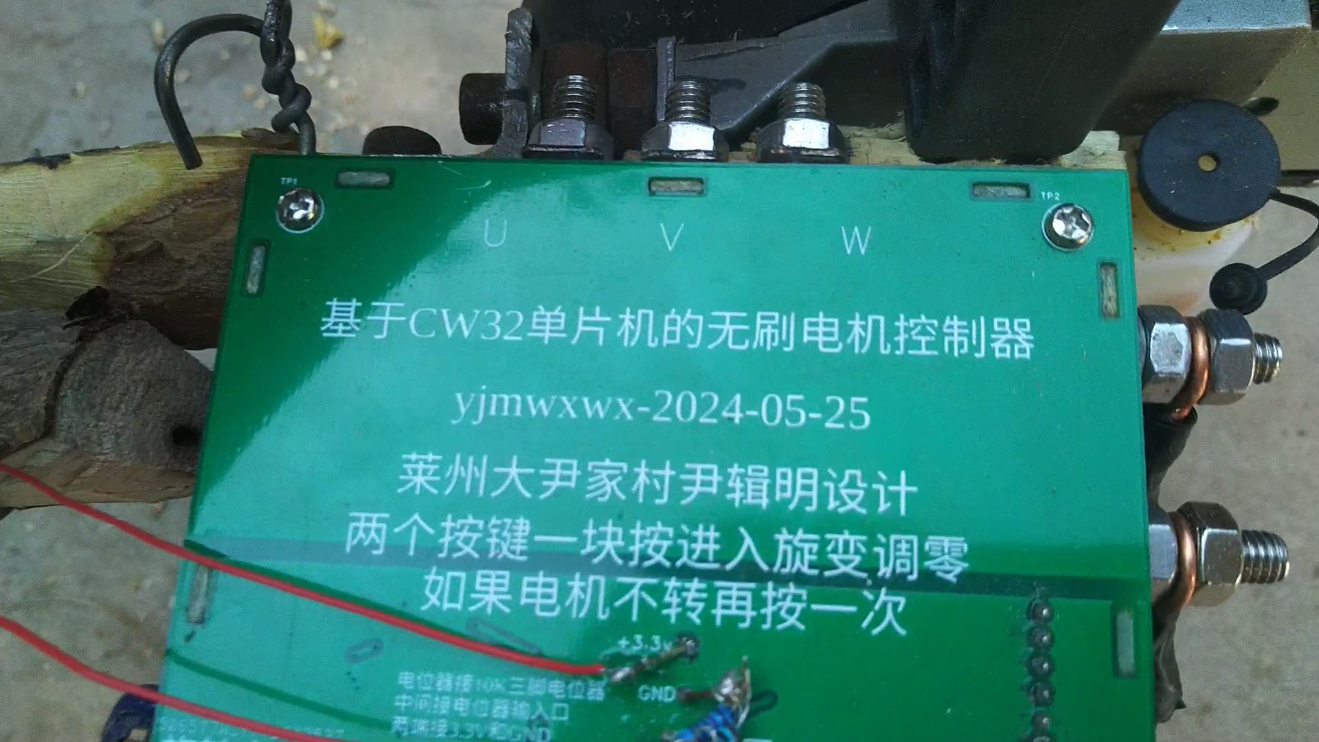
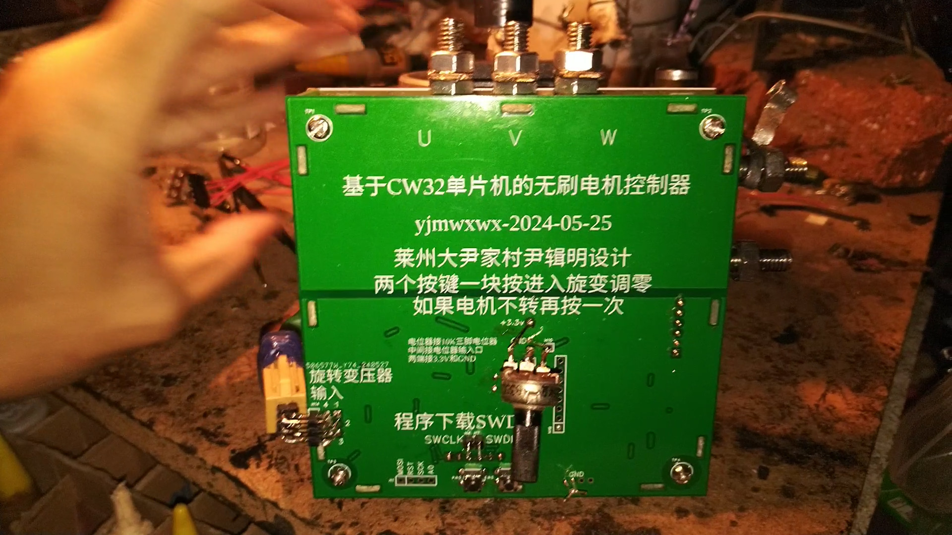
Brushless motor controller based on CW32 microcontroller (rotary transformer position feedback)
Simple power steering resolver brushless motor driver
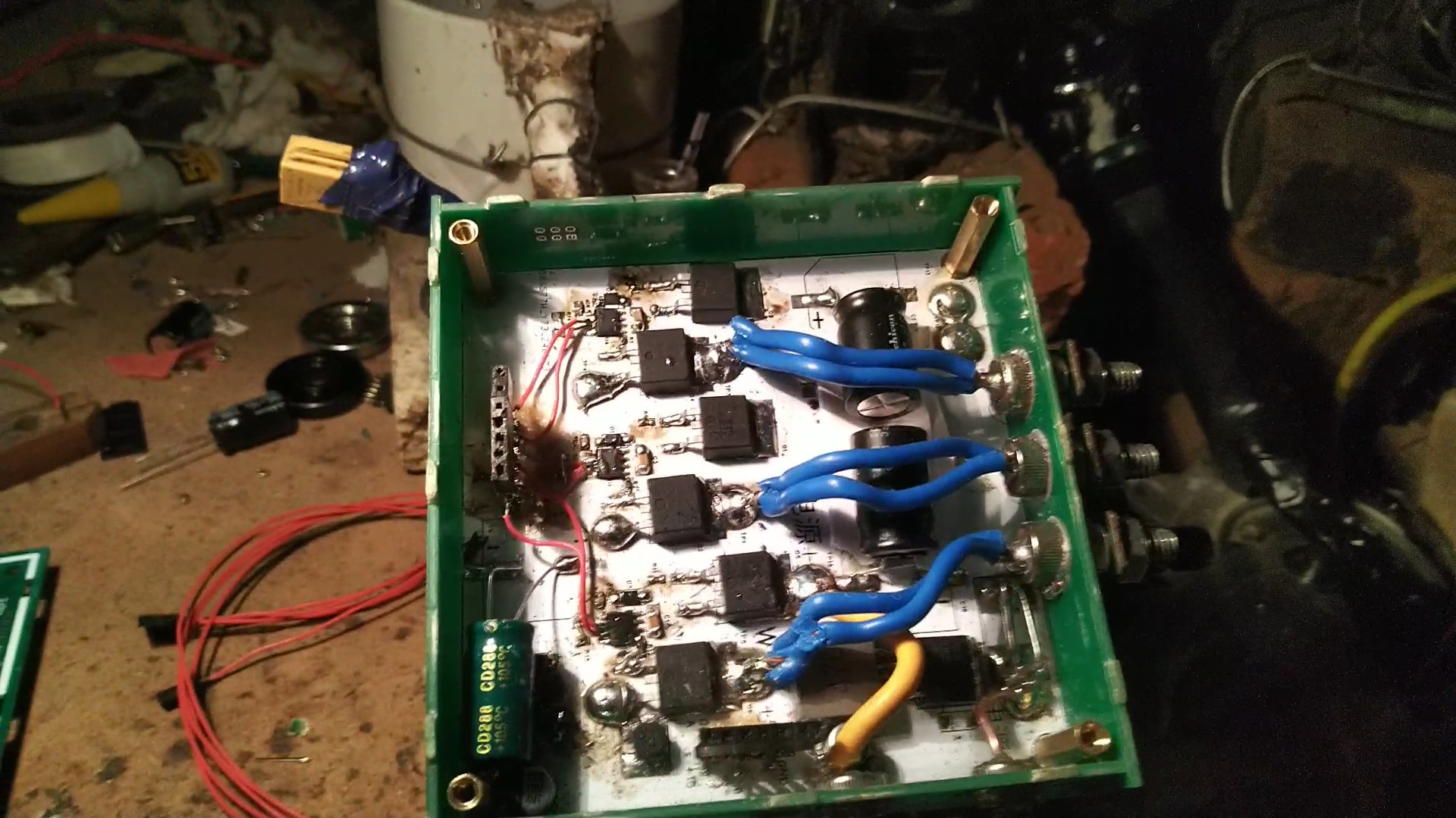
A simple brushless motor controller was built using a CW32 microcontroller. The power supply voltage is 12V to 14V. The motor is a power steering motor with a rotary transformer for position feedback. The control method uses the simplest open-loop current control, with SVPWM electrical angle advance of the rotor by 90 degrees, suitable for driving loads that do not require precise control. There is no current detection, only maximum current protection.
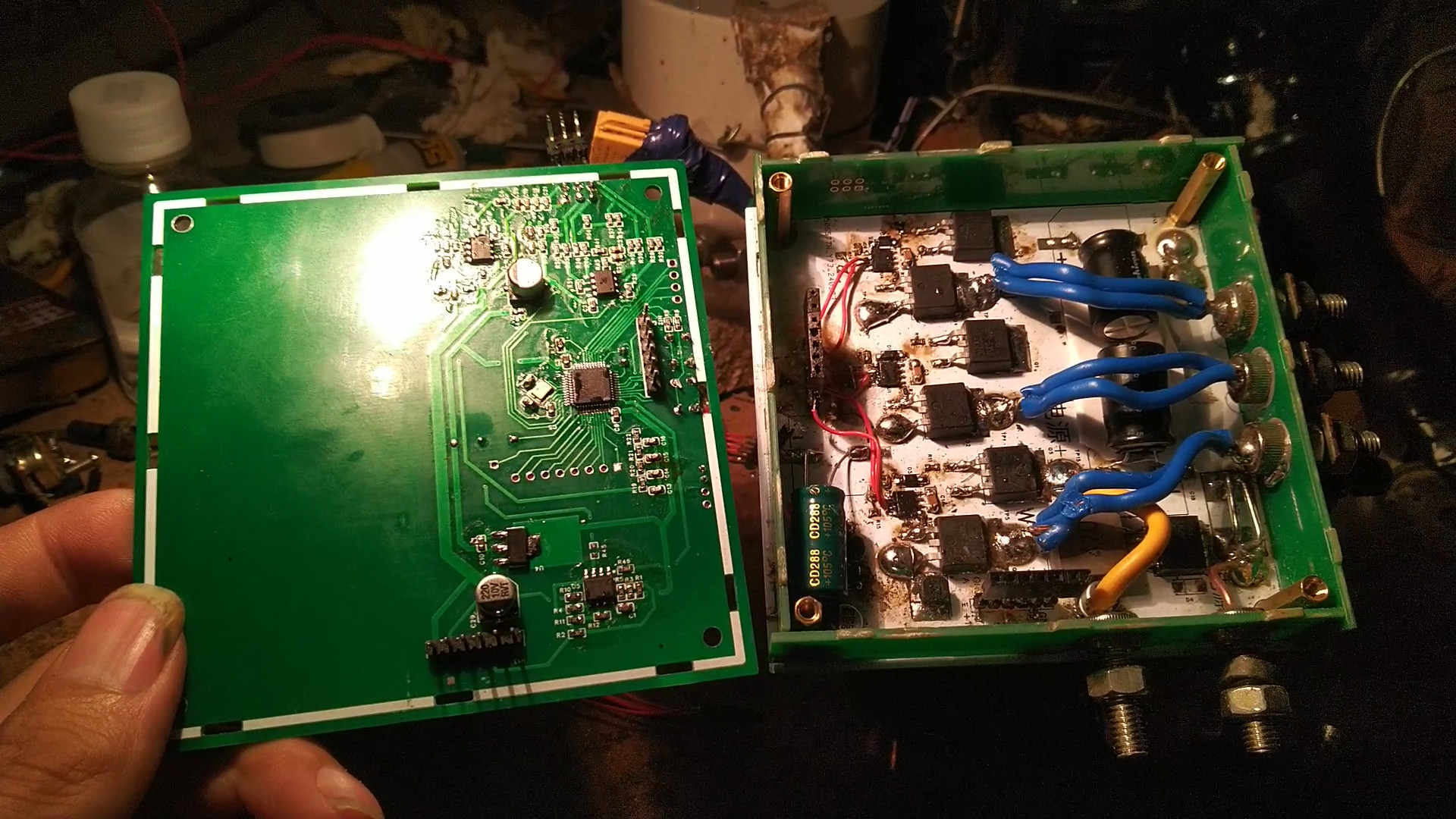
M6 screws are used for the terminals, directly soldered with 4 square copper wire between the two MOSFETs on the aluminum substrate. The power board is also on an aluminum substrate, connected to the circuit GND using M3 screws. The MOSFET's GND also needs to be connected to the aluminum board using M3 screws; the entire aluminum board serves as GND. For
the speed control potentiometer, a three-pin potentiometer less than 10K is preferred. The potentiometer input is connected to the ADC port in the middle, with the two ends connected to GND and the 3.3V
current limiting circuit. R45 is not soldered. A nut is soldered to the connector pins between the aluminum substrate and the control board, with the appropriate height. A
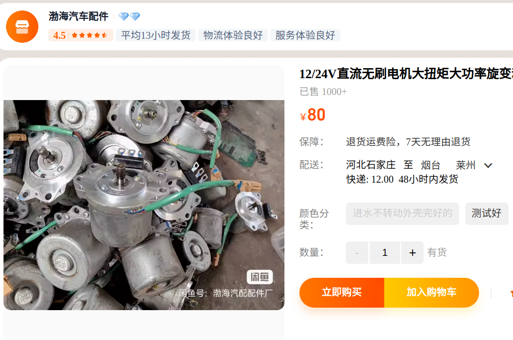
6-wire rotary transformer automotive power steering motor is needed. You can find cheaper options yourself; there are many such motors available, some costing around 60 yuan. However, remember it must be a 6-wire rotary transformer; ask about the exact price when purchasing. After soldering the board, two buttons need to be pressed simultaneously to zero the resolver. The potentiometer should be set slightly lower or the current limited. If zeroing is successful, the motor will rotate. If unsuccessful, press the buttons several times. The zeroing program is poorly written and often fails, but it only needs to succeed once, as the parameters will be saved to the FLASH memory.
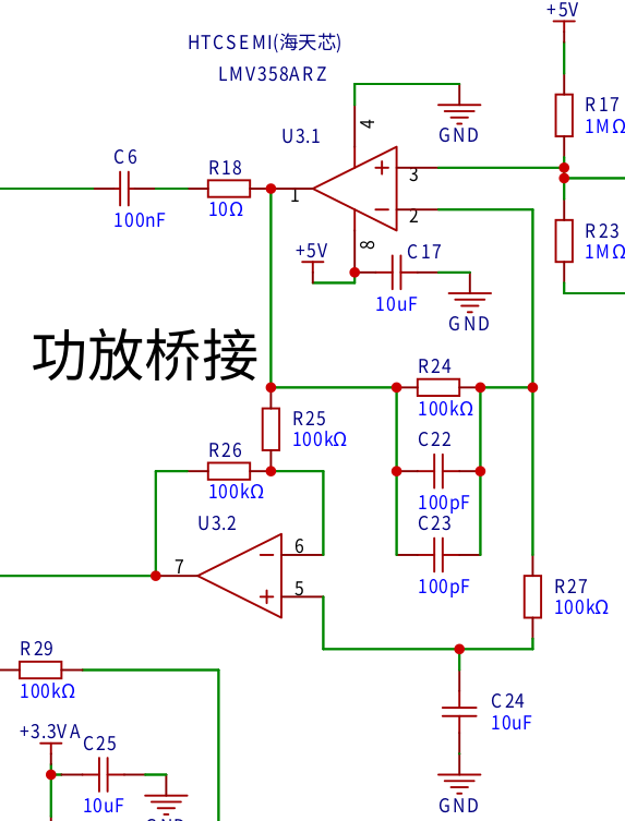
The resolver uses microcontroller software to calculate the angle. Dedicated decoding chips are expensive; for less demanding applications, a microcontroller can be used as a substitute. The external circuitry is relatively simple:
the microcontroller outputs a 20kHz SPWM, which is filtered by RC to become a sine wave. After passing through a 100NF capacitor, the voltage is boosted by half to 5V.

Then it enters U3.1 for amplification. C24 provides a DC reference point, C22 and C23 limit the bandwidth and attenuate the signal, R18 prevents high-frequency oscillation, and C6 isolates the circuitry before and after the signal to increase the stability of subsequent circuits. The U3.2 inverting output
rotary transformer is integrated into the motor. The reactance is measured using an LCR meter, and the reactance at 20kHz is calculated simultaneously. The inductor's reactance is positive, while the capacitor's is negative; therefore, capacitors with the same reactance (but opposite signs) are selected. Here, I used four 10NF capacitors in parallel to smooth the signal and filter interference. The motor casing must be connected to GND!

The COS and SIN from the rotary transformer are boosted to half of 3.3V and then enter two differential amplifiers. After amplification, they enter
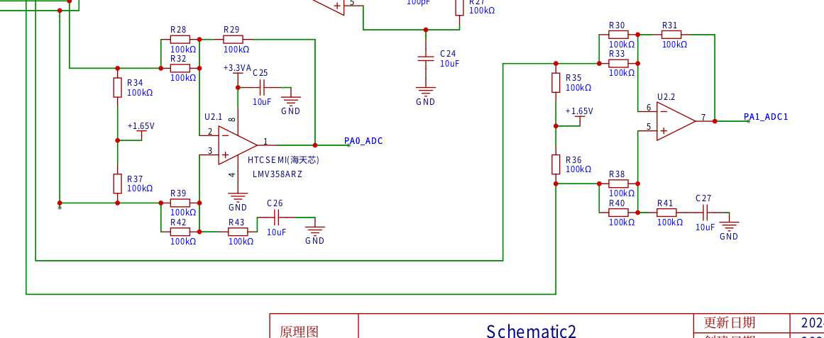
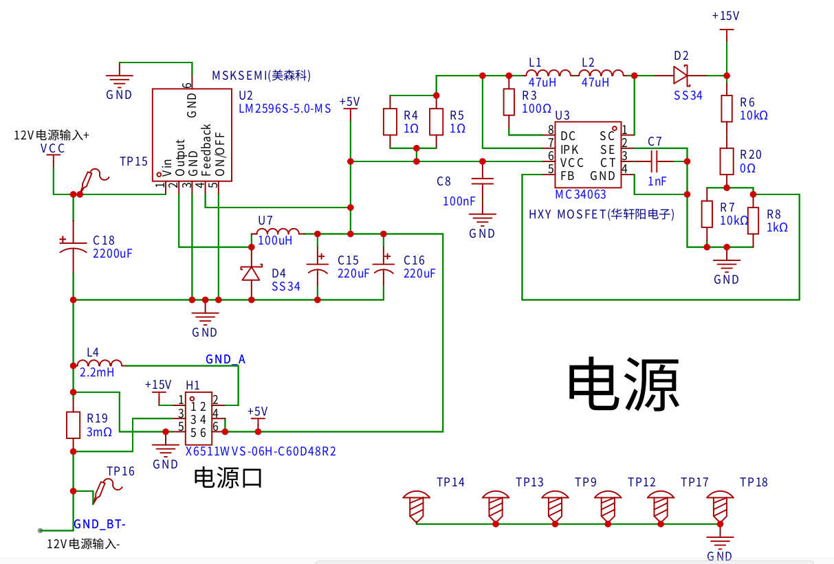
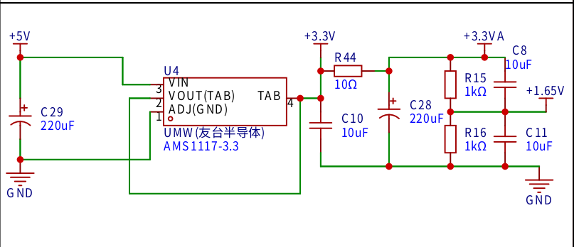
the power supply circuits for two ADC ports. The power supply needs a high current output capability, exceeding 100A. Therefore, a 12V 9A motorcycle starter battery is used. The voltage is stepped down to 5V by an LM2596 and boosted to 15V by an MC34063 to power the EG2131 MOSFET driver chip.
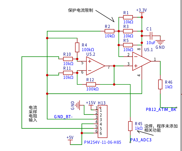
R19 is a current sampling resistor; in practice, two 3mΩ resistors are soldered in parallel. A single 3mΩ resistor will trigger protection if the motor is stalled, requiring a power switch to deactivate the protection.
The system uses a MOSFET H-bridge, with an EG2131 driver chip and an IRF2804

MOSFET. The microcontroller is a CW32F030C8T6, handling both resolver decoding and motor drive. Pressing two buttons together initiates the resolver zeroing procedure. The potentiometers for PA2 and ADC2 are slightly depressed. If zeroing is successful, the motor will rotate; otherwise, pressing both buttons again re-enters the zeroing procedure. Individual buttons control forward and reverse rotation, respectively. The system includes
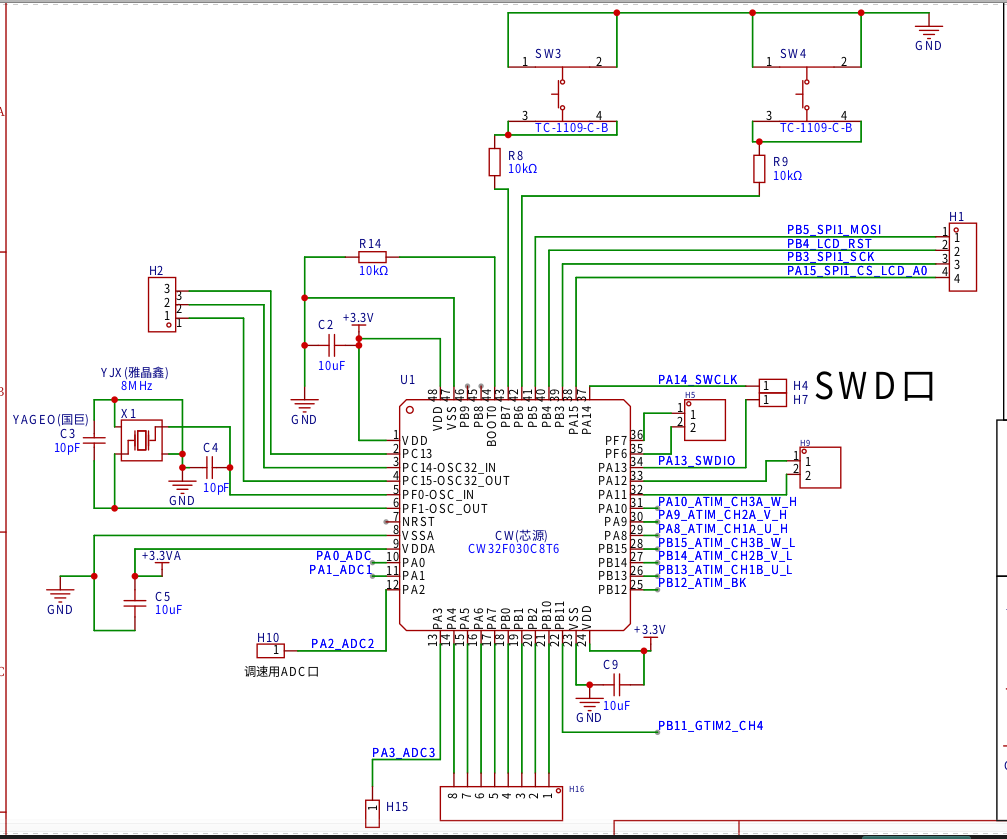
a current protection circuit ,
a 3.3V power supply circuit,
and a resolver soft decoding algorithm. Each microcontroller port corresponds to a 1MHz sampling rate. After acquiring 100 points, an interrupt is triggered. The DFT is used to calculate the real and imaginary parts of the acquired COS and SIN sequences. The phase is rotated to 0 degrees, and the real part is used to calculate the angle in ATAN2. The current angle is saved to a register. When the next angle is measured, the difference is subtracted to calculate the angle difference. The COS and SIN of the angle difference are then calculated and fed back to ATAN2. Rotating the angle into ATAN2 achieves phase locking, thus the obtained angle is independent of the rotation speed, offsetting system delay.
With a sampling rate of 10kHz and angle information updated 10,000 times per second, phase shift calculation is performed at 95,500 RPM. In fact, no calculation is needed; the result is simply the angle difference between two sampled data points.
= zhuansu = 95500shijian = 100xiangyi =90-atan2(159155 / (zhuansu / 60), shijian)*180/3.1415927
SVPWM algorithm (Note that this is my personal understanding and I cannot guarantee its correctness)
The H-bridge has a total of 8 switching states. 000 and 111 are empty vectors
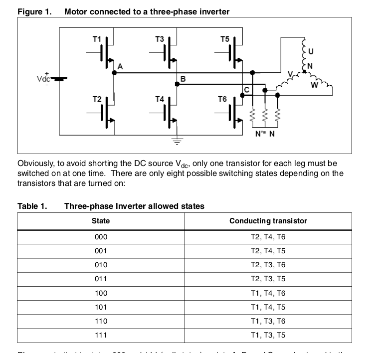
divided into 6 regions. Each 60-degree

drive H-bridge timer uses center alignment mode. 111 and 000 are empty vectors. Only one switching action is performed at the same time.

My driving frequency is 10KHZ. The timer ARR contains 2399. Below is my understanding of the calculation method of ta, tb, and t0 in the above figure.
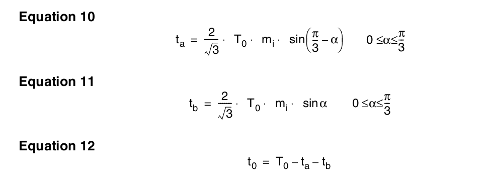
My understanding is the calculation method for 40 degrees. I don't know if it is correct.
ta = 1.154700538*1200*sind(60-40)
tb = 1.154700538*1200*sind(40)
t0 =
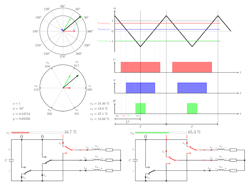
Example of 2399-ta-tb above, calculate the percentages of u1 and u3
: u1 = 1.154700538*0.86*2399*sind(60-40)/4799
u3 = 1.154700538*0.86*2399*sind(40)/4799
The actual calculation method of timer compare register data
is to generate a 0-60 degree lookup table, 2000 points, Q15 fixed point number
#include
#include
#include
void main() {
double x,p,y,i;
int jiaodu,rr,ii,n;
n = 60;
for(i=0;i
{
p = i*3.1415926536897932384626/180;
x = (sin(p)* cos(0))/ (sin(1.0471975) * cos(0));
y = (cos(p) - (x * cos(1.0471975))) / cos(0);
rr = x*0x8000;
ii = y*0x8000;
//printf ("%f,%f
",x,y);
printf("0x%04X,0x%04X,", rr,ii);
}
printf("
");
Retrieve X and Y values for 0-60 degrees from a lookup table:
x*2399= u1
y*2399= u3
2399-u1-u3 = zero vector
In the actual program, I modified 2399 to 2048 for calculation. This ensures the PWM duty cycle doesn't exceed the maximum. From
0 to 60 degrees, the timer compare register values are calculated:
W phase calculation: zero vector divided by 2;
U phase calculation: (U1 vector) plus (U3 vector) plus (zero vector divided by 2);
V phase calculation: (U3 vector) plus (zero vector divided by 2);
60 to 120 degrees : W phase calculation: (zero vector
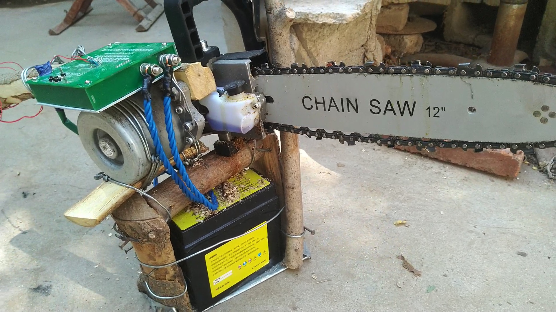
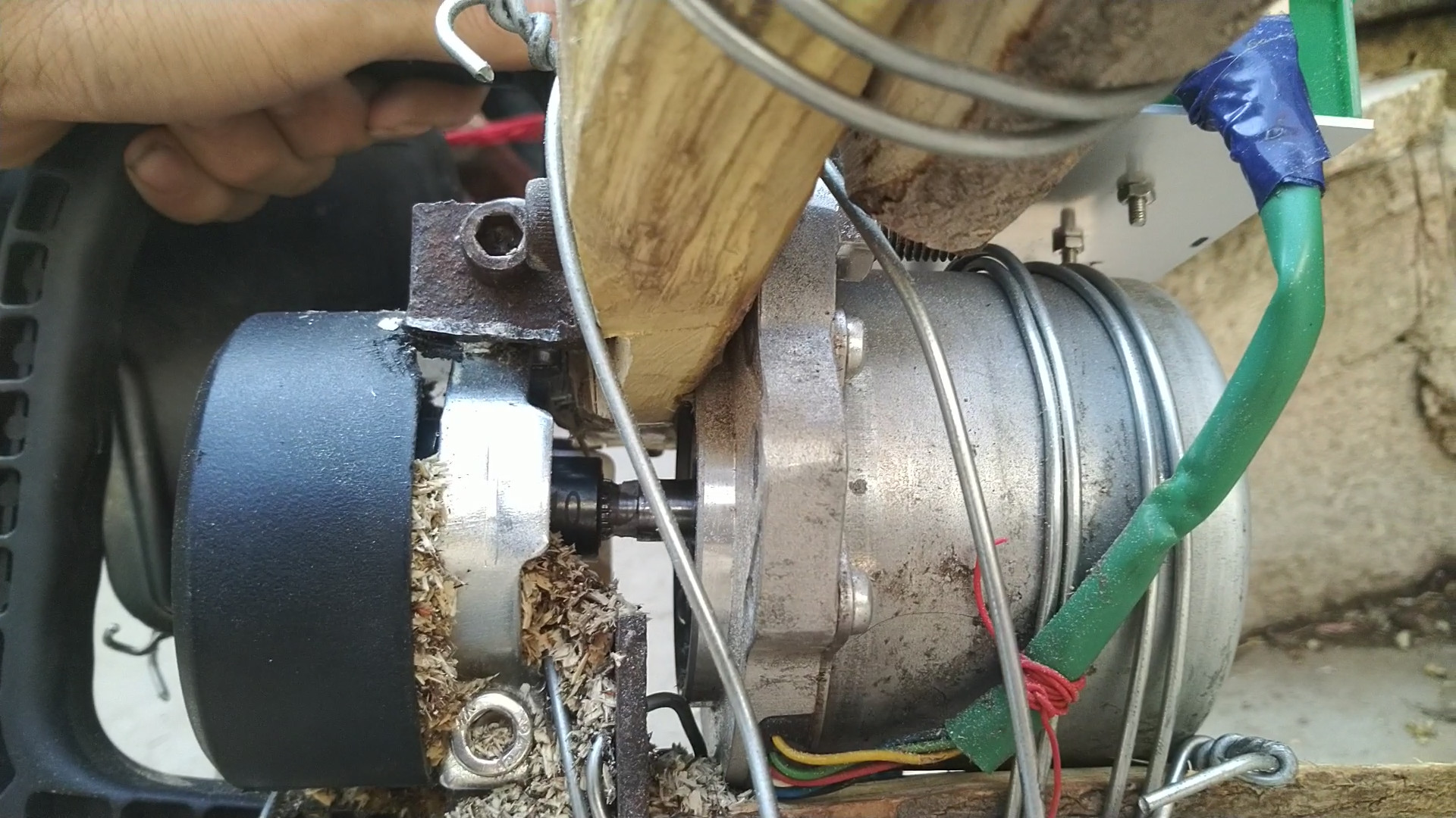
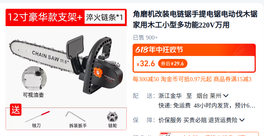
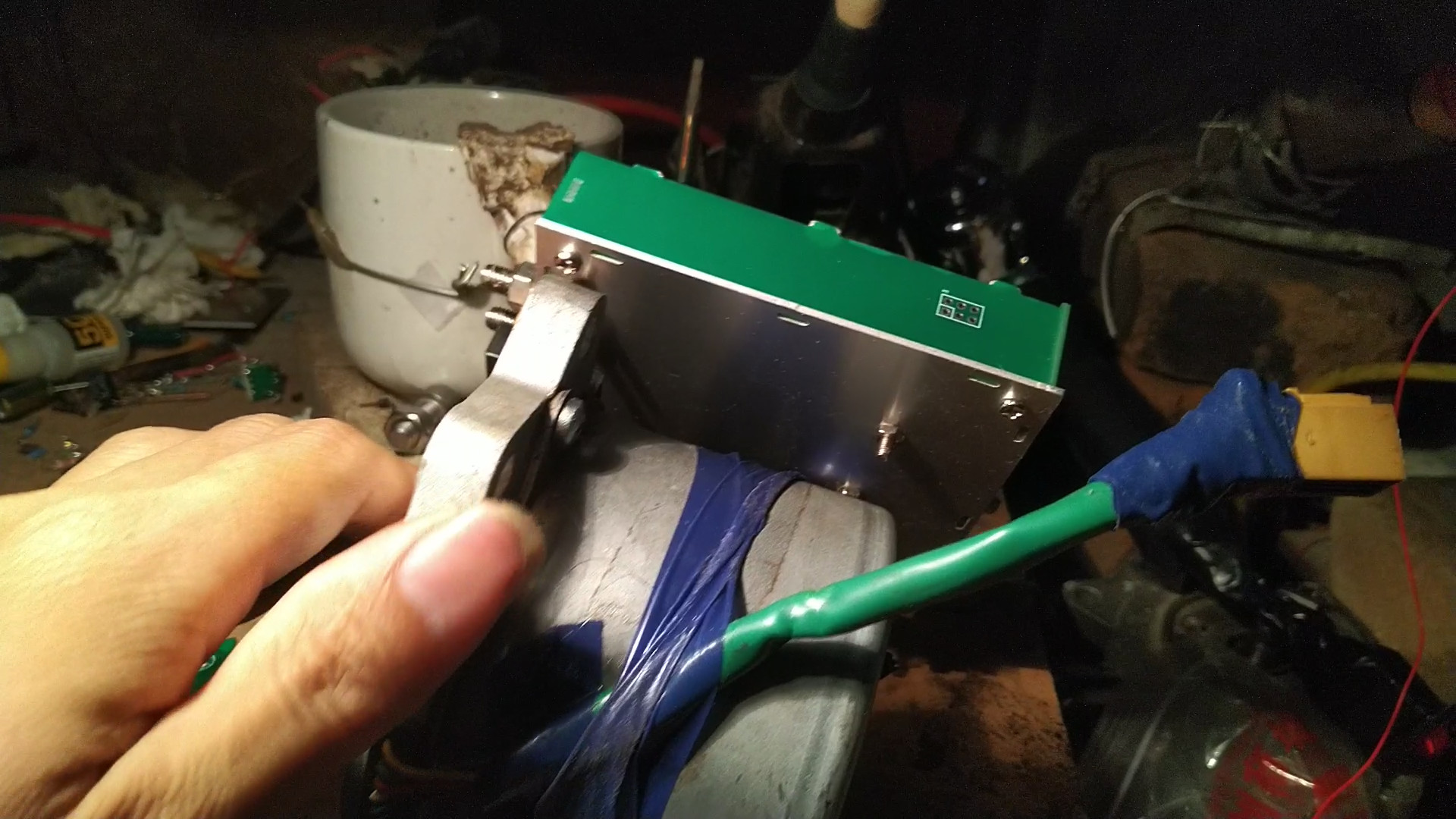
divided by 2) ; U phase calculation: (U1 vector) plus (zero vector divided by 2) ; V phase calculation: (timer maximum count 2399) minus (zero vector divided by 2). The remaining angles are directly obtained by swapping the UVW registers. Refer to the partition diagram for different switch combinations. The SVPWM electrical angle is 90 degrees ahead of the rotor measured by the rotary transformer. This way, speed adjustment only requires controlling the modulation ratio. Precise control of position and speed requires controlling the modulation ratio. The electric chainsaw used to modify the motor for the copper pillars in the controller assembly is used to verify whether the controller can be connected to the motor bushing using a modified electric chainsaw kit . A 10mm screwdriver is needed; the motor shaft is 10.8mm, so a 10.5mm drill bit can be used to enlarge the hole. [Controller actual product image]


1.mp4
program.zip
My attempt to make a chainsaw with a brushless motor failed. (mp4)
Program source code and firmware (modulation ratio fixed 20240605).zip
SVPWM Algorithm Data.zip
svpwm.mp4
The effect after modifying the program (dry wood is harder to cut than last time 20240605).mp4
image-asset.gif
Program source code and firmware (final version, modulation ratio fixed 20240607).zip
Successfully modified electric chainsaw.mp4
Source code and firmware 20240705 (with added resolver angle compensation).zip
PDF_CW32 Microcontroller-Based Brushless Motor Controller (Resolver Position Feedback).zip
Altium_CW32 Microcontroller-based Brushless Motor Controller (Resolver Position Feedback).zip
PADS_CW32 Microcontroller-Based Brushless Motor Controller (Resolver Position Feedback).zip
BOM_CW32 Microcontroller-Based Brushless Motor Controller (Resolver Position Feedback).xlsx
91237
Homemade Succubus Glasses
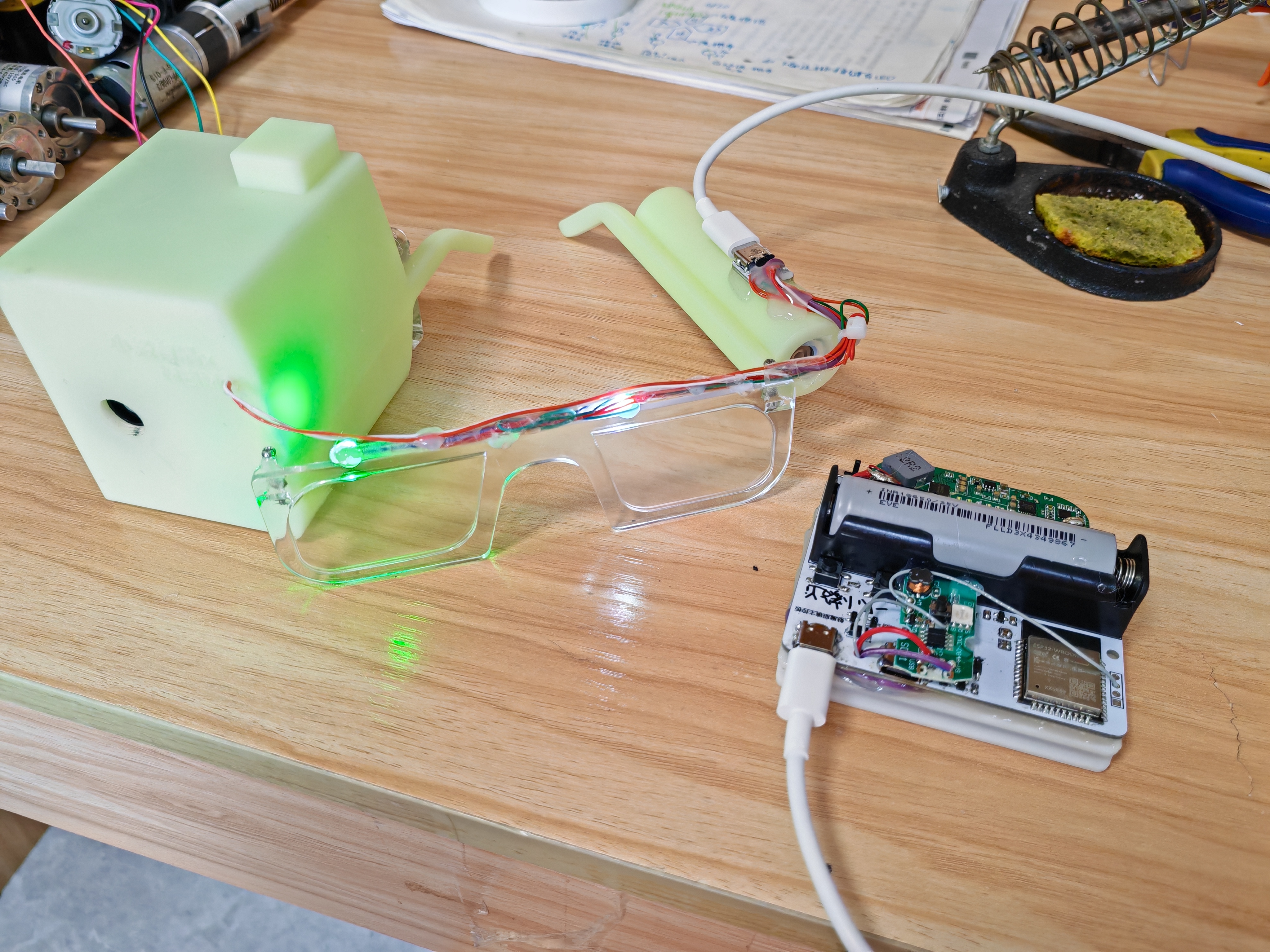
A magical pair of prop glasses with functions including RGB lights on the lenses for displaying changing lighting effects, a bubble machine on the left frame for blowing colorful bubbles, and a humidifier module on the right frame for creating a smoky atmosphere. It's perfect for pranks and creating a lively atmosphere at parties.
I. Design Functions:
A magical pair of glasses with features including RGB lights on the lenses for displaying changing lighting effects, a bubble machine on the left frame for blowing colored bubbles, and a humidifier module on the right frame for creating a smoky atmosphere. Suitable for pranks and creating a lively atmosphere at parties. All functions can be controlled via a mobile app or a button. II. Structure:
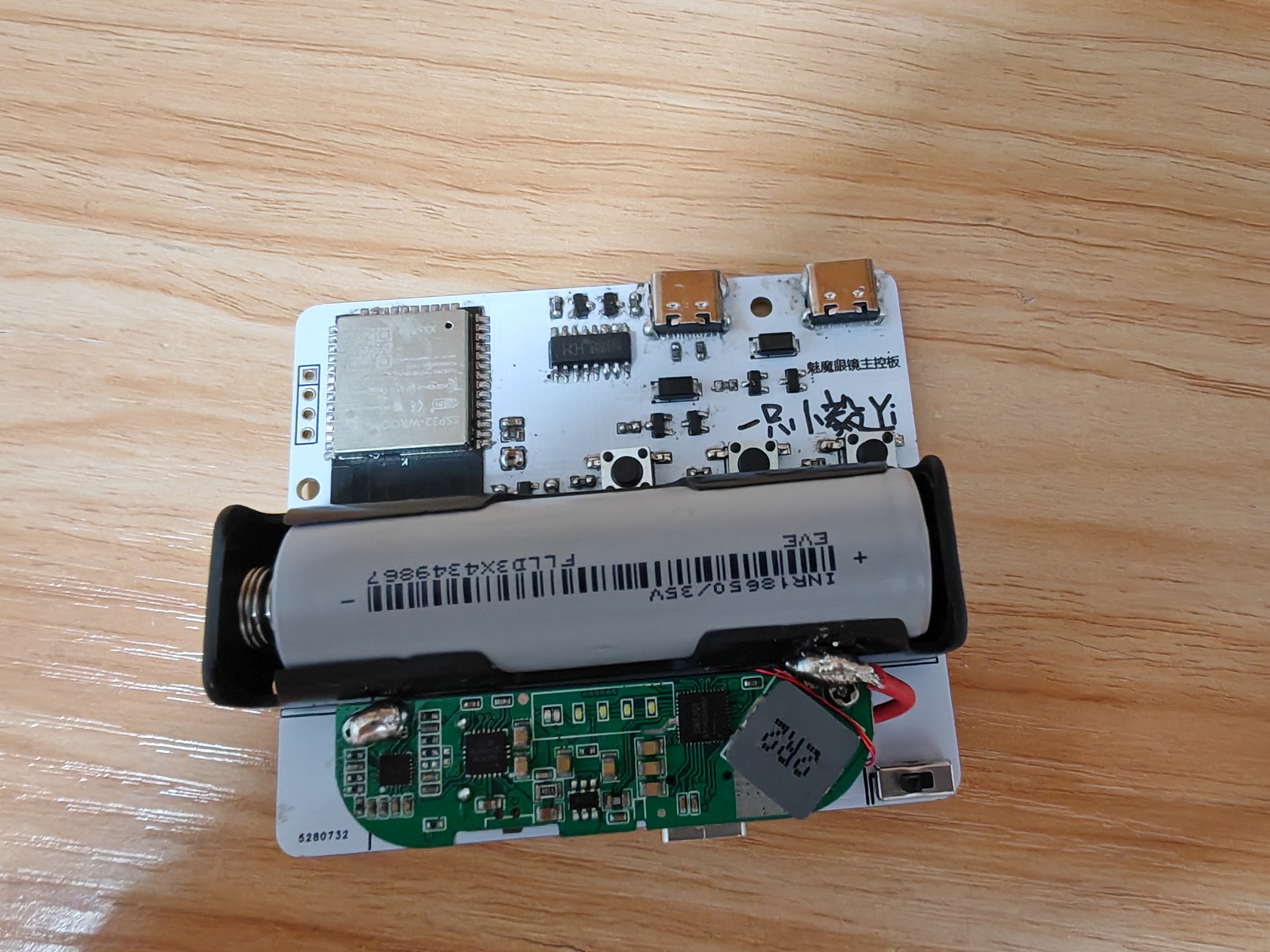
The glasses themselves, along with a motherboard and battery box hanging on the back of the neck, are connected via a double-ended Type-C cable (proprietary protocol).
The glasses integrate two RGB lights, an ultrasonic atomizing plate with corresponding cotton swabs, a bubble machine, and a corresponding bubble solution bottle. An adapter board inside the glasses converts the cables of these devices to Type-C for easy connection to the main control box
. The box contains the circuitry and battery; the left Type-C port is used for uploading programs, the right Type-C port connects to the glasses, and the bottom Type-C port is used for charging (supports reverse charging as a power bank).
Materials used:
Bubble machine (core removed from disassembly). https://detail.tmall.com/item.htm?id=701462940556&spm= a1z09.12.0.0.11ca2e8dny0jW0&_u=j20c6g5s2te348
Humidifier (Core removed after disassembly) https://detail.tmall.com/item.htm?id=733374679653&spm=a1z09.12.0.0.11ca2e8dny0jW0&_u=j20c6g5s2t1d04
Power Bank Motherboard https://item.taobao.com/item.htm?spm=a1z09.12.0.0.11ca2e8dny0jW0&id=701513981873&_u=j20c6g5s2t54e6
(The resistor on the back needs to be changed to 10k.)
See the attached 3D printing file. Below is the assembly diagram: the bubble machine is installed on the left temple, and the spray module is installed on the right temple (left and right directions shown in the diagram). The humidifier is filled to hold the spray cotton strips.

III. Circuit details
are in the editor below. The actual circuit board diagram is shown below.
IV. Code:
See the attached ESP32 code (all.ino).
You need to download "Bluetooth Serial Port SPP" (attached base.apk) on your phone first, and then follow the instructions in the attached video.
V. Finished Product
3D Printing Files.zip
APP Setup Tutorial.mp4
All.ino
base.apk
Demo video (2).mp4
PDF_DIY Succubus Glasses.zip
Altium_DIY Succubus Glasses.zip
PADS_DIY Succubus Glasses.zip
91238
ECHO Heated Stand (V2)
The ECHO heating stage V2 version combines domestically produced STC microcontrollers with domestically produced EDA design software, a powerful collaboration!
Update Log
2024/06/28
Released ECHO Heating Platform V2
Precautions
: After setting up the ECHO heating platform:
Activate and set
the power. Clean
the heating plate
. Heat at approximately 220℃ for 1 minute to oxidize the aluminum substrate surface.
After completing the above steps, the heating plate will have very little solder adhesion.
Optimal operating temperature: 100-240℃, short-term operation at 300℃ is fine. Due to the insulation material of the aluminum substrate, excessively high temperatures will produce harmful gases and cause irreversible damage! Open Source
License
This project uses the CC-BY-NC-SA 3.0 open source license, i.e., Creative Commons Attribution-NonCommercial-ShareAlike.
CC: Creative Commons License
BY: Attribution, you must give appropriate attribution, provide a link to this license, and indicate whether modifications were made (to the original work).
SA: ShareAlike, if you remix, transform, or build upon this work, you must share your contributions under the same license as the original.
NC: NonCommercial, you may not use this work for commercial purposes. The ECHO heating platform V2 uses an STC8H8K64U microcontroller with built
-
in USB functionality, powered by a CH224K decoy chip, and supports PD3.0/2.0 protocols. The screen is a 0.96-inch TFT LCD display with a 45° angled display. The heating plate is made of aluminum (in three versions: H34/H50/H100), and the outer shell is 3D printed (PLA or FDM). The controller and heating plate are pluggable, facilitating the use of different heating platform models.
The domestically produced STC8H8K64U chip
features built-in USB hardware, supporting software updates
. The Type-C power interface supports PD3.0/2.0 protocols.
A 0.96-inch TFT color LCD screen
with a 45° angled display makes data viewing more convenient
. A front-mounted dial switch facilitates one-handed operation.
Three operating modes are available: constant temperature mode, curve mode, and reflux mode.
The controller and heating platform have a plug-in design, supporting the replacement of heating plates of different areas. The outer
shell can be printed using photopolymer 3D printing. Different colors and materials can be selected
using JLCPCB 3D printing.
The ECHO control board is designed as a double-layer board, allowing users to utilize JLCPCB's newly upgraded immersion gold process.
Operation instructions:
The buttons have three positions: upper, middle, and lower.
The upper and lower buttons default to an increase/decrease principle.
The middle button is the function button.
1) On the main interface, click the function button to control heating on/off. When the main interface is in constant temperature mode, double-clicking the function button switches the display between power and internal resistance.
2) On the main interface, long-press the function button to enter the settings menu.
3) In the settings menu, you can select five settings items: PID settings, parameter settings, mode settings, power settings, and basic settings by clicking the up and down buttons.
4) In the settings menu, click the function button to enter the corresponding first-level menu.
5) In the first-level menu, click the function button, select the item to be adjusted, and adjust the corresponding data using the up/down buttons. Long press the function button to return to the first-level menu.
6) In the first-level menu, long press the function button to return to the settings menu, and long press the function button again to return to the main interface.
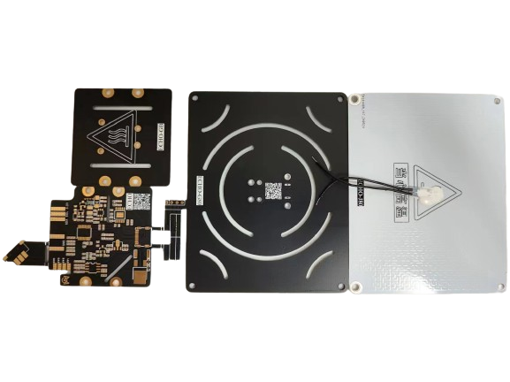
The
ECHO34 requires printing four PCB files: ECHO-Control Board, ECHO-Cover, ECHO-J34, and ECHO-G34.

Figure 1. PCBs required for ECHO34. The
ECHO50 requires printing four PCB files: ECHO-Control Board, ECHO-Cover, ECHO-J50, and ECHO-G50.
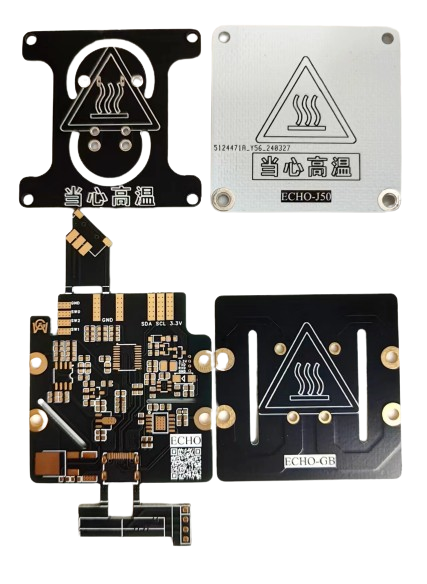
Figure 2. PCBs required for ECHO50 .
The PCBs required for ECHO100 (not yet open source).
ECHO-J34 and ECHO-G34 are combined to form the H34 heater.
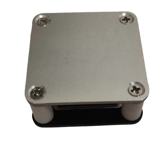
Figure 3. The H34 heater
ECHO-J50 and ECHO-G50 are combined to form the H50 heater.

Figure 4. The H50 heater
ECHO-control board and ECHO-cover plate are combined to form the controller.
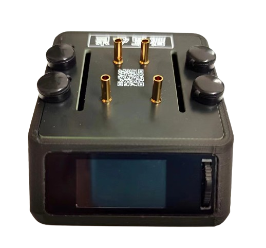
Figure 5. The controller
can be combined with the H34 heater/H50 heater/H100 heater to form ECHO34/ECHO50/ECHO100 respectively.
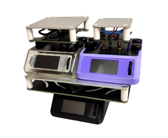

Figure 6. ECHO Whole Box
Soldering and Assembly Tutorial
I. Soldering
Tutorial Refer to the first-generation soldering tutorial for the soldering tutorial.
ECHO - Control Board Soldering: [Part 1] [Control Board Soldering]
ECHO - Controller Assembly: [Part 2] [Controller Assembly]
ECHO - Heating Plate and Temperature Sensor Assembly: [Part 3] [Heating Plate and Temperature Sensor Assembly]
ECHO - Heater Assembly [Part 1]: [Part 4 (Part 1)] [Heater Assembly]
ECHO - Heater Assembly [Part 2]: [Part 4 (Part 2)] [Heater Assembly]
ECHO Heating Table V2 Version Explanation Video: ECHO Heating Table V2 Version Explanation Video
Soldering Precautions
Online soldering auxiliary tools are in the attachment:


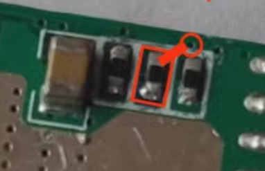
The above picture is a physical soldering diagram. There are three points to note:
Do not solder the C75K capacitor
. Do not solder R32
. Solder R37 and R38 as shown in the diagram.
Solder the 8P base of the screen to the corresponding 8P screen. 13P is for soldering the screen.
II. Program Download Tutorial
Ensure correct soldering before proceeding!
Open the STC-ISP software on your computer, plug in the Type-C data cable,
press and hold the ECHO heating station function button, and quickly insert the Type-C data cable's C port into the ECHO heating station's C port
. If the soldering is completely correct, the STC-ISP software will display "STC-USB Writer (HID1)," as shown in Figure 7.
If the hardware is not correctly identified, repeat steps b and c until it is correctly identified

(Figure 7).
After successful hardware identification, perform the following operations (Figure 8):
Chip model selection: STC8H8K64U;
IRC frequency: 24MHz
; EEPROM size: 0.5K;
Ope


 京公网安备 11010802033920号

 FP2001683002JBBCW


