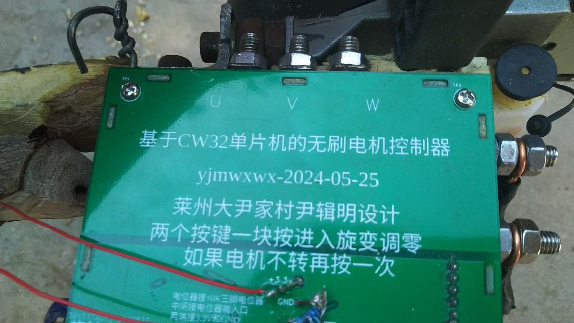
A simple brushless motor controller was built using a CW32 microcontroller. The power supply voltage is 12V to 14V. The motor is a power steering motor with a rotary transformer for position feedback. The control method uses the simplest open-loop current control, with SVPWM electrical angle advance of the rotor by 90 degrees, suitable for driving loads that do not require precise control. There is no current detection, only maximum current protection.
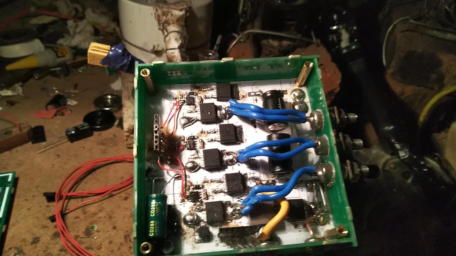
M6 screws are used for the terminals, directly soldered with 4 square copper wire between the two MOSFETs on the aluminum substrate. The power board is also on an aluminum substrate, connected to the circuit GND using M3 screws. The MOSFET's GND also needs to be connected to the aluminum board using M3 screws; the entire aluminum board serves as GND. For
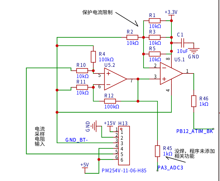
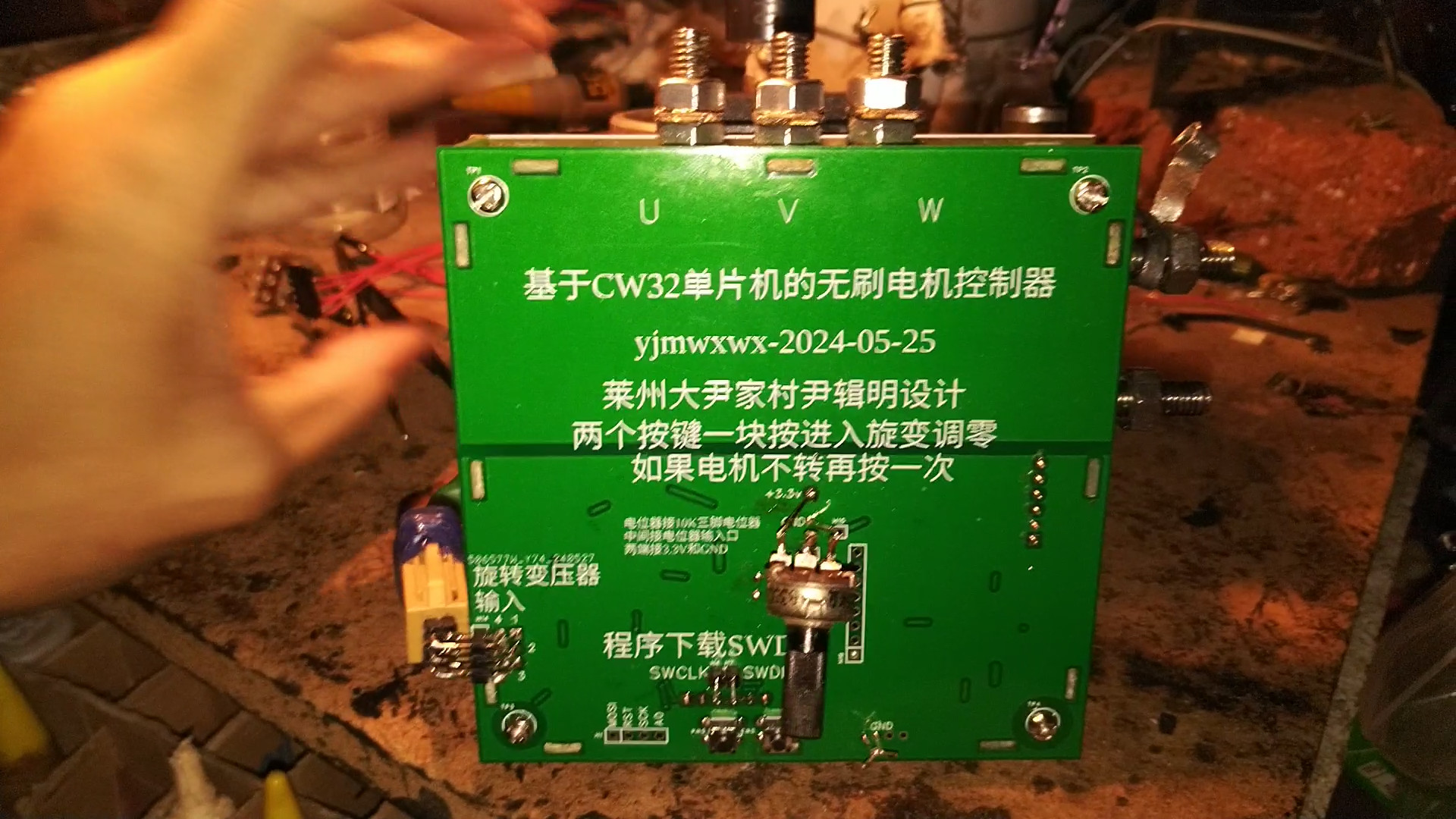
the speed control potentiometer, a three-pin potentiometer less than 10K is preferred. The potentiometer input is connected to the ADC port in the middle, with the two ends connected to GND and the 3.3V
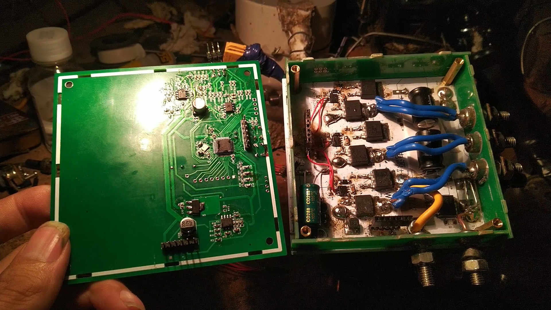
current limiting circuit. R45 is not soldered. A nut is soldered to the connector pins between the aluminum substrate and the control board, with the appropriate height. A
6-wire rotary transformer automotive power steering motor is needed. You can find cheaper options yourself; there are many such motors available, some costing around 60 yuan. However, remember it must be a 6-wire rotary transformer; ask about the exact price when purchasing. After soldering the board, two buttons need to be pressed simultaneously to zero the resolver. The potentiometer should be set slightly lower or the current limited. If zeroing is successful, the motor will rotate. If unsuccessful, press the buttons several times. The zeroing program is poorly written and often fails, but it only needs to succeed once, as the parameters will be saved to the FLASH memory.
The resolver uses microcontroller software to calculate the angle. Dedicated decoding chips are expensive; for less demanding applications, a microcontroller can be used as a substitute. The external circuitry is relatively simple:
the microcontroller outputs a 20kHz SPWM, which is filtered by RC to become a sine wave. After passing through a 100NF capacitor, the voltage is boosted by half to 5V.

Then it enters U3.1 for amplification. C24 provides a DC reference point, C22 and C23 limit the bandwidth and attenuate the signal, R18 prevents high-frequency oscillation, and C6 isolates the circuitry before and after the signal to increase the stability of subsequent circuits. The U3.2 inverting output
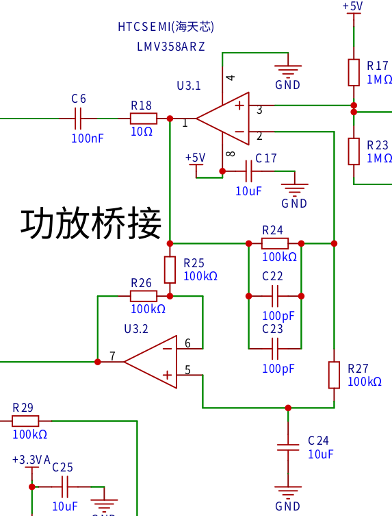
rotary transformer is integrated into the motor. The reactance is measured using an LCR meter, and the reactance at 20kHz is calculated simultaneously. The inductor's reactance is positive, while the capacitor's is negative; therefore, capacitors with the same reactance (but opposite signs) are selected. Here, I used four 10NF capacitors in parallel to smooth the signal and filter interference. The motor casing must be connected to GND!

The COS and SIN from the rotary transformer are boosted to half of 3.3V and then enter two differential amplifiers. After amplification, they enter
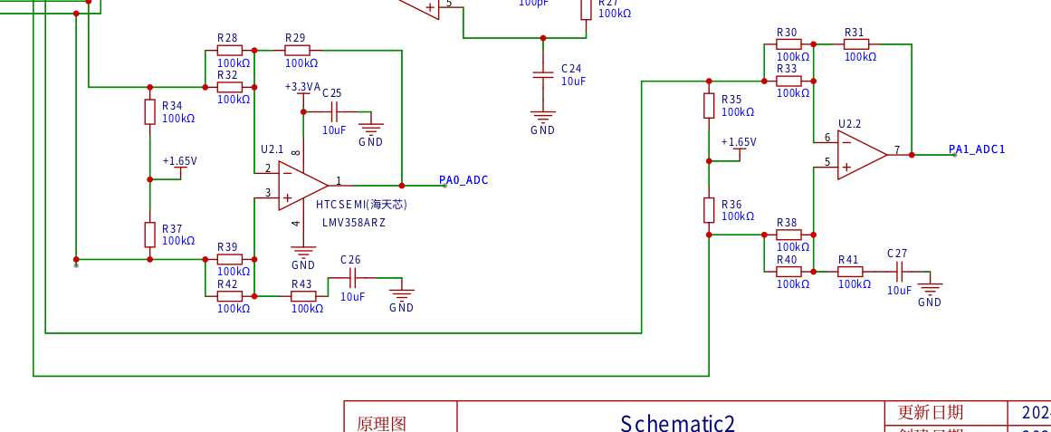
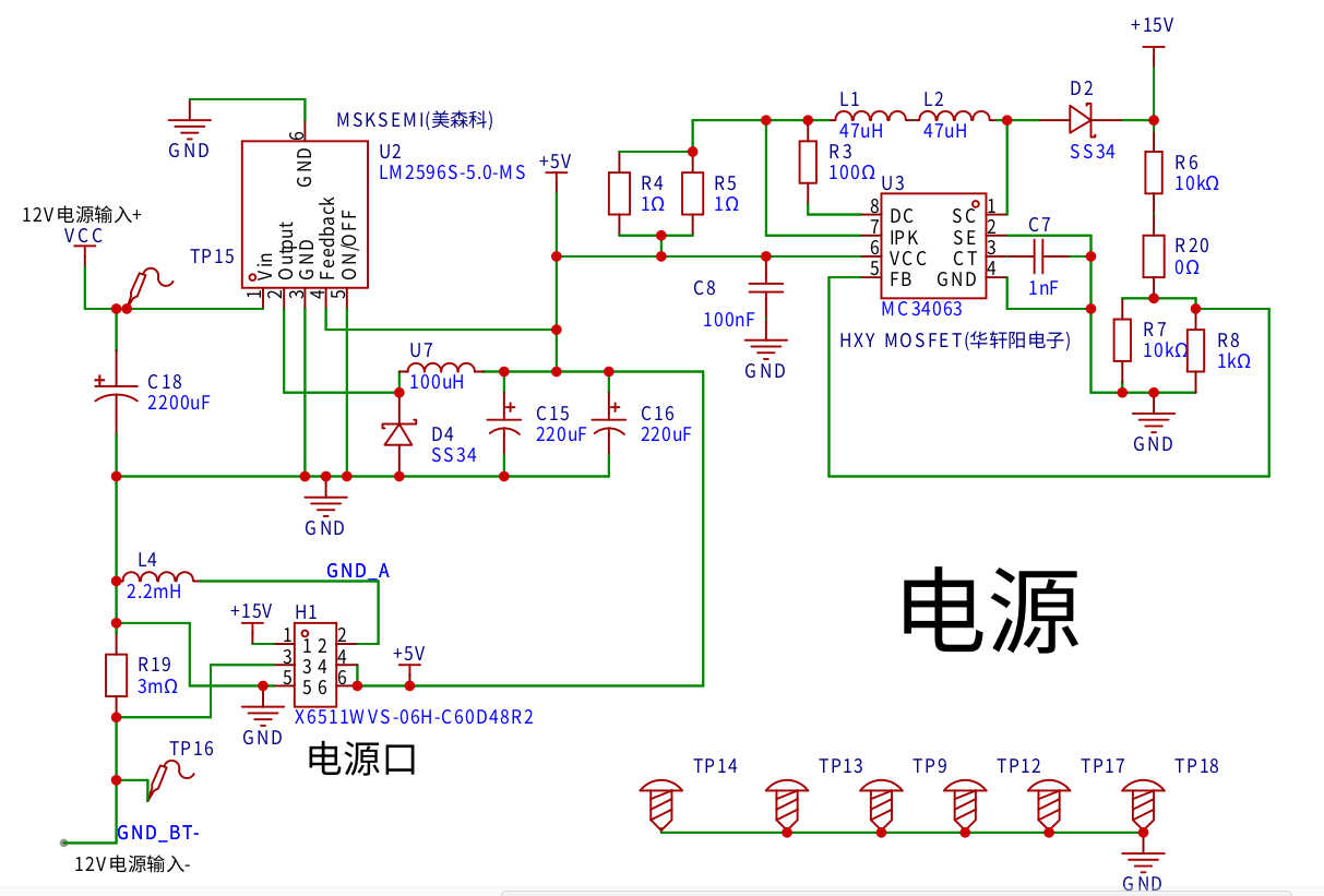
the power supply circuits for two ADC ports. The power supply needs a high current output capability, exceeding 100A. Therefore, a 12V 9A motorcycle starter battery is used. The voltage is stepped down to 5V by an LM2596 and boosted to 15V by an MC34063 to power the EG2131 MOSFET driver chip.
R19 is a current sampling resistor; in practice, two 3mΩ resistors are soldered in parallel. A single 3mΩ resistor will trigger protection if the motor is stalled, requiring a power switch to deactivate the protection.
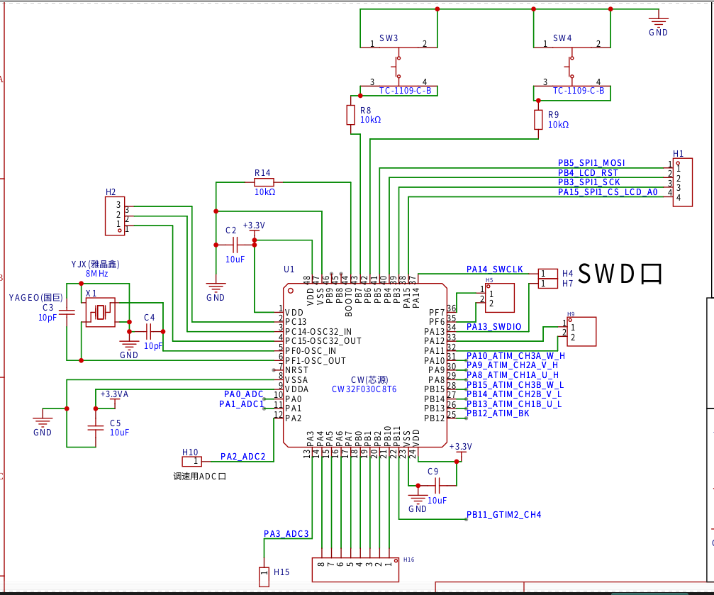
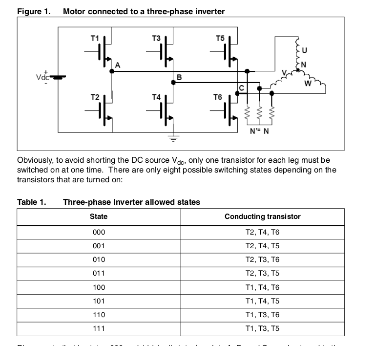
The system uses a MOSFET H-bridge, with an EG2131 driver chip and an IRF2804

MOSFET. The microcontroller is a CW32F030C8T6, handling both resolver decoding and motor drive. Pressing two buttons together initiates the resolver zeroing procedure. The potentiometers for PA2 and ADC2 are slightly depressed. If zeroing is successful, the motor will rotate; otherwise, pressing both buttons again re-enters the zeroing procedure. Individual buttons control forward and reverse rotation, respectively. The system includes
a current protection circuit ,
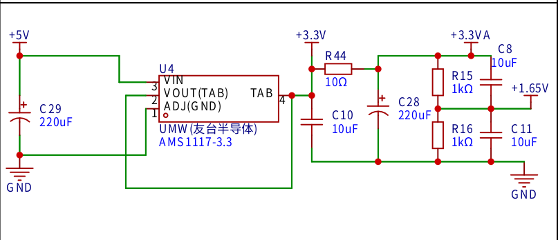
a 3.3V power supply circuit,
and a resolver soft decoding algorithm. Each microcontroller port corresponds to a 1MHz sampling rate. After acquiring 100 points, an interrupt is triggered. The DFT is used to calculate the real and imaginary parts of the acquired COS and SIN sequences. The phase is rotated to 0 degrees, and the real part is used to calculate the angle in ATAN2. The current angle is saved to a register. When the next angle is measured, the difference is subtracted to calculate the angle difference. The COS and SIN of the angle difference are then calculated and fed back to ATAN2. Rotating the angle into ATAN2 achieves phase locking, thus the obtained angle is independent of the rotation speed, offsetting system delay.
With a sampling rate of 10kHz and angle information updated 10,000 times per second, phase shift calculation is performed at 95,500 RPM. In fact, no calculation is needed; the result is simply the angle difference between two sampled data points.
= zhuansu = 95500shijian = 100xiangyi =90-atan2(159155 / (zhuansu / 60), shijian)*180/3.1415927
SVPWM algorithm (Note that this is my personal understanding and I cannot guarantee its correctness)
The H-bridge has a total of 8 switching states. 000 and 111 are empty vectors
divided into 6 regions. Each 60-degree

drive H-bridge timer uses center alignment mode. 111 and 000 are empty vectors. Only one switching action is performed at the same time.

My driving frequency is 10KHZ. The timer ARR contains 2399. Below is my understanding of the calculation method of ta, tb, and t0 in the above figure.
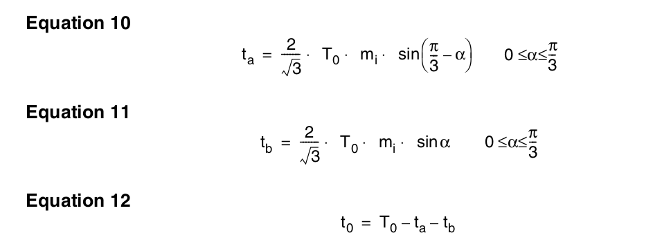
My understanding is the calculation method for 40 degrees. I don't know if it is correct.
ta = 1.154700538*1200*sind(60-40)
tb = 1.154700538*1200*sind(40)
t0 =
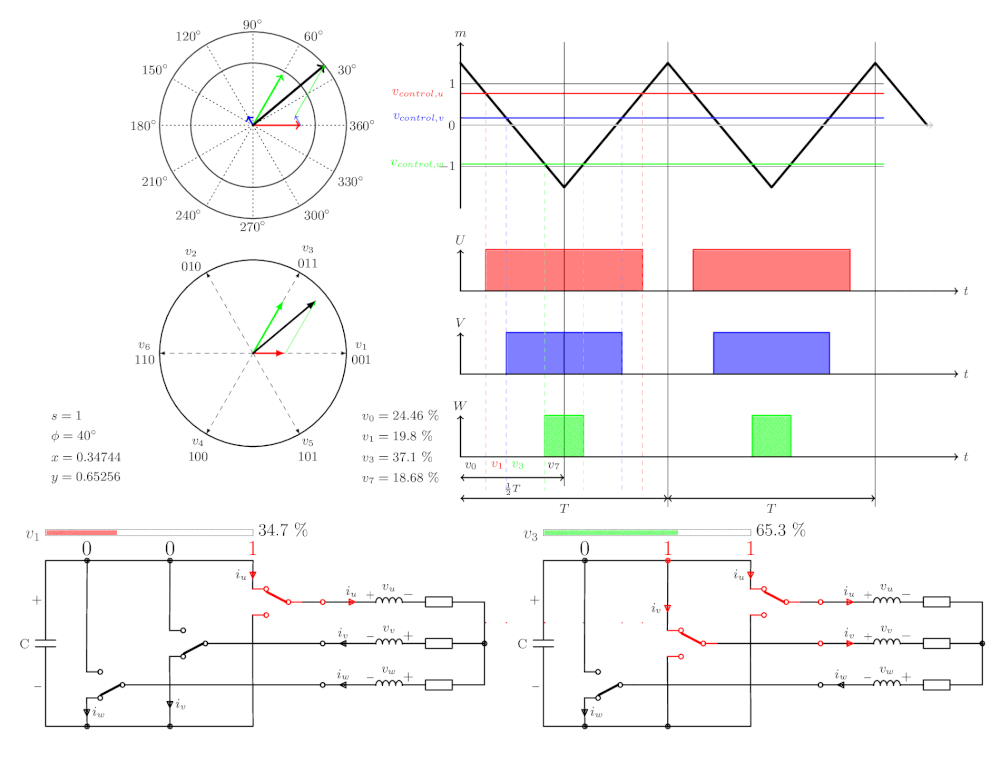
Example of 2399-ta-tb above, calculate the percentages of u1 and u3
: u1 = 1.154700538*0.86*2399*sind(60-40)/4799
u3 = 1.154700538*0.86*2399*sind(40)/4799
The actual calculation method of timer compare register data
is to generate a 0-60 degree lookup table, 2000 points, Q15 fixed point number
#include
#include
#include
void main() {
double x,p,y,i;
int jiaodu,rr,ii,n;
n = 60;
for(i=0;i
{
p = i*3.1415926536897932384626/180;
x = (sin(p)* cos(0))/ (sin(1.0471975) * cos(0));
y = (cos(p) - (x * cos(1.0471975))) / cos(0);
rr = x*0x8000;
ii = y*0x8000;
//printf ("%f,%f
",x,y);
printf("0x%04X,0x%04X,", rr,ii);
}
printf("
");
Retrieve X and Y values for 0-60 degrees from a lookup table:
x*2399= u1
y*2399= u3
2399-u1-u3 = zero vector
In the actual program, I modified 2399 to 2048 for calculation. This ensures the PWM duty cycle doesn't exceed the maximum. From
0 to 60 degrees, the timer compare register values are calculated:
W phase calculation: zero vector divided by 2;
U phase calculation: (U1 vector) plus (U3 vector) plus (zero vector divided by 2);
V phase calculation: (U3 vector) plus (zero vector divided by 2);
60 to 120 degrees : W phase calculation: (zero vector
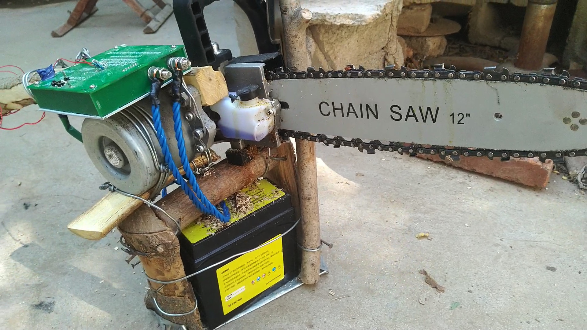
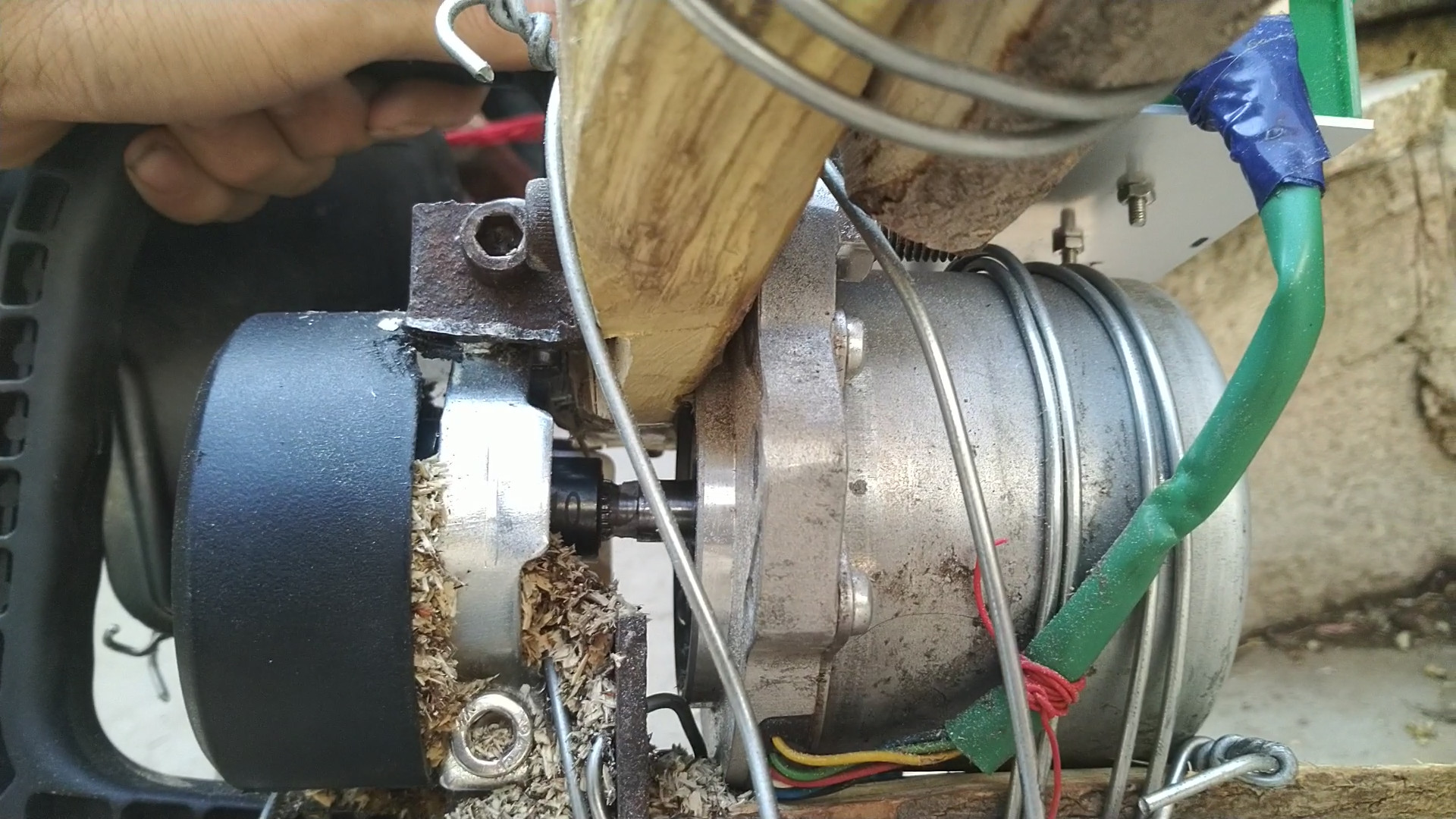
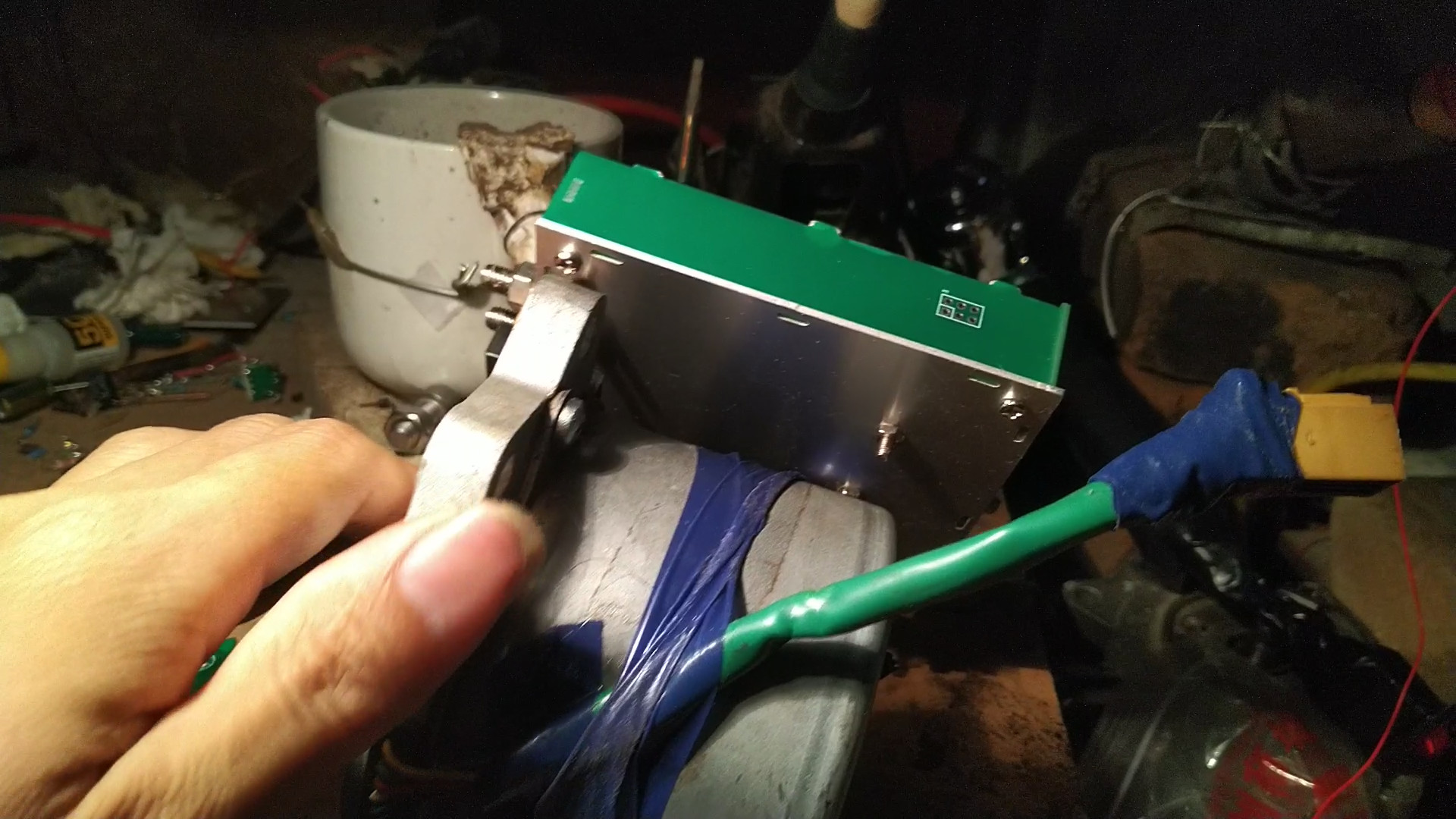
divided by 2) ; U phase calculation: (U1 vector) plus (zero vector divided by 2) ; V phase calculation: (timer maximum count 2399) minus (zero vector divided by 2). The remaining angles are directly obtained by swapping the UVW registers. Refer to the partition diagram for different switch combinations. The SVPWM electrical angle is 90 degrees ahead of the rotor measured by the rotary transformer. This way, speed adjustment only requires controlling the modulation ratio. Precise control of position and speed requires controlling the modulation ratio. The electric chainsaw used to modify the motor for the copper pillars in the controller assembly is used to verify whether the controller can be connected to the motor bushing using a modified electric chainsaw kit . A 10mm screwdriver is needed; the motor shaft is 10.8mm, so a 10.5mm drill bit can be used to enlarge the hole. [Controller actual product image]


 京公网安备 11010802033920号

 1MC0C0-030-3365-001.7-00-AD-00-0


