 Some contents of this project refer to the official case of Liangshanpai oscilloscope [oscilloscope expansion board], and supplement and improve it in many aspects to realize the functions of rechargeable portability, dual-channel signal acquisition, 4.3-inch large screen, full touch human-computer interaction, serial port signal viewing (supports Chinese characters) etc.
 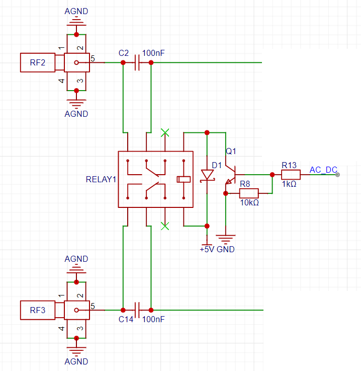 2. Analog Front-End Circuit:
 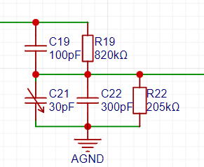 Signal Gain Processing and Vertical Shift Circuit:
 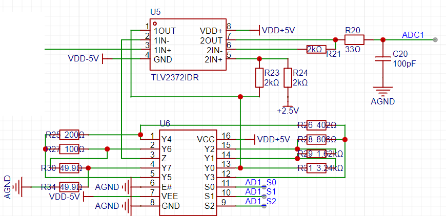 Signal Generator Circuit.
 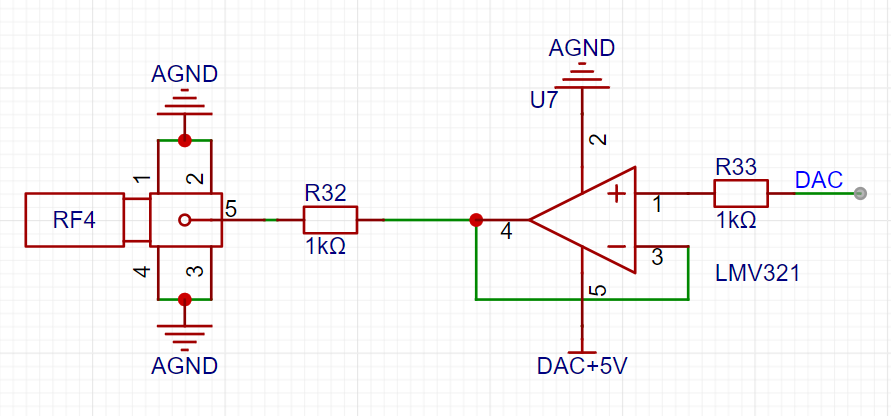 3. Power Supply Circuit
 A CJ431 generates 2.5V as the reference voltage for the microcontroller's ADC. Note that the default reference voltage for the Liangshanpai ADC is 3.3V. Therefore, it is absolutely essential to remove the 0-ohm jumper resistor for the corresponding A3.3V AGND on the Liangshanpai; otherwise, the measured data will be incorrect, and the circuit may even be damaged.
 An ME2159AM6G is used to boost the lithium battery voltage to 5V.
  The lithium battery charging management uses an LP4056HSPF. During charging, an LED will light up to indicate that charging is in progress; the LED will turn off when charging is complete. Due to space constraints, this project uses a 3mm thick, 50mm*60mm 1200mAh lithium battery to power the entire system. Hot melt adhesive is used to install it between the PCB and the RGB screen.
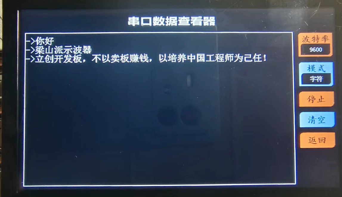
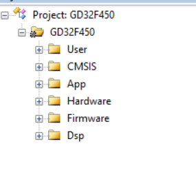
 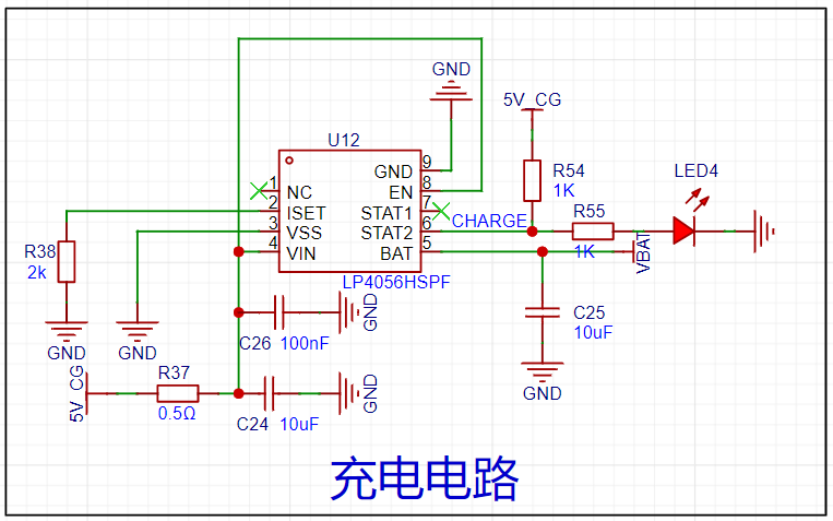 ( See Taobao shopping cart link: 77₤WEYTWPyGCsC₤ https://m.tb.cn/h.5uFXj1X CZ3460) I've shared some awesome content with you, come check it out! 4. RGB Screen: This project uses the 4.3-inch RGB screen that comes with the LCSC development board, with an 800*480 pixel resolution, providing a detailed display. Since the LCSC board has a built-in RGB interface, the hardware circuitry does not need to be designed separately. Purchase Link: https://item.szlcsc.com/8351841.html?t=1708862395529&s=1708862395529 5. PCB Design Instructions: Because the width of the 4.3-inch RGB screen exceeds 10cm, the width of the board outline will be shortened to within 10cm to ensure free prototyping. This project's PCB uses a double-layer PCB layout, employing two ground planes, AGND and GND, which are connected by a 0-ohm resistor. LED4 is a charging indicator light, placed near the edge of the board outline. When charging is initiated, the LED lights up; when charging is complete, the LED turns off. Simultaneously, when the board is powered on, charging details can be viewed on the battery icon at the top of the screen. The PCB physical image and interface function descriptions are as follows . A base plate dimension drawing is provided in another PCB file. An acrylic base plate can be customized, and copper pillars can be used to fix it to the back for protection. Function Usage Instructions: 1. Oscilloscope Function Description: The overall UI interface is shown in the figure. All human-computer interaction uses a touch screen, making operation more convenient. Note that the noise level of the sine wave shown in this image is quite high. This is because the entire system was powered by a computer's USB port, and the ripple from the USB power supply is likely large, causing some jitter in the data converted by the ADC. However, this phenomenon is much better when powered by a lithium battery! Observing the UI interface, the top left corner displays the battery level; next is the AUTO button. When the waveform display density is too dense or too sparse, pressing the AUTO button will automatically adjust the ADC sampling rate and vertical voltage gain to adjust the waveform to a suitable display state; the MEASURE button displays the signal acquisition from two channels in a small window; the RUN button starts or pauses sampling; the FFT button displays the spectrum (amplitude spectrum) of the Fast Fourier Transform for the current channel; the UART button switches the serial data viewer interface; pressing the OUT button displays the signal generator window, where the output signal type, frequency, and peak-to-peak value can be adjusted; the right side of the screen has buttons for adjusting the oscilloscope signal acquisition parameters; the two sliders on the left and right can adjust the vertical offset and trigger threshold of the waveform respectively; finally, there is a rotation button in the lower left corner, which rotates the screen. 2. Serial Port Data Viewer Function Description: I have integrated the functions of a serial port assistant from a computer into this instrument. It allows adjustment of the baud rate and different data parsing and display modes, making the serial port assistant portable. In character mode, in addition to receiving ASCII characters, it also receives and displays arbitrary Chinese characters; HEX mode displays received data in hexadecimal format; in waveform mode, the transmitter sends frames in the format "x,x,x,x", which this instrument can parse into waveforms, supporting up to six channels of floating-point waveform parsing (theoretically ten channels are also possible, but the final result may have bugs, as ten channels of data would result in a very long serial port data). An attached Python program generates six sine wave strings and sends them to the serial port, which can be used to test the waveform mode of the serial port data viewer. Software Code Description: 1. Project Structure : The App folder contains oscilloscope function code files, serial port data viewer function code files, and signal generator function code files. The Hardware folder contains various driver files. 2. Parameters
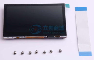


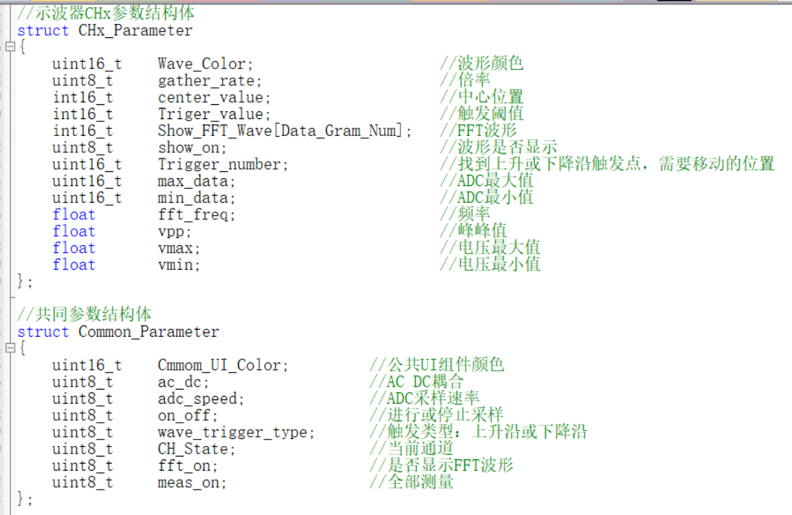 The Init_Oscilloscope function allows for convenient initialization of parameters such as sampling channel waveform color, initial sampling rate, initial signal gain, and AC_DC.
 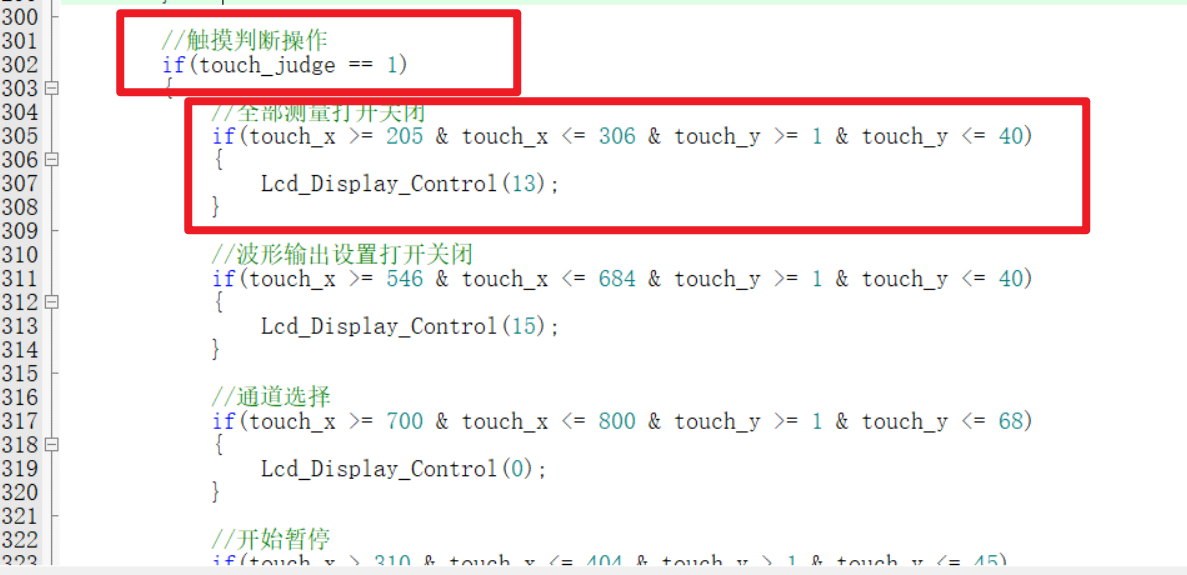 4. The method for receiving and displaying Chinese data in the serial port data viewer
  The steps for flashing the font into the SPI_Flash are simple. Just prepare a 16G or 32G TF card (other capacities haven't been tested, so I don't know if they will work), insert it into a card reader and connect it to the computer. Create a folder named FONT in the root directory of the TF card, decompress the font file (provided in the attachment) and store it there. Then insert the TF card into the TF card slot of the Liangshanpai board, flash the Chinese font flashing program in the attachment, and reset. Next, use a serial port assistant on the computer to monitor the real-time status of the font library writing process. The whole process takes about one or two minutes. When you receive "FLASH font_init success!", the font library writing is complete, and the serial port data viewer can then receive and display Chinese data!
  5. Screen Refresh
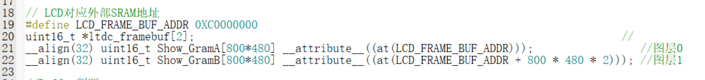
 Finally
All reference designs on this site are sourced from major semiconductor manufacturers or collected online for learning and research. The copyright belongs to the semiconductor manufacturer or the original author. If you believe that the reference design of this site infringes upon your relevant rights and interests, please send us a rights notice. As a neutral platform service provider, we will take measures to delete the relevant content in accordance with relevant laws after receiving the relevant notice from the rights holder. Please send relevant notifications to email: bbs_service@eeworld.com.cn.
It is your responsibility to test the circuit yourself and determine its suitability for you. EEWorld will not be liable for direct, indirect, special, incidental, consequential or punitive damages arising from any cause or anything connected to any reference design used.
Supported by EEWorld Datasheet
EEWorld
subscription
account

EEWorld
service
account

Automotive
development
community

Robot
development
community

About Us Customer Service Contact Information Datasheet Sitemap LatestNews


Room 1530, 15th Floor, Building B,
No.18 Zhongguancun Street,
Haidian District,
Beijing, Postal Code: 100190
China
Telephone: 008610 8235 0740
 京公网安备 11010802033920号

 1016
1016


