Background:
The Spartan6 series FPGAs are practically obsolete, with only the outdated ISE development environment and a lack of many modern FPGA features. Their cost-effectiveness is far inferior to the ZYNQ7010. Therefore, a replica is not recommended.
The reason for making this board was simply because I saw it while browsing a shopping website; it was only 13 yuan per board. Thinking I wouldn't lose out, I bought two to play around with, focusing on a vintage and old-school aesthetic. I also thought that open-sourcing it might help some people who are forced to use Spartan6 for various reasons.
Update 1: DDR verification successful. DDR debugging tutorial added, see "5. Post-assembly testing".
References:
Schematic diagram referenced Zhengdian Atom's S6 core board: http://www.openedv.com/docs/boards/fpga/zdyz_S6xtb.html
Board layout and I/O referenced @上电冒烟's ZYNQ core board (this is the one worth replicating, not my old, unusable board): https://oshwhub.com/z_star/zynq7020-core-board-and-various-rf-modules
Because ISE is relatively old, the final usable solution is FT232H + Digilent firmware (also compatible with Vivado).
The FT232 downloader is modified from the open-source project: https://oshwhub.com/parus_major/xilinx-hs-fpga-xia-zai-qi.
The downloader firmware uses Digilent firmware extracted by TT: https://www.bilibili.com/video/BV1nT4y1L7uE.
Table of Contents:
1. Design Ideas/IO Allocation
2. Power Supply/Decoupling
3. PCB Design
4. Assembly and Soldering
5. Post-Assembly Testing
6. Summary
7. BOM Cost.
Design Ideas/IO Allocation:
The main consideration in FPGA hardware design is how to allocate IO resources for each bank. My main purpose in making this board is to serve future high-speed circuit projects. Therefore, the design will focus on bringing out high-speed IO (low-voltage high-speed IO such as LVDS)
. Although JLC can now get 6-layer immersion gold boards for free (JLC is awesome), I personally still want to use a 4-layer design, mainly to explore a low-cost, low-complexity PCB design that can also achieve a high operating speed.
Finally, in this design, I abandoned the onboard FLASH chip because I only discovered a pin conflict after completing the I/O rollout (lol). Therefore, this board can only load programs via JTAG and disappears upon power-off. Thus, it's only suitable for debugging applications.
Based on the above considerations, the I/O allocation is as follows:
Bank 2: Uses a 2.5V power supply, all pins are differential pairs, totaling 18 pairs, of which 17 are of equal length, used as standard LVDS input/output.
Bank 0: Uses a 3.3V power supply, all pins are differential pairs, totaling 20 pairs, all of equal length, used as general I/O input/output.
Bank 3: Uses a 3.3V power supply, partially exposed, used as I/O ports for onboard peripherals and to expand the number of I/O ports in Bank 0.
Bank 1: Uses a 1.5V power supply, used to connect to the DDR3 chip.
Note: After writing this part, I realized that perhaps the power supply voltages of Bank 2 and Bank 0 could be swapped, so that Bank 0 could be entirely used as a 2.5V LVDS interface. Although the VCCAUX power supply is on the same track as Bank0 in the design, the official datasheet states that VCCAUX can use a 2.5V supply voltage. However, the JTAG voltage will drop to the 2.5V standard, requiring a downloader with a buffer.
When designing for DDR3, be careful not to miss any traces, as several signals are easily overlooked: the VREF reference voltage for the FPGA, and the RZQ resistor used for DDR calibration of the FPGA.
There aren't many onboard peripherals: a user LED, a reset button, and a CH340C for serial communication.
Power supply/decoupling:
The classic EA3059, a single-chip four-channel solution, is sufficient for a small FPGA with 16K resources.
Regarding decoupling, although the number of capacitors seems small, simply following the official datasheet is sufficient. For this 16K chip, the officially recommended decoupling solution is to use a large capacitor (or a small one, since the surface mount capacity isn't that large) for each bank/voltage channel, then place two to three 4.7uF 0603 capacitors near the FPGA chip, and finally place two to three 470nF 0402 capacitors on the front and back of the chip.
PCB Design:
As mentioned at the beginning of the article, the goal this time is to challenge ourselves to achieve a high operating speed using only a four-layer board. Because the four-layer board has a relatively simple structure, there are only two considerations for the routing layers
: 1. High-speed lines can only be placed on the bottom and top layers, and the middle layers must ensure the integrity of the reference plane to allow for impedance control.
2. Power distribution and ground planes can only be placed on the middle two layers; otherwise, it's impossible to route them for BGA.
The design process went relatively smoothly, and the final four-layer result is as follows: the signal line width is 5mil, and the impedance is approximately 54 ohms based on impedance calculations. With appropriate widening, it can be controlled to 50. The DDR signal line vias are controlled to a maximum of two
. A small episode: I originally wanted to use two DDR chips, but after two days of trying, I found that it was extremely difficult to route the Bank3 memory pins with equal length when using a four-layer board. If any expert has successfully routed and made it usable, please share the design.
Another point is that the ODT and RST trace lengths of DDR3 are quite flexible. Considering that these two pins will not involve high-speed switching operations, I did not make them equal in length with other groups for the sake of routing convenience (if this statement is incorrect, please correct/criticize in the comments).
Top

layer inner layer: Ground layer

inner layer: Power
(Oops, I just realized that I cut three areas for the reference plane of the lower signal lines (sad)).
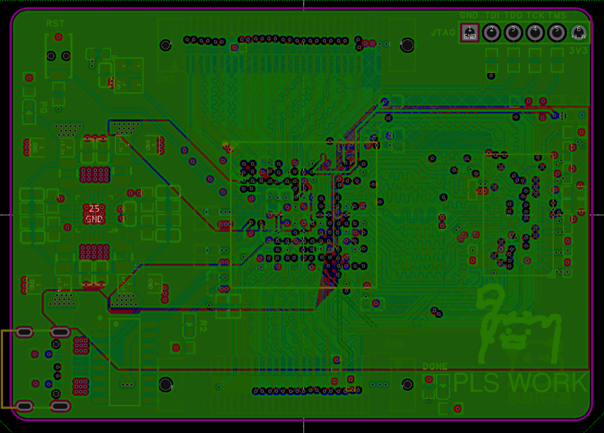
Bottom layer

assembly and soldering:
There should not be much to say about this. The soldering sequence is mainly: power supply circuit---test---solder the main BGA chip---test---solder DDR---solder passive components---test (testing method is below).
Soldering the BGA may be the most daunting part. I personally think that soldering the BGA requires boldness and meticulousness.
Being "bold" means the temperature can't be too low, because it's a four-layer board with a small chip area, so preheating with a hot plate isn't necessary, but the hot air gun temperature can't be too low. My soldering parameters are: a popular small hot air gun from Taobao + 360 degrees + 6 wind speeds (medium to high) + no nozzle + air nozzle distance from the chip is one finger's width + continuous and even heating for 3.5 minutes.
During my first soldering session, I was worried that the hot air gun temperature would be too high and burn the chip. However, after consulting with several experienced people, I learned that digital chips are actually quite difficult to damage with a hot air gun; the real concern should be the PCB and the chip substrate. Since the chip used this time was encapsulated with black glue, the only real concern was the PCB.
To prevent the PCB from being damaged by the heat, you can add more solder paste around the pads or cover them with aluminum foil/high-temperature tape. The solder resist may turn yellow during soldering, but it's not a major problem.
As for being careful, that refers to the precautions mentioned above. For everything else, just heat it up vigorously.
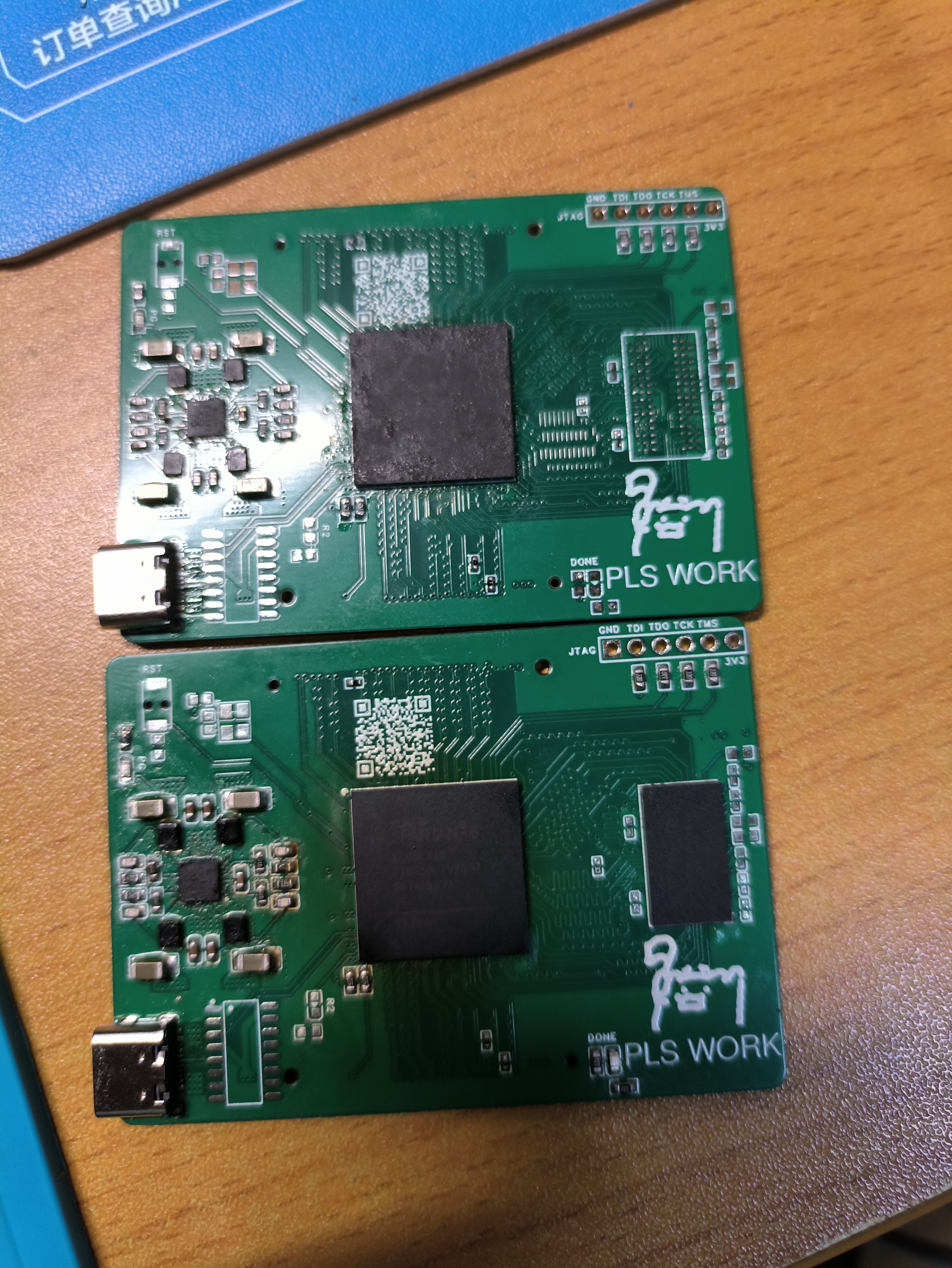
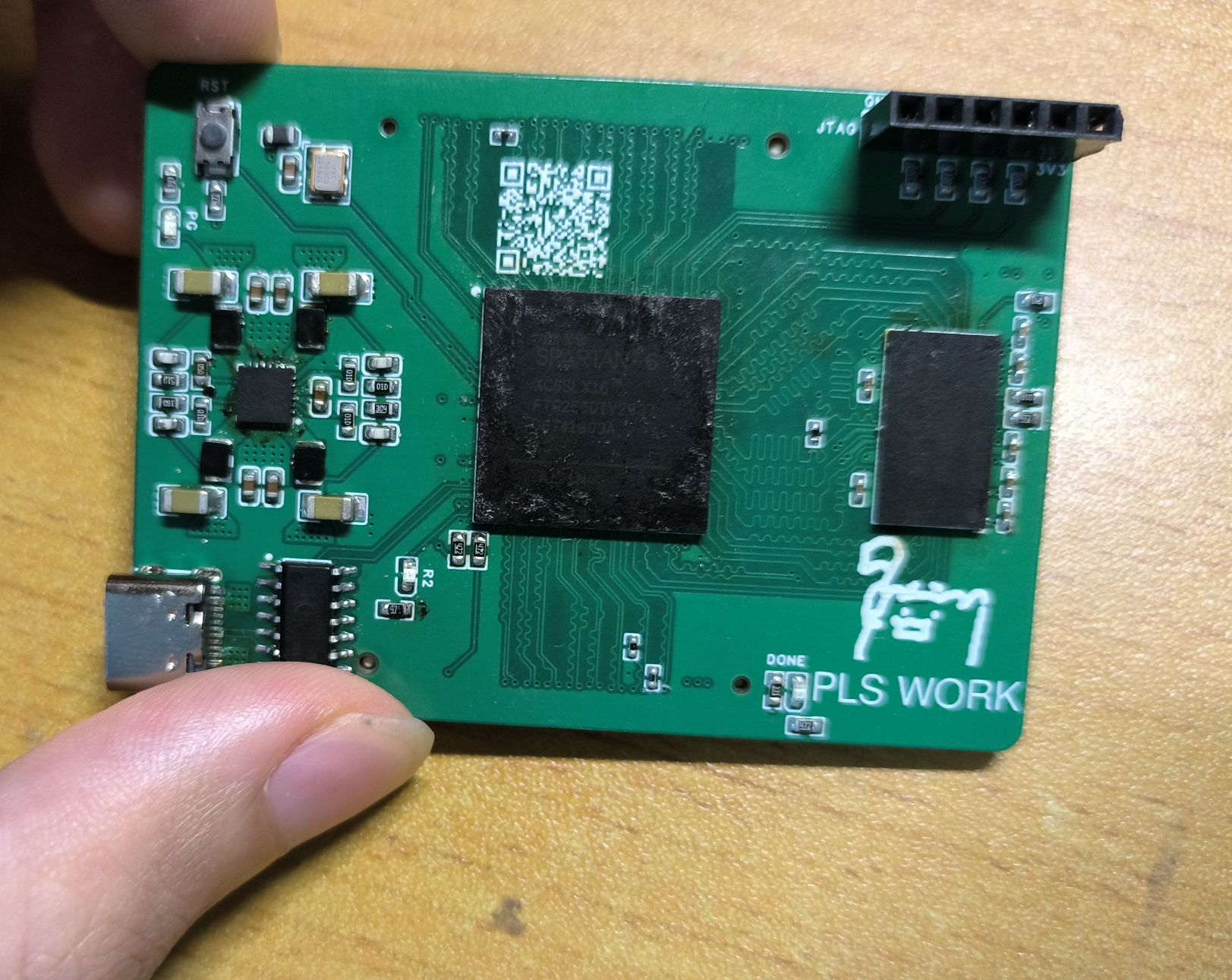
After soldering, allow the board to cool naturally to prevent the internal chips from expanding and contracting too quickly due to temperature changes, which could cause damage. Below are the results of my two separate soldering attempts on the two boards. Both boards functioned correctly:
First attempt (bottom) Second attempt (top)
Post-assembly testing:
Method for checking pin soldering without power (only the FPGA was soldered at this point, DDR was not installed).
For this FPGA model, my testing method is as follows:
Set the multimeter to resistance/diode mode, ground the negative terminal, and probe each IO pin (including JTAG) with the positive terminal. You should get the following values:
Resistance to ground: approximately 5.6KΩ
Diode value: approximately 0.3V
This method can check if the FPGA's IO pins are soldered correctly.
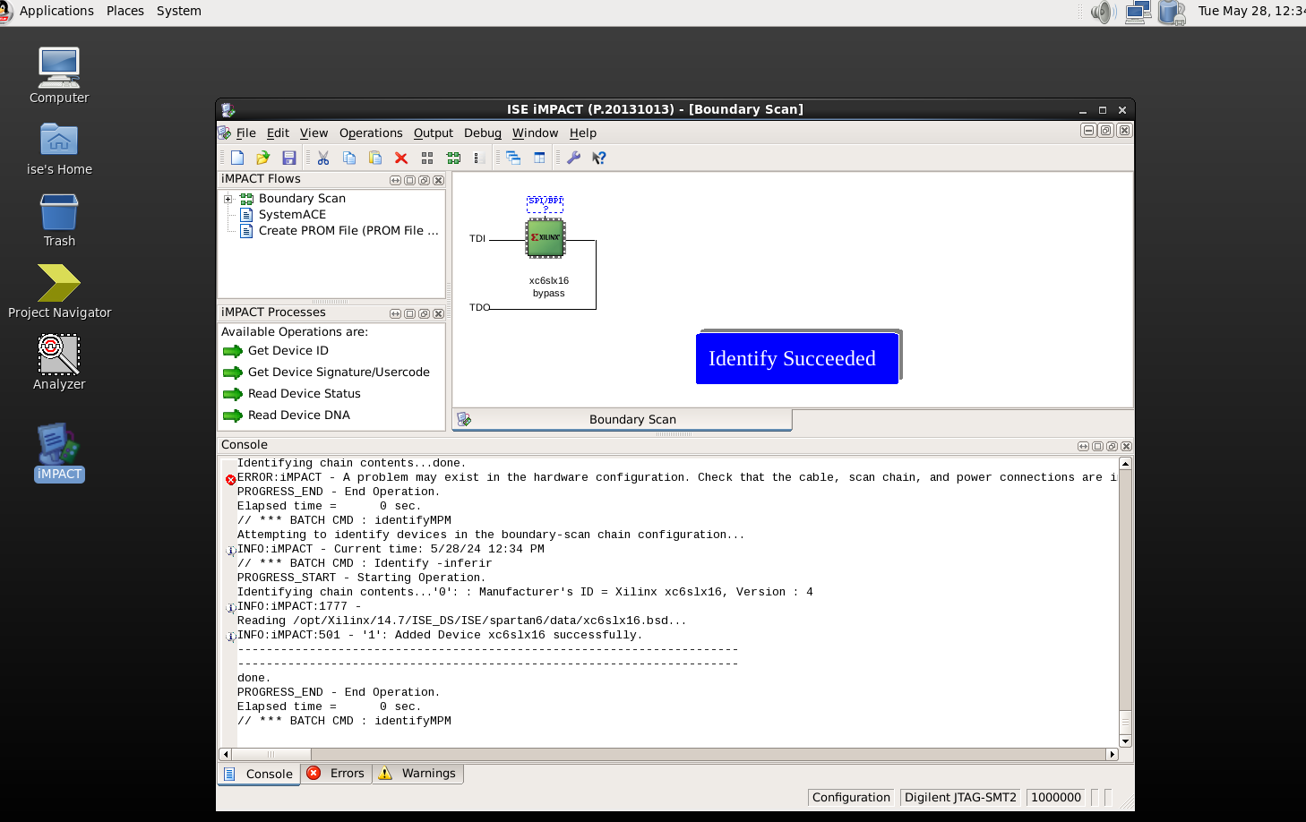
If the above tests are successful, you can use JTAG to check if the chip is working properly. This step should be self-explanatory; ISE's iMPACT or Vivado's hardware manager can detect it (although you can't use Vivado for S6 development).
DDR testing method:
This is both simple and complex. It's simple because you don't need to write Verilog to test it, but it's complex because there are quite a few setup steps. However, there are also detailed video tutorials online
. The official manual numbers are UG416 and UG388.
The specific steps are as follows: 1. Create a new DDR IP core, 2. Fill in the DDR chip parameters according to the manual, 3. Modify the user constraint file, 4. Modify the PLL related parameters, 5. Modify the sample project, 6. Synthesize and generate the file, and use ILA to check if it is normal.
ISE is very old and may have problems on newer systems. Here, we are using Windows 10, and ISE and the toolchain are running in 32-bit versions.
In addition, please set the address of ISE and its toolchain in the system environment variables in advance, otherwise there will be errors, as shown in the figure below:

The specific steps are as follows:
1. Create a new DDR IP core
. Create a new ISE project, select the corresponding device, open the IP core generation tool, find MIG Spartan6, and create it (this should not need to be taught step by step).
Note that MCB should be selected as C1, and then proceed to the next step to fill in the chip information.
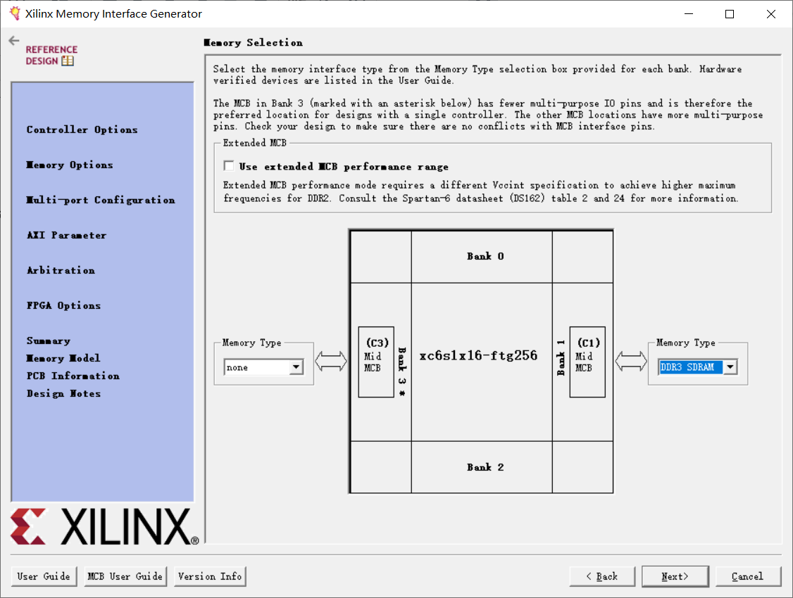
2. Fill in the DDR chip parameters according to the manual.
Because ISE is too old, there are no chips that can be directly matched to our board, and the DDR parameter settings are crucial (especially various timings), so we can only create the corresponding model ourselves.
Select the chip shown in the image as the base model, then click "Create Custom Part"
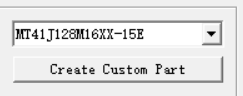
and modify the parameters in the box as shown in the image below (just enter any name).

These values are from the manual; if you are using a different chip, you need to refer to the manual yourself. The parameters here are only applicable to the Micron 4Gb chip I have.
After creating the chip model, save it and click Next until you see this interface. We will only leave one read/write interface, as it is only for testing purposes.

Then click Next again until you reach FPGA Option. We need to change the system clock type to single-ended and enable the Debug option to acquire chip waveforms.
There are also RZQ and ZIO pins, which were considered during the design; keep the default settings.

Then keep clicking Next until the IP is successfully generated.
3. Generating the ISE Project:
After successfully generating the IP core, close the software, find the script in the project directory
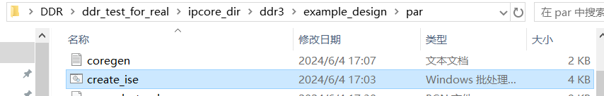
, double-click to run it, and wait patiently. A test sample ISE project file will be generated.

Note: If the run fails, please check if the toolchain directory has been added to the environment variables.
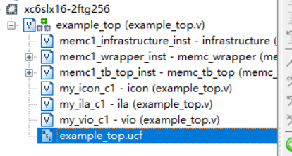
4. Modifying the User Constraint File
: Open this project. The first thing to do is modify the relevant pin and voltage parameters. Therefore, find the example_top.ucf file and open it.
The main places that need to be modified are:
I. Change the VCCAUX voltage to 3.3V.

II. Change the user clock input frequency to 50MHz (20ns).

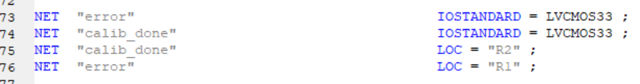
III. Change the voltage and IO of the calibration status LED (R1 of the error LED is not actually connected to anything, but it is still modified. R2 is connected to calib_done, and the calibration passes and lights up).
IV. Modify the voltage and IO of the clock input and reset input.
First, the IO voltage and pull-low.
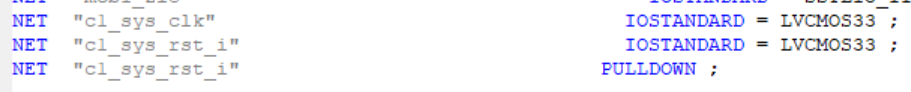
Note that you should not ignore the PULLDOWN. Although the name says "active low", it is actually "active high". If it is not pulled low, it will cause the system to run in the reset state.
I searched online for a long time and only found one article mentioning this. It is quite strange. Has no one verified this on the board?
Next, regarding the I/O ports,

note that RST_I is intentionally connected to an empty pin. Due to the factors mentioned above, the onboard RST is actually unusable (by default, it's pulled high). I was concerned that the FPGA's internal pull-low sinking capability wouldn't be sufficient, so I didn't connect RST to an external port.
F1 is the interface for the onboard 50MHz crystal oscillator .
5. Modifying PLL-related parameters:
To make the DDR run at 300MHz, we need to modify the PLL parameters. Locate the example_top.v file in the following location

, then find the lines shown in the image and change them to the parameters shown in the image.

As for each clock parameter, the official manual provides corresponding explanations; only a brief explanation is given here.
OUT0 and OUT1, operating at the same frequency but 180° out of phase, serve as the DDR master clock. Their operating frequency should be twice the actual DDR clock frequency. That is, to achieve an external DDR operating frequency of 325MHz, these two clocks should have frequencies of 650MHz.
OUT2 is the user clock; its exact usage is unclear.
OUT3 is the calibration clock, typically in the 50-100MHz range.
BOUT_MULT is the PLL multiplier parameter
. DIVCLK_DIVIDE is the division factor before inputting the PLL reference clock (i.e., the external input clock).
My final selected parameters were: inputting a 50MHz clock, first dividing it by 2, then multiplying it by 25 to 625MHz, and then dividing the calibration clock by 10 (62.5MHz).
Therefore, theoretically, the final DDR operating speed is 312.5MHz. Actual measurements will be provided later.
Note: The above multiplier parameters were generated using the ISE PLL calculation tool. See the Clocking section of manual UG388 for details; it explains this quite clearly.
6. Modify the example project:
In the example_top.v file, find the following section
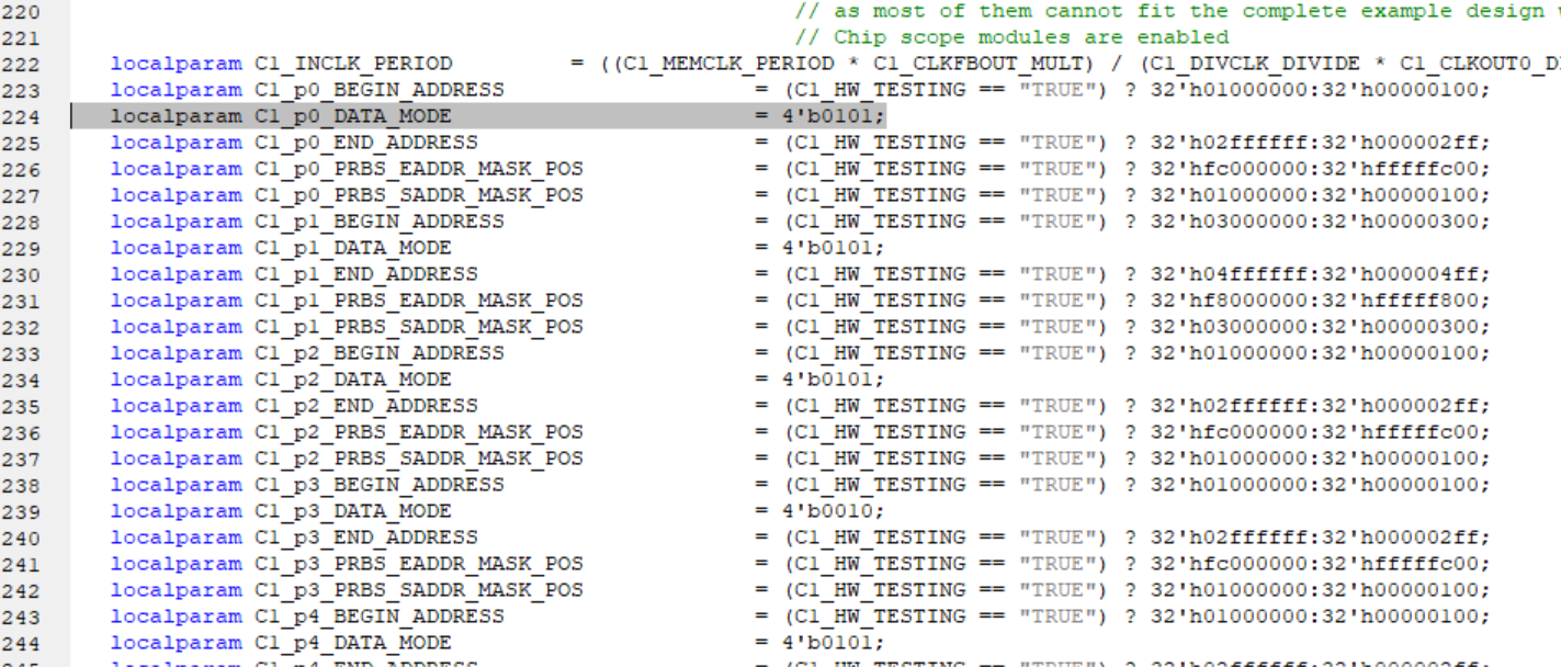
and change all DATA_MODE values to 0101. This is used to configure the data generator. With the data generator, we can test whether DDR writes are normal.
DATA_MODE has several other modes; see the Modifying the Example Design section of UG416 for details. Change this to 0101. During testing, the following data should be generated:

7. Synthesize and generate the file. Use ILA to check if it is normal.
Finally, the sample is ready. Next, we need to complete the three-step synthesis process. After successfully generating the bitstream, open ChipScope at the bottom.

Open ChipScope,
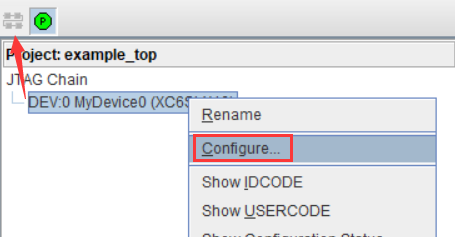
select the generated file, and then OK. Load the program onto the FPGA. If all goes well, the R2 LED on the board will light up.

Then collect the waveform and magnify it to observe the read data.
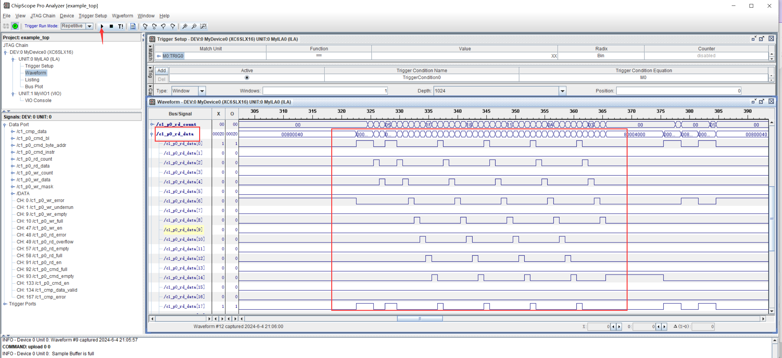
The clock frequency measured by the oscilloscope (limited by bandwidth, the amplitude is incorrect) is exactly 312.5MHz.

Summary: The finished product is shown
in the picture below:

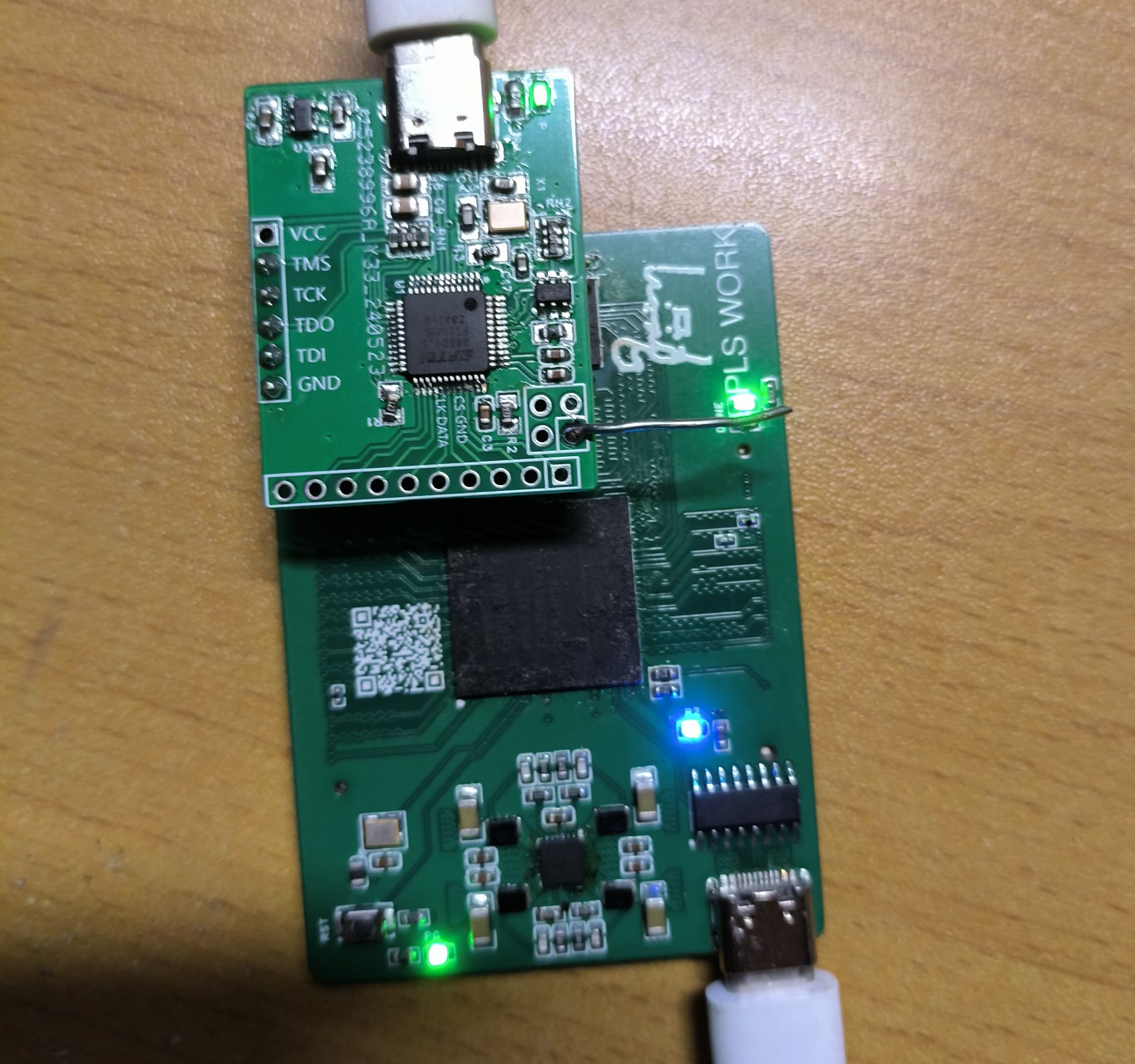
(The LED in the picture is lit up when DDR3 calibration is passed)
BOM cost:
PCB: Free
FPGA: 13 yuan
4Gb memory chips: 9 yuan
Power supply and its peripheral accessories: about 8 yuan
BTB male connector: 4 yuan (a pair)
Other miscellaneous things: Let's say 10 yuan
Finally, I would like to ask all the experts to give me more guidance. Whether it is tactful or direct criticism, it is very welcome. After all, I can learn something from it.


 京公网安备 11010802033920号

 177-710-5-21CS6J1-24RAN


