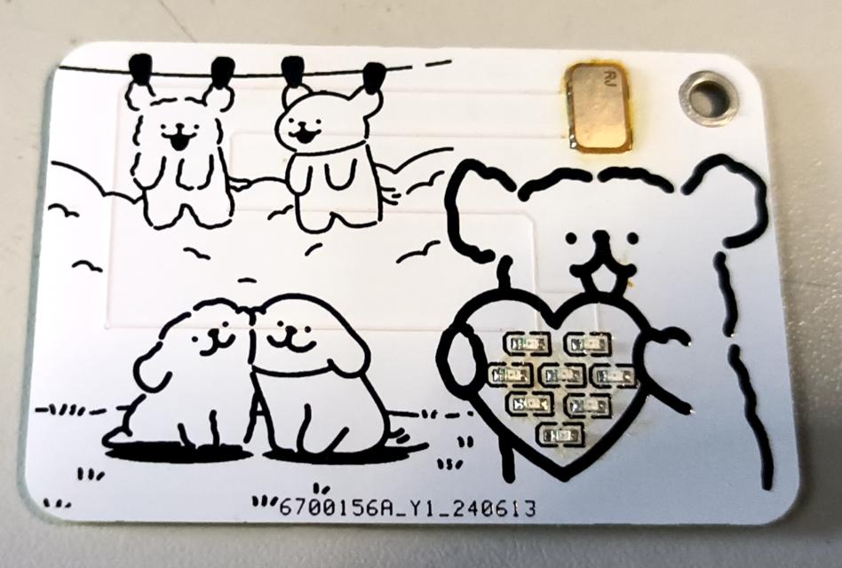
The LED light on the line-shaped puppy NFC card needs to be the 0806 model. Care should be taken when soldering it. The chip on it is the same NFC chip found on a regular card.
This smart humidifier uses an STM32F103 main controller and integrates a motor driver, humidifier, water level monitoring, air quality detection, and OLED display module. It efficiently humidifies, monitors air quality in real time and displays humidity, temperature, air quality index, and water level status. It is easy to operate and improves the home environment.
This smart humidifier integrates multiple modules to provide efficient and intelligent humidification and air quality monitoring. Below is a detailed introduction to each module:
Main Control Module: The
STM32F103 microcontroller serves as the core control unit of the smart humidifier, coordinating and managing the operation of all functional modules. Its powerful processing capabilities and rich peripheral interfaces ensure stable and efficient operation.
Motor Drive Module:
This module drives the fan, which disperses the water mist generated by the atomizer over a greater distance, thus improving humidification. The motor drive module ensures stable fan operation and adjusts the fan speed as needed. Humidifier Module: This
is
the core functional module of the entire device, responsible for converting water into fine water mist and evenly distributing it in the air to achieve humidification. This module uses ultrasonic atomization technology to ensure a fine and uniform atomization effect.
Water Level Monitoring Module:
To ensure the normal operation of the humidifier and prevent dry burning, this module monitors the water level inside the humidifier in real time. When the water level is too low, the system will automatically remind the user to add water or directly stop the humidification function to protect the device. The
air quality monitoring module
detects the air quality in the environment. By monitoring air quality in real time, the smart humidifier can automatically adjust the humidification level according to environmental conditions, ensuring fresh and healthy indoor air.
The OLED display module
shows various real-time information, allowing users to intuitively understand the device's operating status and environmental parameters. Display content may include:
Features:
Intelligent Control: Precise control and coordination of various modules are achieved through an STM32F103 microcontroller.
High-Efficiency Humidification: Utilizing ultrasonic atomization technology, water mist is rapidly diffused into the air.
Air Quality Monitoring: Real-time monitoring of ambient air quality and automatic adjustment of humidification level based on the detection results.
Safety and Reliability: The water level monitoring module ensures the device operates within a safe water level range, preventing dry burning.
Real-Time Display: The OLED display provides an intuitive operating interface and real-time feedback, allowing users to easily understand the device's status.
This smart humidifier is not only powerful but also easy to operate, making it an ideal choice for improving the quality of your home environment.
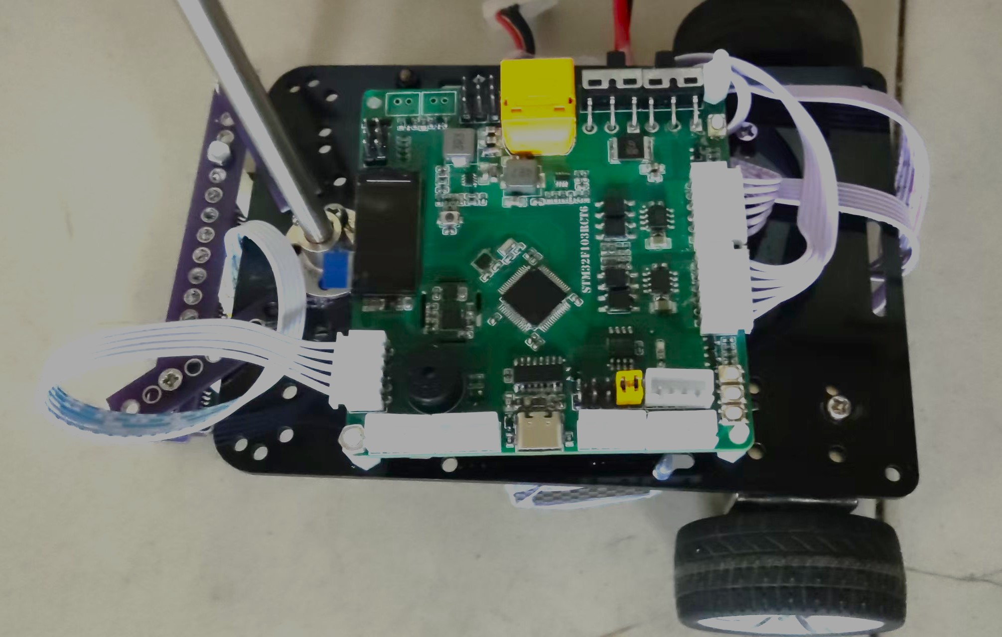
The goal of this design is to accomplish all the functions required for the electronics design competition on a single board.
Project Introduction:
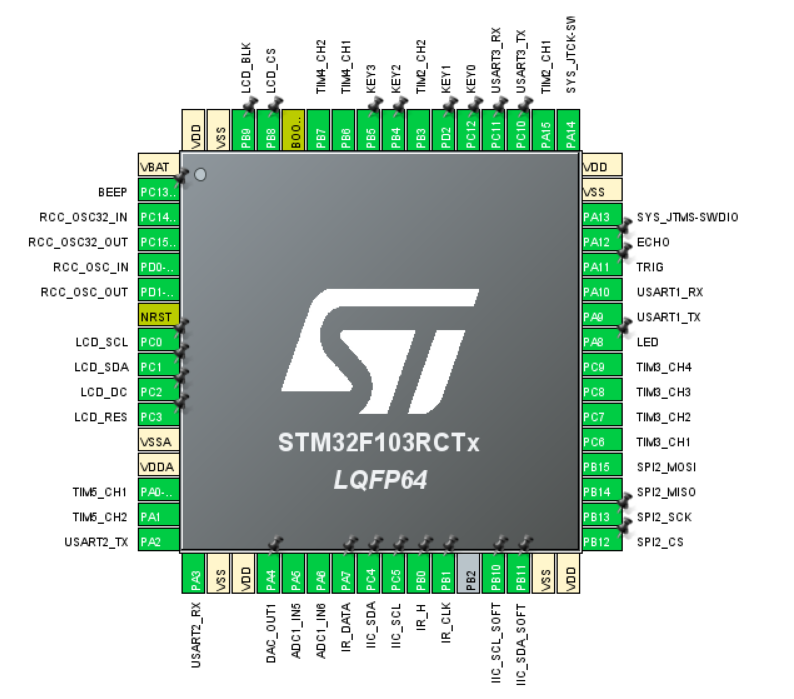
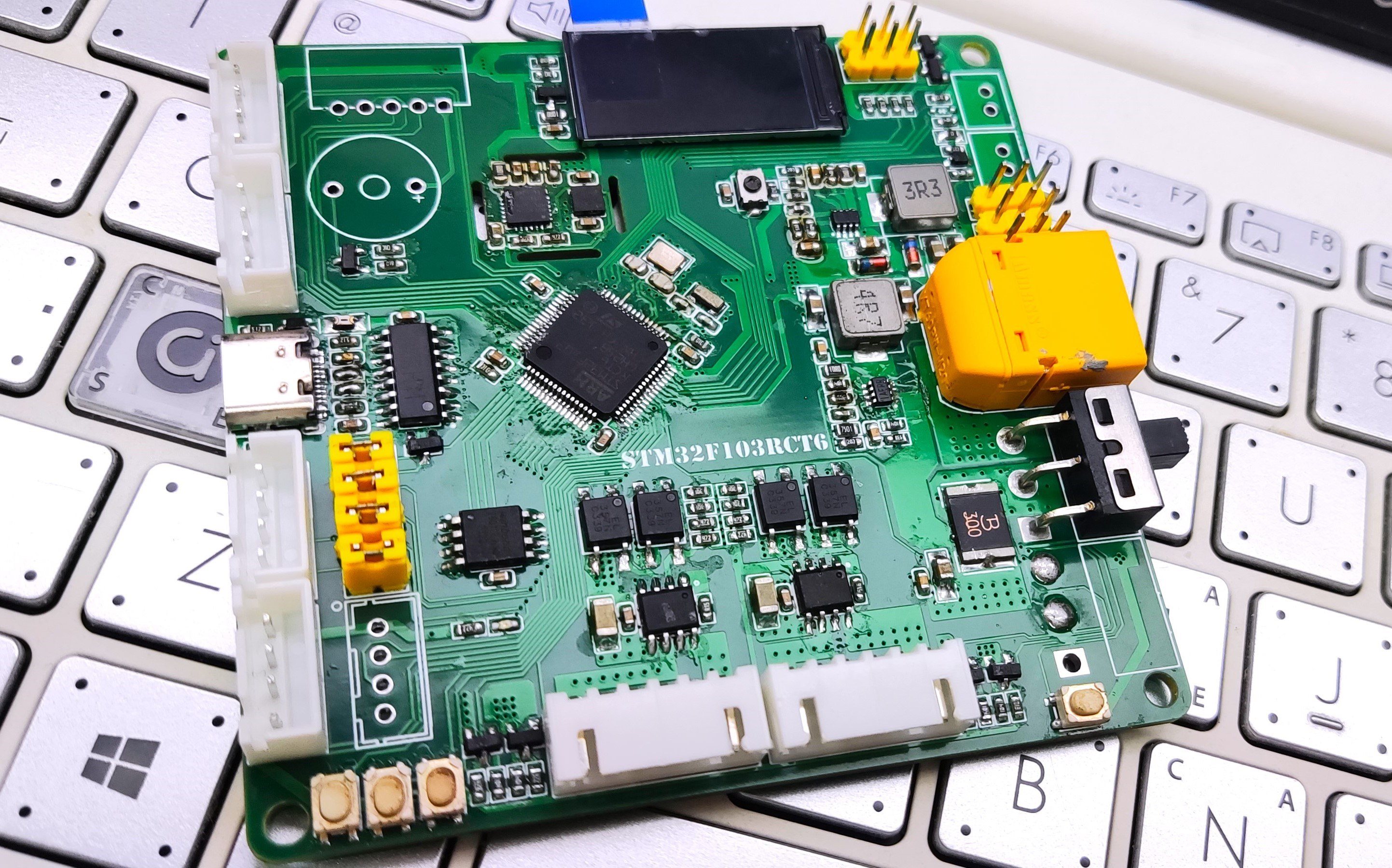
This is a control board that I started designing around this time last year. It was completed six months ago in preparation for the National Electronics Design Contest (NEDC). Before that, it went through four versions, but unfortunately, it wasn't used in the contest. Because I made many modifications and studied many excellent open-source projects, I avoided many pitfalls. Therefore, I'm open-sourcing it to provide reference for more students without guidance. The goal of this design is to complete all the functions required for the NEDC on a single board. It uses the STM32F103RCT6 microcontroller, utilizing almost all of its pins.
Supported functions:
Dual-channel voltage regulation, onboard daplink, dual encoder motors (with isolation), dual servos, TFT color screen, gyroscope, magnetometer, 4 buttons, 1 LED, external FLASH storage, active buzzer, two ADCs (1 external, 1 power supply), one DAC output, power header pinout, 1 IIC pinout, ultrasonic, line tracking, and 3 serial ports (one connected to daplink via a jumper). The microcontroller resource allocation

hardware introduction uses XT60 and ordinary terminal blocks for
the power supply
interface. The required interfaces can be soldered according to your own battery.
Both power supplies use MP2225 converters, converting VCC to 5V and 5V to 3.3V respectively.
VCC is used for the motors, and batteries of different voltages can be connected according to the motor's rated voltage. 5V is used for the two servo motors, and 3.3V is used for the onboard components and the microcontroller.
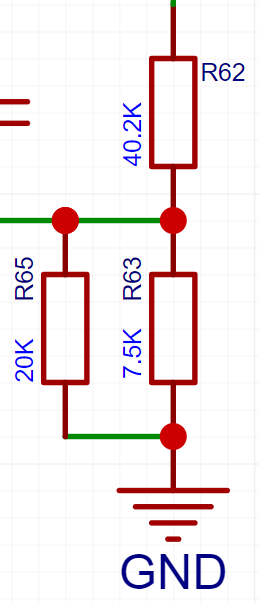
If the servo voltage is not 5V, it can be changed to the required voltage according to the following formula. A 1N5819 is connected in series between 5V and USB. Even if the voltage is changed to greater than 5V, plugging in USB will not damage the computer's USB port. When only USB power is supplied, the measured 5V voltage may be 4.7V, which is the normal diode voltage drop.
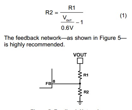
Two resistors are used in parallel here instead of one R2 in the formula. If you can buy resistors with the appropriate ratio, you can replace them yourself. Vout is the voltage you want to output to the servo motors. Here, a 5V resistor is used.
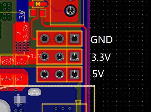
The board also provides external interfaces for 5V, 3.3V, and GND.
For the download section,
this project has an onboard daplink firmware, which is downloaded using a CH552. The firmware can be referenced from the Liangshanpai programmer.
https://oshwhub.com/lengyuefeng/a7c57e6d86bd47789178df3fda9219dc
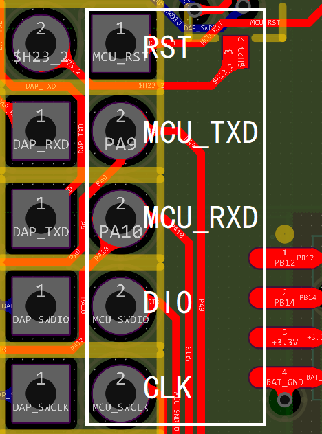
Connect the RCT6 to the UART1 and SWD ports via jumper caps. If you don't want to solder the CH552 or if it's damaged, you can first solder the header next to Type-C and use it for program downloading or serial communication. If the daplink detects the microcontroller but cannot download the program, remove the jumper cap connecting the programmer and the microcontroller MCU_RST. Resetting the programmer without connecting it will not have any effect.
The microcontroller used is an STM32F103RCT6, with the filter capacitors placed as close as possible to the power pins, and the crystal oscillator section grounded.
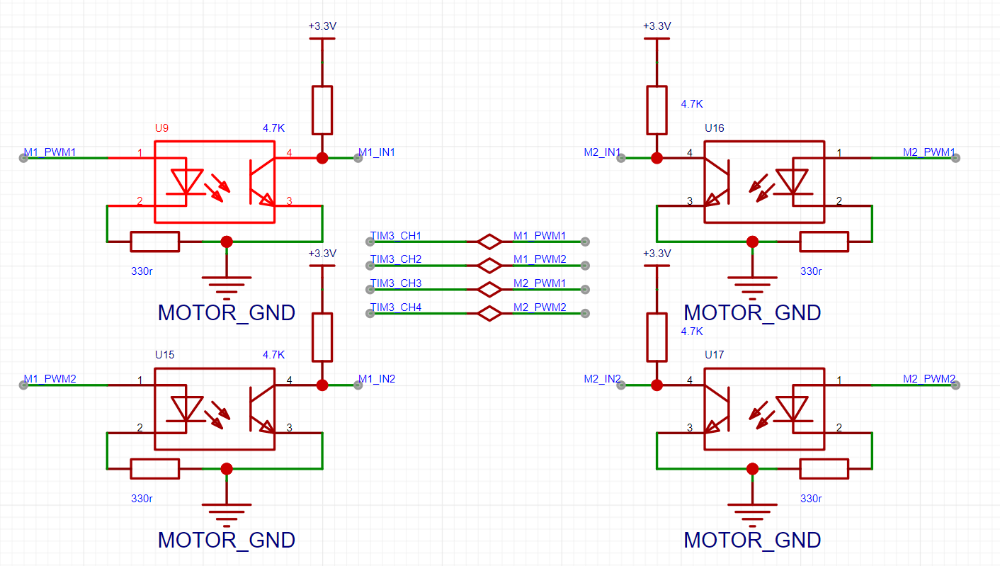
The motor uses an encoder motor, controlled by two AT8236 chips, and isolated using an EL357. The encoder is isolated by a transistor (I forget the exact reason, but it seems unnecessary; you could omit the transistor connection resistor and short pins 1 and 3).
For control, a four-channel PWM controller from a TIM3 chip is used to control the encoder motor.
Speed measurement uses encoder modes from TIM2 and TIM5 chips.

The servo motor's feedback resistor can be adjusted based on the servo's voltage. Two PWM channels from a TIM4 chip control

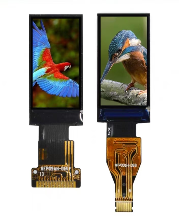
the screen, which is a 0.96-inch SPI protocol bare-screen soldered board with a resolution of 80*160. It costs only 3-4 yuan per piece, cheaper than buying an OLED screen directly, and the external circuitry is simple, meeting the display requirements. For displaying complex content, it is recommended to use serial port display directly. Note: Before soldering, carefully check the pin order on the silkscreen and the pin order on the screen to avoid reversing the soldering!
For control, software SPI is used (hardware SPI was not used because the microcontroller resources are somewhat limited, and since only data display is planned, high refresh rates are not required).

The gyroscope used is the MPU6050; there is plenty of documentation available online, including many open-source resources and tutorials. Because ST's hardware IIC function is not perfect, and a high detection frequency is not required, software IIC control is more suitable. During use, no good solution was found for the zero drift problem, but in actual use, there was only a small amount of zero drift at startup, which then stabilized and became negligible. Note: Without a hot air gun or other tools... Solder with caution on the hot plate.

The magnetometer uses a QMC5883, sharing one IIC channel with the gyroscope. I personally don't use it much, so you can choose to solder it selectively. Note: Solder with caution if you don't have a hot air gun or a hot plate.

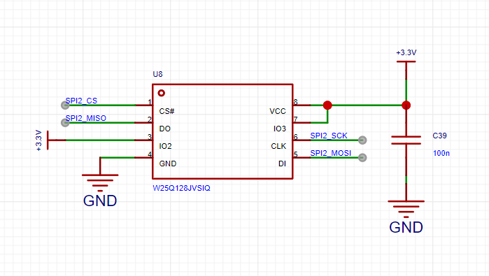
The storage section uses a W25Q128, using hardware SPI2 communication. If you don't need power-down storage, you don't need to solder it.
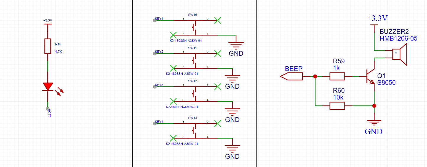
There is an onboard LED for status display, 4-way button input, and 1-way active buzzer (you can solder an unactive one, but I only need it to sound; an active one is easier to control).
Channel 5 of ADC1 is used to measure battery voltage, and channel 6 is used for external voltage detection. An external DAC is also connected for voltage output. Both ADC channels use resistor voltage dividers. In calculations, the voltage read by the ADC needs to be 11 times the voltage. Ground plane is used. 0R resistors were used for segmentation.

This project introduced three serial ports. UART1 is connected to the onboard daplink via a jumper cap. UART2 and UART3 can be used for communication between the wireless module and the OpenMV/K210, respectively. When there are not enough serial ports, the jumper cap on the onboard daplink's UART1 can be removed.

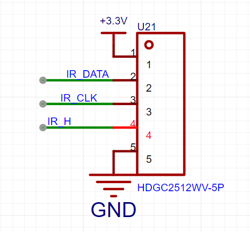
Due to the limited resources of the microcontroller, ordinary tracking modules would use many pins, so a parallel-to-serial conversion scheme was adopted. The onboard interface only uses three data lines, making control very simple and worry-free. It works well with tracking modules that include parallel-to-serial conversion (this is not necessary if only three-channel tracking is required).
Here is a recommended resource: https://oshwhub.com/xaiomao/infrared_track This solution offers 16-channel tracking at a low cost, and using photodiodes to detect the light source allows for easy replacement of the desired color detection. Compared to online options that cost several times more, this solution is very user-friendly.
Simple I/O control is used here; an ultrasonic module could be connected for obstacle avoidance and distance measurement. However, ultrasonic modules haven't been used in recent years' electronics design competitions, so this is still a good learning resource.

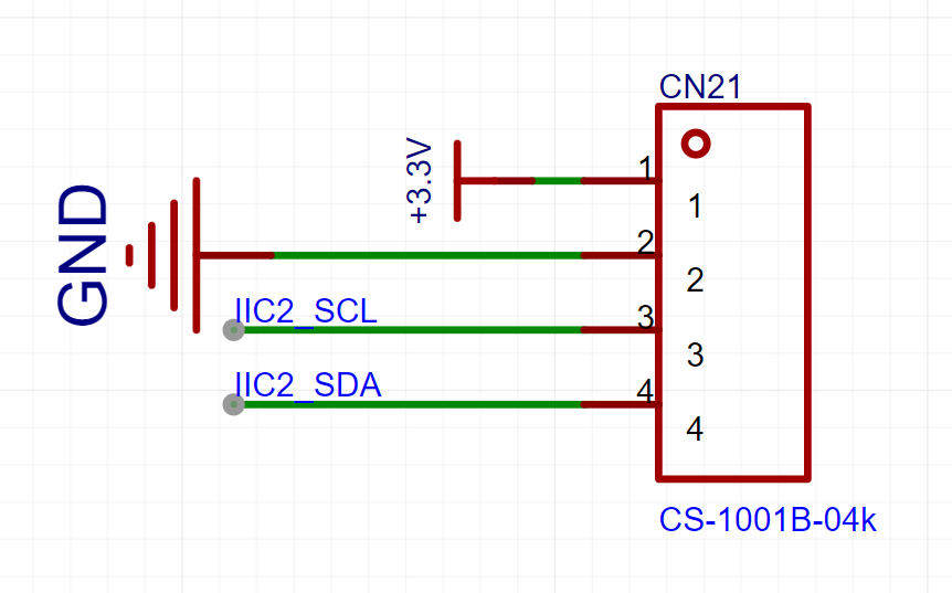
A hardware I/O interface is provided here, which can also be used as a regular GPIO or software I/O. It can be connected to an OLED display, a 24C0X for storage, or other sensors, but the pin order must be considered. It is recommended to use a 4-pin ribbon cable, connecting the pins to the terminals according to the sensor pin order, and then inserting the terminal block into the sensor.
This project includes most common modules and common pinout interfaces. There are no extra pins, but unused serial ports, DACs, ADCs, I/O interfaces, etc., can be used as regular GPIOs.
Soldering sequence...
My soldering sequence is as follows: First, solder the power supply section, using a battery or CNC power supply. Use a multimeter to measure the voltage (5V, 3.3V) to check if it's normal. If not, check if the power chip is facing the wrong direction, if the capacitors and resistors are placed incorrectly, or if the resistor values are wrong. If the voltage is correct, then solder the microcontroller's minimum circuit and reset circuit. You can solder an LED for easier testing. Use a programmer connected to the jumper cap and write an LED blinking test to check if the microcontroller is working properly. If the microcontroller cannot be recognized, you can use the macro mode on your phone's camera (if you have good eyesight, you can look directly) to check for short circuits or cold solder joints on the pins. If the program runs normally, you can continue soldering the gyroscope and magnetometer. These are relatively difficult to solder, so I recommend using a hot air gun or a heating table (the magnetometer is not used much, so you can skip it). Then write an IIC program to test it. If it can read the data, you can confidently solder the rest. Experienced solderers can solder them all in one go. I haven't had time to organize the
program
because I've been busy sending out resumes for an internship. I should have time to organize it if a company hires me.
Model diagram
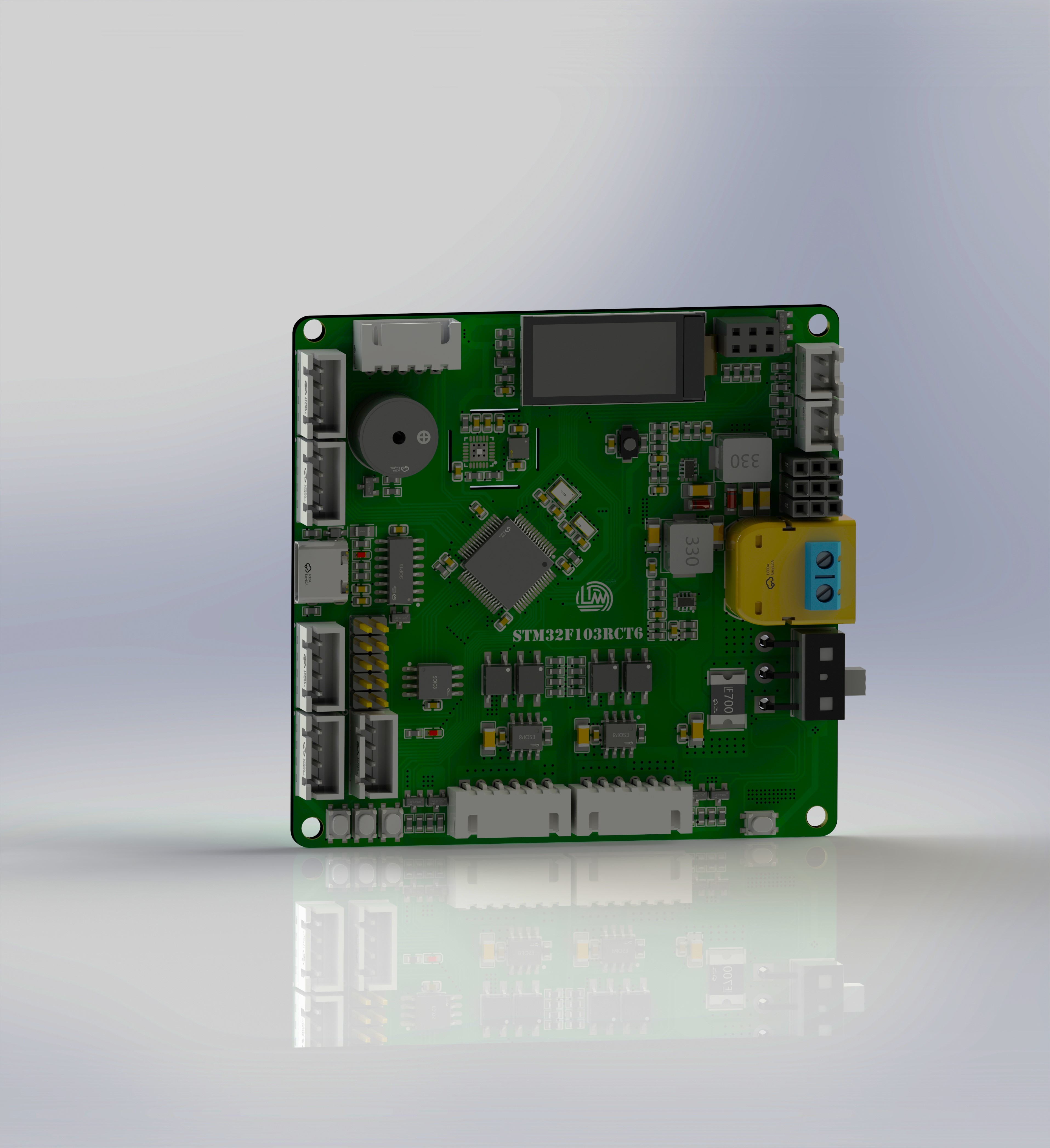
and physical diagram are attached.

Component Reference.rar
PDF_Electronic Design Contest Control Board.zip
Altium_Electronic Design Contest Control Board.zip
PADS_Electronic Design Contest Control Board.zip
BOM_Electronic Design Control Board.xlsx
92258
Liangshan School's curriculum includes a small cart.
This is a sophomore year course project, and also a result of my previous study of the Liangshan School of martial arts. It includes line-following, Bluetooth remote control, automatic following, and obstacle avoidance functions.
Project Overview:
This project is a course design car based on the Liangshan School of LCSC, which includes functions such as Bluetooth tracking and obstacle avoidance.
The system
features two LED lights, one on each side, to simulate the headlight status of a vehicle passing by.
It has two independent buttons, KEYS and KEYM, for starting and switching between driving and driving modes.
A buzzer is included to sound an alarm when encountering obstacles and can also play music by changing its output frequency using a timer.
It is equipped with four motor drivers and four N20 motors, enabling PWM output and speed control.
An HCSR04 ultrasonic module interface circuit is provided, allowing for ultrasonic obstacle avoidance by learning the module's principles and underlying driver code.
An HC-05 Bluetooth module interface circuit is also provided, enabling wireless remote control of the car via a mobile Bluetooth app.
The
power supply circuit uses two 7.4V lithium batteries to power the system, which is then stepped down to 5V by a step-down chip to power the microcontroller. The LCSC Liangshanpai core board connects to the LED lights, button circuits, obstacle avoidance circuits, tracking circuits, Bluetooth remote control circuits (for wireless remote control), buzzer, and motor drive circuits on the smart car expansion board.
Principle Analysis (Hardware Description)
1. The principle of line following is based on detecting black lines: An infrared emitter emits light to the ground. When the infrared light encounters a white surface, it is reflected. The infrared receiver receives the reflected light, and after passing through a Schmitt trigger, it outputs a low level. Therefore, the movement on the black line can be determined by reading the I/O port levels of the left and right line following.
2. The basic principle of ultrasonic following
: An ultrasonic sensor (not a transceiver) is installed at each end of the vehicle, and a person holds an ultrasonic module. The distances from the left and right sides to the person form a triangle.
When the vehicle is facing the person, the distance between the two ultrasonic modules on the vehicle is A=B.
When the person turns left, A is always less than B; similarly, when the person turns right, A is always greater than B.
When the person walks forward, the distance between A and B is always greater than the set distance. We only need to control these distances.
3. The TXD and RXD of the Bluetooth module must be connected to the RXD and TXD of the microcontroller respectively for normal serial communication. Then, the serial port is configured in the software. The switch function is used to process the data received by Bluetooth and execute the corresponding movement.
4. Power Supply Circuit: The power supply is a battery holder that connects two 3.7V lithium batteries to power the vehicle. After the power comes in, it passes through an ME6210A50PG step-down chip. This chip has a maximum input voltage of 18V and can output a fixed 5V voltage to power the microcontroller and peripheral devices. The motor drive chip is directly powered by a 7.4V battery. It also includes a Schottky diode (SS34) to prevent reverse polarity connection of the power input, providing protection. A 100uF capacitor is also added for buffering and filtering.
The assembly instructions
emphasize DIY, so all modules are separated. For specific assembly, refer to the assembly diagram.
Connect the motor and battery box using M3 screws and studs. The stacking method maximizes the vehicle's application without excessively increasing its size, and all modules can be custom-made free of charge.
Software code is attached. Video link:
see attachment.
3d.png
2C7DEE0243D034703AC3360DD99B720E.mp4
DC2E76AED148B0B38811E7A7C91D9BA5.mp4
07A7343061FB44727F76A6C55099EF76.mp4
car.rar
PDF_Liangshan School Course Design Car.zip
Altium_Liangshan School Courseware Car.zip
PADS_Liangshan School Course Design Car.zip
BOM_Liangshan School Course Design Car.xlsx
92259
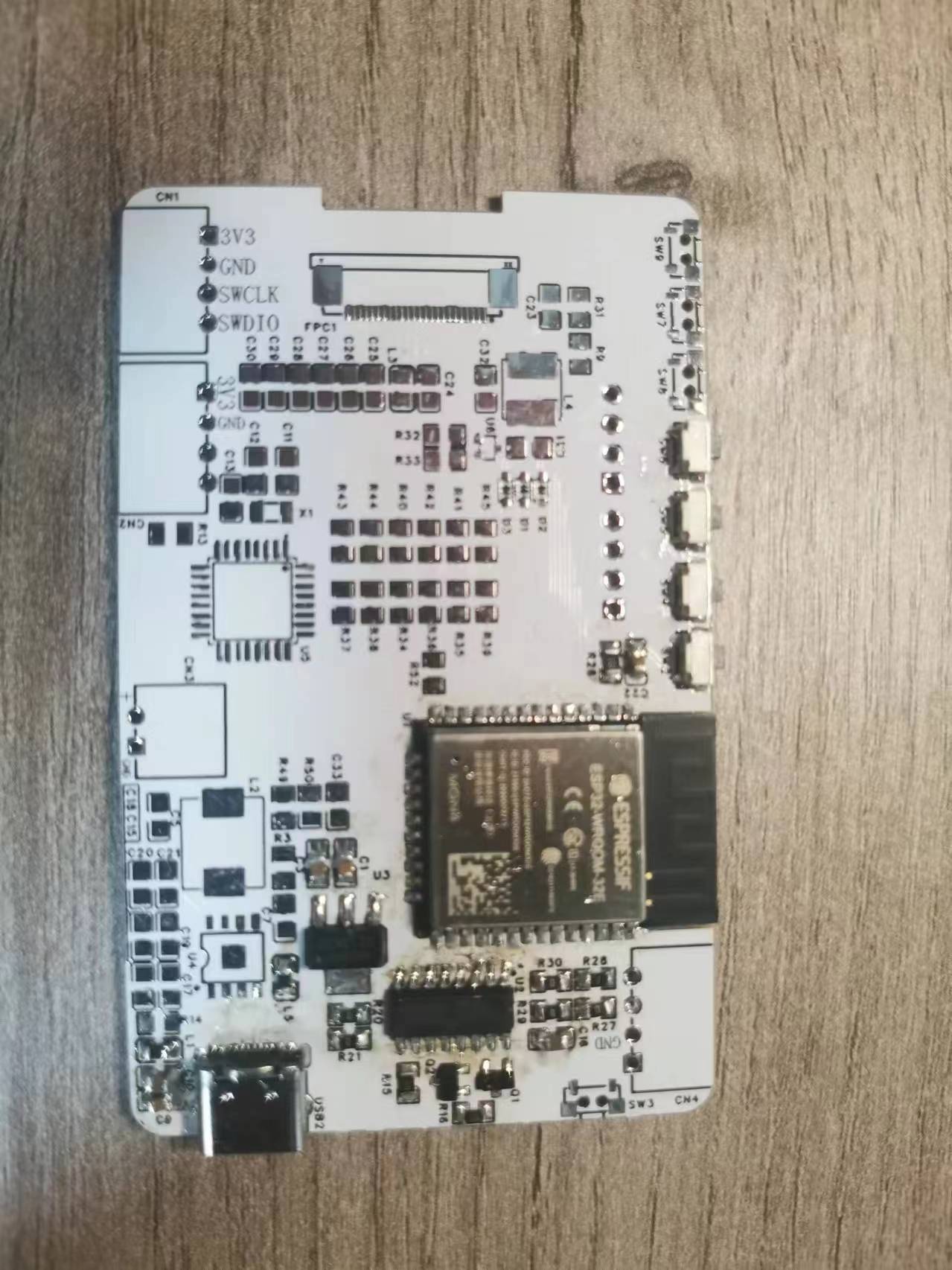
Based on Skystar STM32F407VET6 expansion board
This project is based on an expansion board made from the Skystar STM32F407VET6 Youth Edition and is used for learning development board applications.
The project uses the Skystar STM32F407VET6 to bring out all the pins. This expansion board also adds corresponding peripheral interfaces, such as Bluetooth, OLED screen, and buttons, to facilitate beginners' in-depth understanding of USART, IIC, external interrupts, and other knowledge.
PDF_Based on Skystar STM32F407VET6 Expansion Board.zip
Altium_Based on Skystar STM32F407VET6 Expansion Board.zip
PADS_Based on Skystar STM32F407VET6 Expansion Board.zip
BOM_Based on Skystar STM32F407VET6 Expansion Board.xlsx
92260
electronic
 The back has three LED lights, each controllable via Bluetooth.


 京公网安备 11010802033920号

 291C42A5R624BA


