A solar-powered camping light made with a graffiti-style, zero-code, RGB string light solution will make you the coolest kid on the block this summer!
The story begins with a bottle of candy. My daughter finished the candy and said the bottle was pretty and she didn't want to throw it away. I glanced at it and thought it could be used to make a light! So I kept it, and that was it!
Procrastination got the better of me! Until I saw this issue's theme from JLCPCB—what a coincidence! I was already thinking about making a camping light, and this one fit the theme perfectly! So let's get started!
Main circuit:

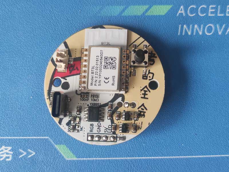
The YX8951 chip can handle both solar and conventional charging, allowing for low-voltage, low-current charging with a maximum charging current of 1A!
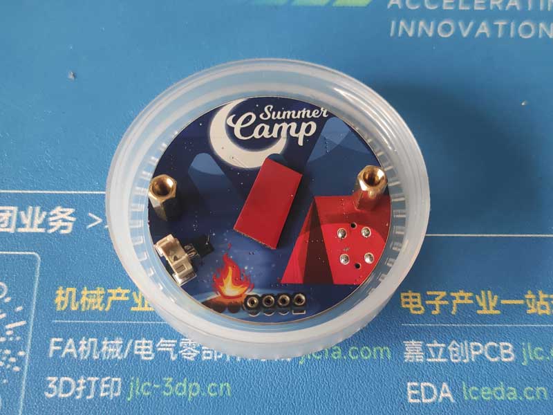
JLCPCB Color Silkscreen PCB:
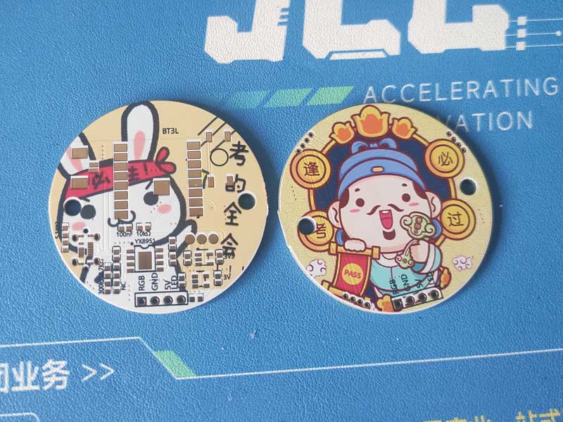

Soldering Completed:

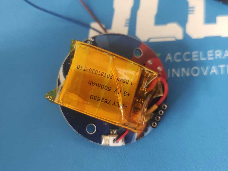
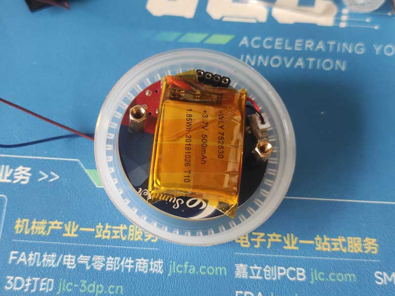
Battery Installed on Back of Upper Board:
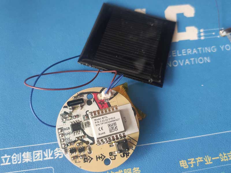
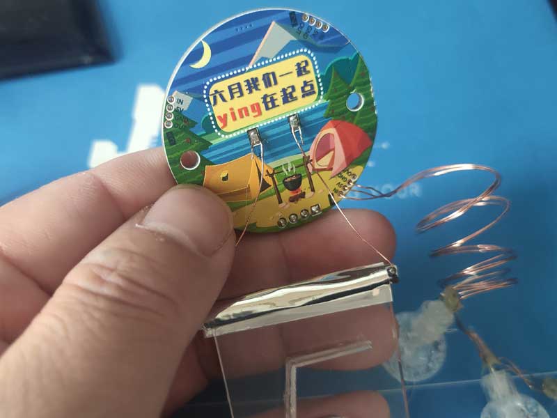
Solar Panel Installed:
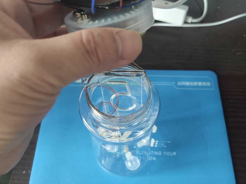
LED Board with Engraved Numbers:

LED Board and Lower Board Use Flexible Interface for Easy Replacement:
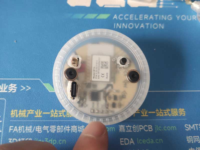
Drill Holes in the Bottle Cap and Connect the Upper Board with M3 Screws:
Screw on M3 Studs and Prepare to Connect the Battery with Double-Sided Tape:
Install Battery:
Screw on Bottle Cap:
Solar Panel and Bottle Cap Use Magnetic Adhesion for Easy Installation and Removal:

Installation Complete:
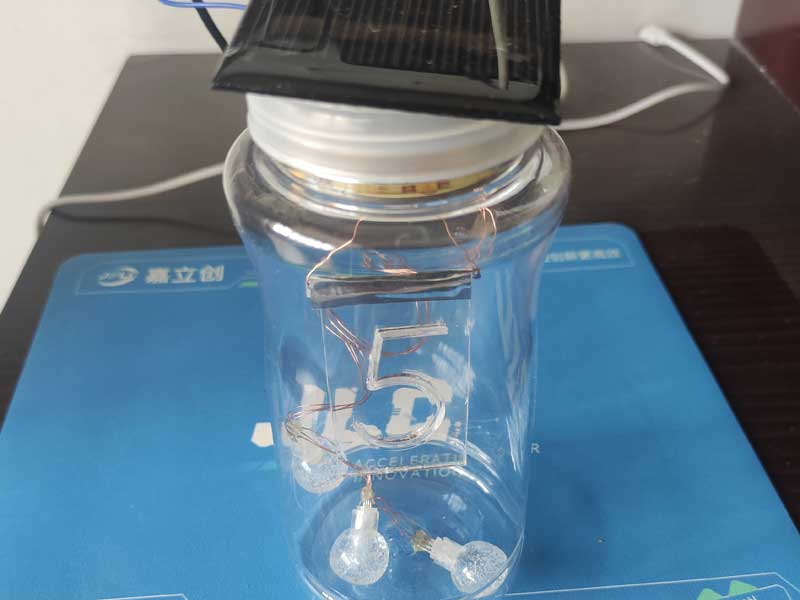
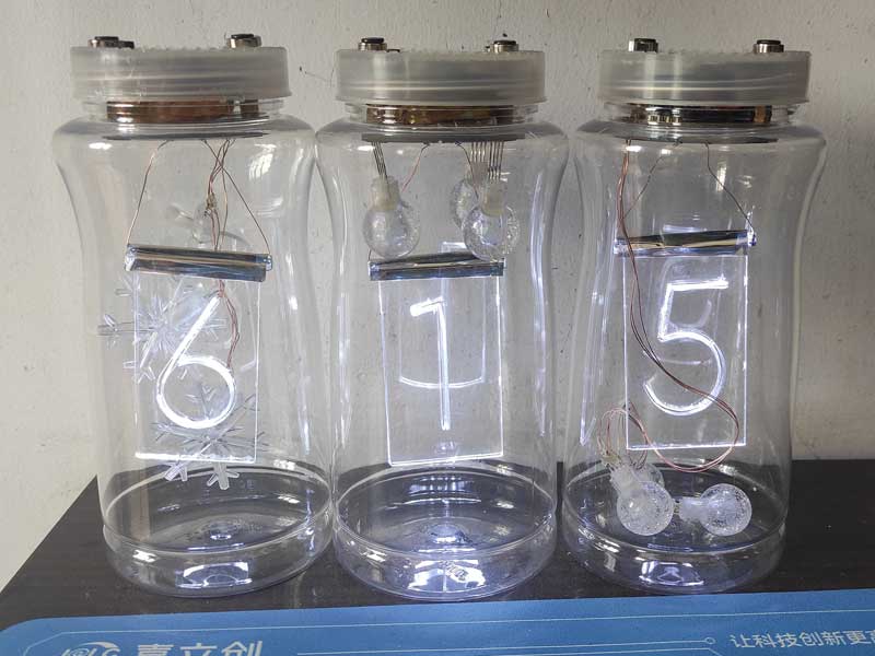
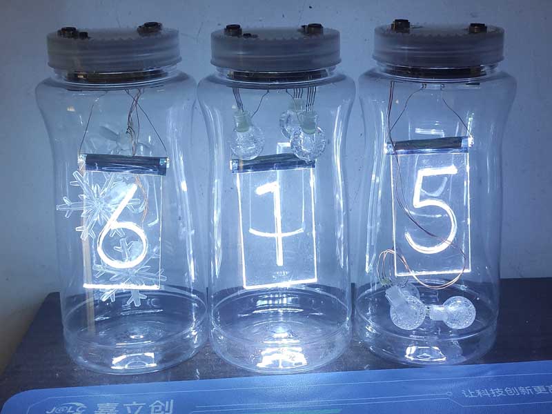
Turn on the Lights:

Illuminate the Number Board:

The number board can be replaced with meaningful numbers or text!
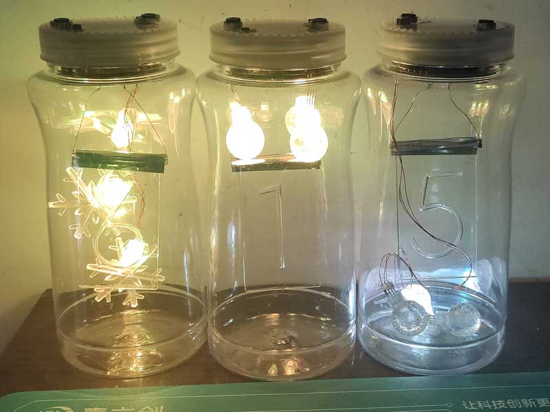
Hang it up:


PDF_Summer Electronic Fun - Solar-Powered Colorful Camping Light.zip
Altium_Summer Electronic Fun - Solar-Powered Colorful Camping Light.zip
PADS_Summer Electronic Fun - Solar-Powered Colorful Camping Light.zip
BOM_Summer Electronic Fun - Solar-Powered Colorful Camping Light.xlsx
91265
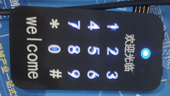
Touch-sensitive combination lock body
Bare-metal control - Touchscreen combination lock:
1. Monitors battery voltage to provide battery level warnings.
2. Enables touch control of virtually anything through touch sensitivity configuration.
3. Allows users to set different password combinations for their own use, others' use, permanent passwords, and temporary passwords.
Project Description:
Touch buttons enable a contactless interaction method, enhancing the user experience.
This improves upon and replaces traditional mechanical buttons, making it a powerful tool for remote controls, smart home devices, and related industrial equipment.
Open Source License:
CC BY_ND 4.0. JLCPCB
's excellent event
supports open source
projects. Related Functions:
Implemented using a microcontroller:
1. Battery level detection;
2. Touch buttons replacing mechanical buttons;
3. DC motor drive;
4. Switching between fixed and temporary passwords.
Project Attributes:
Smart Touch Lock.
First time participating, thanks to JLCPCB for the event.
Project Progress:
Schematic design has begun,
using JLCPCB EDA. The first part, touch password, is complete;
the second part is in progress, adding a card swipe
design. Principle
1: Using the microcontroller's built-in ADC function to collect battery level data
and provide an alarm when the level is below a set threshold (when ADC resolution requirements are not particularly high, the microcontroller's internal 12-bit ADC can be used directly; this project uses the latest STC8h64TL microcontroller).
Principle 2: Touch button implementation
2-1 1. Read the initial touch value and the value after touch.
2.2. Adjust the touch range according to the difference, and adjust the sensitivity according to the actual PCB board design.
3. Drive the DC motor.
3.1. This design uses the dedicated motor driver chip TL118S for easy application and reduced PCB space.
3.2. Use the built-in PWM function of the microcontroller to adjust the speed of the DC motor.
4. Design fixed password and temporary password.
Use the microcontroller's own EEPROM to store the set password. The password will still be preserved after power failure.
The microcontroller's own AD acquisition function collects battery power.
Touch button replaces the original mechanical button (when a finger touches the button, it will change the button's capacitance value. The microcontroller determines whether the button has been touched by detecting the change in capacitance value.)
Touch threshold detection - threshold when there is no touch, threshold after touch, set the corresponding sensitivity according to the difference, and then perform debouncing and interrupt the execution of the corresponding result display
software description
overall framework, first determine the touch button value - monitor the battery power in real time - switch the state according to different functions set
void main(void)
{
P_SW2 |= 0x80;//Enable access to extended register xsfr
IRCDB = 0x10; // Decrease IRCDB setting to increase internal high-speed oscillator debouncing
EA = 1;//Enable global interrupt
EAXSFR();/* Extended register access enabled */
Timer0_Init();
GPIO_config();
UART_config();
ADC_config();
Touch_Init();
while (1)
{
// SetWakeUpTime(50); // Related to lock/unlock time
Touch_Scan();
/**********************************************/
Show_Vol(); // Display battery voltage
/**********************************************/
handle_key_function(); // State machine switching
/**********************************************/
}
}
Touch button part:
void Touch_Init(void)
{
u8 i;
TSRT = 0x00; // No LED time-sharing scan
TSCHEN1 = 0xff;//TK0~TK7
TSCHEN2 = 0x0f;//TK8~TK12 1111
TSCFG1 = (7
TSCFG2 = 2;//Configure the internal reference voltage of the touch button controller (AVCC voltage divider ratio), 0(1/4) 1(1/2) 2(5/8) 3(3/4)
// TSCTRL = (1
TSCTRL =0xa0; //0xa0
//B7:TSGO=1 Enable touch button 1000 0100
//B6:SINGLE=1 Single scan mode, =0 Automatic repeat scan
//B5:TSWAIT=1 After completing one round of scanning, TSIF is set to 1 by hardware. At this time, the touch button controller will pause scanning until TSIF The next round of scanning only begins after the flag is cleared to 0.
//B4:TSWUCS=0 Use internal 32K crystal oscillator
//B3:TSDCEN=0 Disable 16-bit comparator
//B2:TSWUEN=1 Enable low-power wake-up function
//B1B0:TSSAMP=11 Single key scan 4 times
TSWUTC = 50;
IE2 |= 0x80; // Allow touch key interruption
for(i=0; i
{
TK_differ[i] = fazhi[i]; // Set initial difference
TK_lowest[i] = fazhi[i]*3; // Set initial lower limit value, detection lower limit = threshold*3
TK_counter[i] = 0;
Zero_Sub_Cnt[i] = 0;
Zero_Add_Cnt[i] = 0;
}
tpFlag = 0;
JudgeFlag = 0;
read_cnt=0;
TK_TimeOut = 0;
B_Zero_Flag = 1;
ChannelSet = ((u16)TSCHEN2
ScanFreq = 10; //Set the effective touch button continuous detection time
}
This part initializes the touch button settings. Note the wake-up time register TSWUTC, this selection is related to power consumption
. The most important part is the function switching part, which is set using the state machine.
void handle_key_function(void)
Physical demonstration is shown
in the attachment .
Design Notes
1. Setting the touch threshold 2. Setting the touch sensitivity
Other parts
will be added later, such as card swiping, fingerprint, and face authentication. We will continue to learn.
WeChat image_20240528130003.jpg
WeChat_20240528125859.mp4
0525
Panel - Redesign.epanm
Project Links.txt
PDF_Touchscreen combination lock body.zip
Altium Touchscreen Lock Body.zip
PADS_Touchscreen Password Lock Body.zip
91266
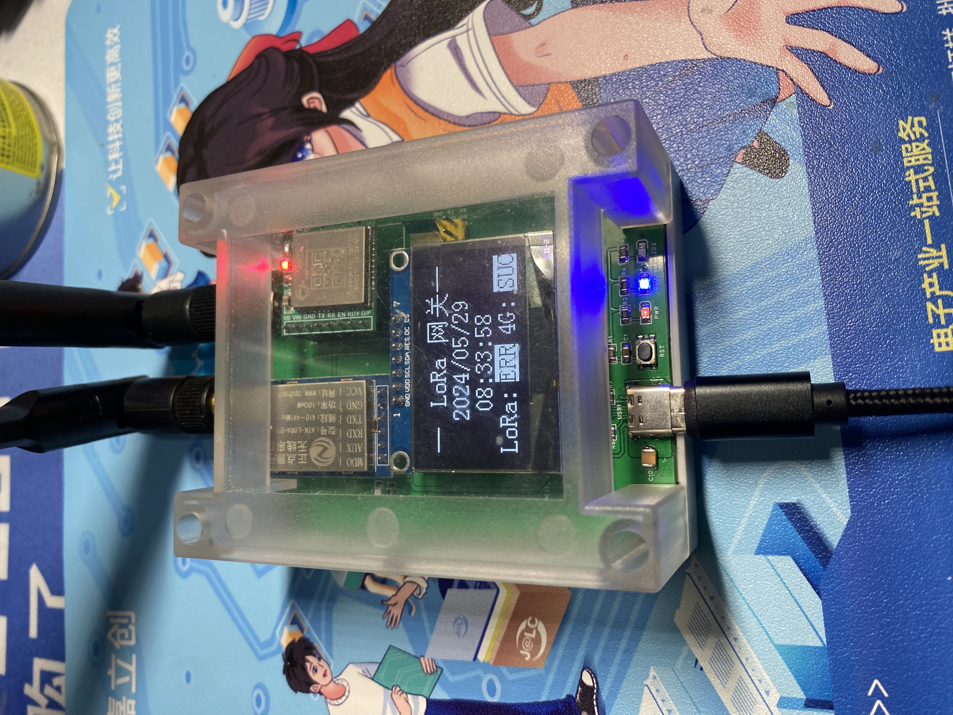
Simple LoRa2Cat.1 Gateway
A simple LoRa2Cat.1 gateway, using serial LoRa and serial Cat.1 4G modules, quickly enables LoRa signal data to be uploaded to the cloud.
The current version 1.0V
documentation has been uploaded as an attachment. Please leave a message at the bottom if you have any questions.
Project Introduction:
This project primarily receives node signals via serial LoRa (ATK-LoRa-01) and forwards the data packets to the FS800E 4G module via an STM32G0 chip, enabling data uploading to the cloud.
It features a 1.3-inch OLED screen displaying the current data status between the node and the cloud, showing the current date and time, and internally using an RTC for timekeeping, allowing for scheduled time updates when necessary.
Three onboard LEDs indicate power, operation, and communication status. A reset button and a debug download interface are also included.
The biggest advantage of this project is that it allows for rapid transmission of node data packets to the cloud with almost no coding required. Its simplicity makes it convenient.

Features:
The serial LoRa module enables data reception and transmission.
The 4G module can be configured via a host computer in various modes, such as TCP, UDP, and MQTT.
The screen displays date parameters and communication status.
It is compatible with industrial control enclosures to protect the screen and communication unit. Instructions for Use:
Configure the LoRa parameters and the MQTT parameters of the 4G module before use.
Plug in the power, wait to acquire the date and time parameters, and set the RTC timekeeping.
Receive LoRa signals and forward them to the 4G module; data packets are transmitted to the cloud via the MQTT protocol.


Physical Demonstration

Precautions
: 1. When soldering, pay attention to the soldering order to ensure the power supply is correct and to avoid burning out subsequent circuits! The soldering order should follow the principle of from shortest to smallest, and from inside to outside.
2. The circuit has been verified. Solder according to the component parameters in the schematic diagram. It is recommended to solder the power supply first, and only solder other peripheral components after confirming that everything is correct.
3. When using board cleaning fluid, be careful not to touch the buttons, as corrosion will make them difficult to use.
4. It is recommended to use the schematic diagram parameters; the BOM may contain errors.
Acknowledgements:
Thank you for your patience in reading. Given my limited technical skills, if there are any omissions or errors, please provide your valuable feedback.
LoRa2Cat.1 data package.zip
PDF_Simple LoRa2Cat.1 Gateway.zip
Altium_Simple LoRa2Cat.1 Gateway.zip
PADS_Simple LoRa2Cat.1 Gateway.zip
BOM_Simple LoRa2Cat.1 Gateway.xlsx
91268
Six-port high-power high-speed USB 3.2 Gen2-HUB
It features five USB 3.2 Gen 2 ports and one USB 2.0 port, with a maximum peak power supply capacity of 5V@20A. Each port has independent overcurrent protection and is independent of the host power supply. It uses the USB7206C solution.
The device features five
USB 3.2 Gen 2 ports (USB-A, backward compatible with USB 2.0), supporting high-power USB devices, but the peak current per port is recommended not to exceed 2.5A, and the rated current not to exceed 2A. It also
includes one USB 2.0 port (USB-A), supporting high-power USB devices, but the peak current per port is recommended not to exceed 2.5A, and the rated current not to exceed 2A.
It uses an XT60 input 12V external power supply. Basic functions require at least 12V@1.5A; when all downstream ports need to run at 5V@2A, at least 12V@6A is required.
It uses a USB-B connector as the upstream interface, connecting to a PC.
[Image of the actual device and

speed test results are included.
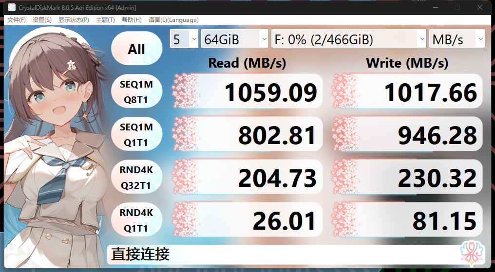
] Usage Notes:
1. This project is designed with a maximum peak external power supply capacity of 20A for all six USB ports. The peak current per port is recommended not to exceed 2.5A, and the rated current not to exceed 2A
. 2. With the increase in external USB devices and the acceleration of actual communication speeds, the U13 will significantly increase its heat generation, requiring a heatsink. The maximum thermal dissipation is approximately 2.0W (for reference only).
3. Discrepancies between the schematic and the actual device are marked with blue marks and dashed boxes. Please carefully check the actual device.
4. D8 and D9 need to be shorted with a small amount of solder after confirming that the 3.3V and 1.15V voltage tests are correct.
5. If you encounter intermittent device recognition failure after powering on, code 43, repeated reconnection, or disk failure after writing to a USB storage device for a period of time: i. Check if the crystal oscillator and crystal oscillator load capacitor are matched; ii. Check if the reset sequence is correct and if it has been handled according to the notes; iii. Check if inferior components, such as capacitors, have been replaced in the 3.3V and 1.15V power supply circuits.
6. It is not recommended to replace certain components with inferior ones, as this may cause performance degradation or unusable devices.
7. This project is open source according to the CC-BY-NC 3.0 license standard. Therefore, you are required to use this project in strict accordance with this license. You may make non-commercial, non-profit adaptations of this project as needed, but you must retain the attribution to the original work.
Complete System BOM
Name
Quantity
Remarks
Motherboard
1
Front Panel
1
Rear Panel
1
Case (100mm)
1
https://item.taobao.com/item.htm?_u=q2cq2ak20ebd&id=527187308231&spm=a1z09.2.0.0.33382e8dEwW94N
Heatsink
1
Any size, 12mm x 12mm or larger, can be purchased.
PDF_Six-Port High-Power High-Speed USB 3.2 Gen2-HUB.zip
Altium Six-Port High-Power High-Speed USB 3.2 Gen2-HUB.zip
PADS_Six-Port High-Power High-Speed USB 3.2 Gen2-HUB.zip
BOM_Six-Port High-Power High-Speed USB 3.2 Gen2-HUB.xlsx
91269
electronic


 京公网安备 11010802033920号

 DE2B3KX102KB3A


