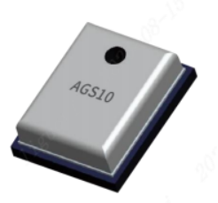
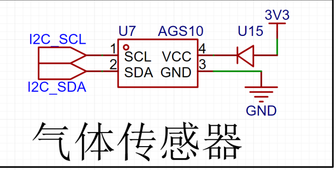
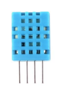
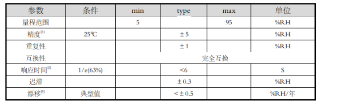
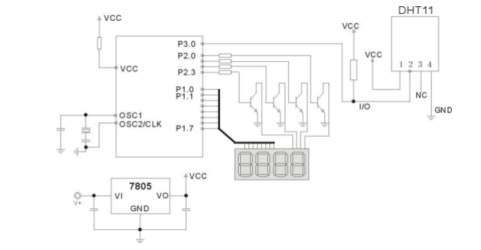
 uses the standard IIC communication protocol, making it compatible with various devices. The IIC physical interface includes two interfaces: a serial data signal (SDA) and a serial clock signal (SCL). During design, both interfaces need to be pulled up to VDD through resistors ranging from 1kΩ to 10kΩ. The sensor operates at 3V, while our voltage range is only 5V and 3.3V. A Schottky diode can be connected in series at the sensor's VCC pin. The voltage drop of a typical diode is between 0.6V and 1.7V, while that of a Schottky diode is typically between 0.15V and 0.45V. 3.2 Harmful Gas Sensor Design: The DHT11 digital temperature and humidity sensor is a composite temperature and humidity sensor with a calibrated digital signal output. It utilizes dedicated digital module acquisition technology and temperature and humidity sensing technology to ensure high reliability and excellent long-term stability. The sensor includes a capacitive humidity sensing element and an NTC temperature sensing element. Applications include HVAC, dehumidifiers, agriculture, cold chain storage, testing and inspection equipment, consumer goods, automobiles, automatic control, data loggers, weather stations, home appliances, humidity regulators, medical devices, and other related humidity detection and control. Advantages include low cost, long-term stability, relative humidity and temperature measurement, excellent quality, ultra-fast response, strong anti-interference capability, ultra-long signal transmission distance, digital signal output, and precise calibration. Pin descriptions: VDD: 3.3~5.5V DC power supply ; DATA: Serial data, single bus ; NC: Unused pin; GND: Ground, negative power supply. Product parameters: 1. Relative humidity ; 2. Temperature; 3. Electrical characteristics . Typical circuit: Serial communication description (single-wire bidirectional) . Single bus description: The DHT11 device uses simplified single-bus communication. A single bus means there is only one data line; data exchange and control in the system are all completed by the single bus. Devices (master or slave) are connected to the data line via an open-drain or tri-state port, allowing the device to release the bus when not transmitting data, thus enabling other devices to use the bus. A single bus typically requires an external pull-up resistor of approximately 4.7kΩ, so that the bus is in a high-level state when idle. Because they are master-slave junctions, the slave can only respond when the master calls it. Therefore, master access to devices must strictly adhere to the single-bus sequence; if the sequence is disordered, the device will not respond to the master. Application circuit diagram 3.3 Noise sensor introduction: Using a microphone to detect sound and thus noise. Advantages: An electret microphone is a sound-to-electrical conversion device that converts sound signals into electrical signals. Its characteristics include small size, light weight, simple structure, wide frequency response, high sensitivity, vibration resistance, and low price, making it widely used in electronic devices such as recorders, wireless microphones, and voice-activated switches. Product parameters and application circuit design: The output voltage of a microphone typically ranges from a few millivolts to several hundred millivolts, depending on factors such as the sound pressure level of the sound source, the pickup distance, and the microphone's sensitivity. Generally, the microphone's output voltage is 5–10 mV. While a single-chip microcomputer may not be able to detect it initially, with the addition of a suitable amplification circuit, it can be detected by the microcontroller. This enables the implementation of a simple noise sensor.


 For specific procedures, please refer to the video by Teacher Eva on Bilibili: https://b23.tv/ueGo1L7 (Other videos are also very helpful!!!).
All reference designs on this site are sourced from major semiconductor manufacturers or collected online for learning and research. The copyright belongs to the semiconductor manufacturer or the original author. If you believe that the reference design of this site infringes upon your relevant rights and interests, please send us a rights notice. As a neutral platform service provider, we will take measures to delete the relevant content in accordance with relevant laws after receiving the relevant notice from the rights holder. Please send relevant notifications to email: bbs_service@eeworld.com.cn.
It is your responsibility to test the circuit yourself and determine its suitability for you. EEWorld will not be liable for direct, indirect, special, incidental, consequential or punitive damages arising from any cause or anything connected to any reference design used.
Supported by EEWorld Datasheet
EEWorld
subscription
account

EEWorld
service
account

Automotive
development
community

Robot
development
community

About Us Customer Service Contact Information Datasheet Sitemap LatestNews


Room 1530, 15th Floor, Building B,
No.18 Zhongguancun Street,
Haidian District,
Beijing, Postal Code: 100190
China
Telephone: 008610 8235 0740
 京公网安备 11010802033920号

 JR25WRC-10P


