RemoteIO - A Simple Modbus Remote I/O Board

Update Log
20240501:
PCB version upgraded to V1.1.
Fixed the error where ADS1115's VDD was not correctly connected to the 5V power supply. (Many thanks to [shaoele] for pointing out the power connection error).
Power supply section comments aligned.
Avoided inductor bottom-level windings.
Optimized DCDC chip FB feedback circuit.
Added analog input program to the microcontroller program, released version V40501.
The firmware in the attachment has also been updated to 40501.
Before we begin:
1. The design referenced some open-source projects on the open-source forum and borrowed some circuit designs; thanks to the open-source experts.
2. The current version of the I/O board has been prototyped. Except for the software function of the analog input section, all other functions have been verified and have run without communication problems for 4 consecutive days.
3. The hardware, program, and debugging software are all open source; everyone is welcome to refer to them. If you plan to apply this to a project, please conduct some anti-interference and aging tests yourself and bear the risks arising from its use.
4. The next version plans to address the analog input issue and design a PCF8575 expansion I/O board.
Design Background:
I currently work in automation equipment development, primarily dealing with PLCs, host computers, and robotic arms. I've found that in certain special situations or when space is limited, using PCBs and microcontrollers is more convenient for implementing functions. Therefore, in my spare time, I've been studying electronic circuits. To solidify my knowledge and avoid failing in practice despite initial understanding, I spent some time creating this I/O board. Through the hardware and software design of this I/O board, I aim to reinforce my learning. Of course, due to insufficient knowledge and limited ability, there may be design flaws or oversights. I would be very grateful for any guidance from experts.
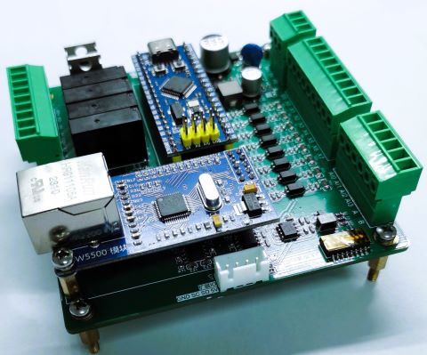
Module Description:
Function Introduction:
A Modbus remote I/O board based on the STM32F103C8T6 microcontroller, suitable for host computer communication, remote control, and other scenarios.
Main control chip: STM32F103C8T6 microcontroller
; Power supply: DC24V;
Inputs: 8-channel isolated digital inputs; Outputs
: 6-channel isolated digital outputs
; Analog inputs: 4-channel 16-bit analog inputs;
Communication interfaces: RS485, Ethernet, TTL serial port, IIC
communication; Parameter settings: Station number, baud rate, and 120-ohm terminating resistor can be set via DIP switches;
Operating indicators: One ERR indicator and one RUN indicator;
Communication protocols: Modbus RTU, Modbus TCP;
Development environment: Visual Studio Code;
Development framework: PlatformIO + Arduino;
Software architecture: FreeRTOS + watchdog
timer; Open source program: HEX program file is included in the attachment; the program needs to be downloaded to the microcontroller;
Debugging software: Debugging tools are included in the attachment; need to be connected to the module via RS485 or network; External interfaces
use pluggable terminals for easy and quick wiring.
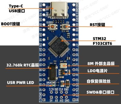
Main control chip: STM32F103C8T6 minimum development board.
Using the YD-STM32F103C8T6 microcontroller with a Type-C interface, the build quality and performance are excellent, and I personally feel it offers great value for money.
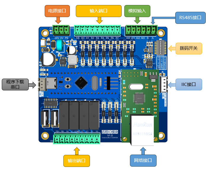
Let's look at the module's
power supply: designed for DC 24V, but tested to work normally from 9-24V.
24V is positive, 0V is negative, and PE is ground.
Inputs: 8 isolated digital inputs.
Bidirectional optocouplers are used for isolation.
SS is the common terminal, X0-X7 are input ports, compatible with NPN/PNP inputs.
Designed to operate at DC 24V, but tested to work normally from 9-26V.
The inputs include a filtering algorithm with a default 5ms response time.
Analog inputs: Uses the ADS1115 chip.
IIC is used to read data from the ADS1115 analog chip.
A voltage follower is used to increase input impedance.
4 inputs, 16-bit ADC accuracy.
Input voltage range 0-5V.
Outputs: 6 isolated digital outputs
, isolated by optocouplers.
PD+ and PD- are the output power supplies; due to the use of a 24V relay, a DC 24V power supply is required.
2 NPN outputs, connected to PD- during output.
4 relay outputs, COM is the common terminal, shared by Y2/Y3/Y4/Y5. Although the maximum current per relay is 3A, the total COM current should not exceed 3A.
Communication interfaces: RS485, Ethernet, TTL serial port, IIC.
RS485 x1: Supports Modbus RTU protocol.
TTL serial port x1: Used for downloading programs or printing information.
IIC interface x1: For future expansion.
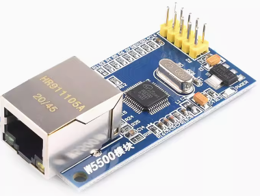
Ethernet x1: Supports Modbus TCP protocol. Ethernet communication is implemented through the W5500 module. Note the module pin orientation adjustment (this module is not needed if only Modbus RTU is required).
Note: The module pin orientation needs to be changed to downwards.
Note: The module pin orientation needs to be changed to downwards.
Note: The module pin orientation needs to be changed to downwards.
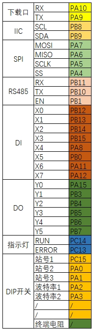
The following diagram
shows

the communication parameters of this module: The station number, baud rate, and 120-ohm terminating resistor can be set and turned on/off via DIP switches.
Station Number Setting: The station number is set using the combination of SW1, SW2, and SW3.
See Table 1 for details. Baud Rate Setting: The baud rate is set using the combination of SW4 and SW5.
See Table 2 for details. Termination Resistor: SW8 is ON when the termination resistor is connected, and OFF when the termination resistor is disconnected. See Table 3 for details.
Table 1
| Station Number | SW3 | SW2 | SW1 |
| --- | --- | --- | --- | | 1
| OFF | OFF
| OFF |
| 1 | OFF | OFF | ON | | 2 | OFF | ON | OFF |
| 3 | OFF | ON | ON |
| 4 | ON | OFF | OFF |
| 5 | ON | OFF | ON | |
6 | ON | ON | OFF |
| 7 | ON | ON | ON |
Table 2
| Baud Rate | SW5 | SW4 |
| --- | --- | --- | |
115200 | OFF | OFF |
| 9600 | OFF | ON |
| 19200 | ON | OFF |
| 38400 | ON | ON |
Table 3
| Termination Resistor | SW8 |
| --- | --- |
| Connect | ON |
| Disconnect | OFF |
Operating Indicators: One ERROR indicator, one running indicator.
ERR Indicator: When the watchdog timeout occurs on the IO board, the ERR indicator remains constant.
RUN Indicator: When the IO board starts scanning input and output, the RUN indicator flashes at 1-second intervals.
Communication Protocols: Modbus RTU, Modbus TCP.
Modbus RTU: Standard Modbus RTU protocol; only the holding register area is used in the program, a total of 20 holding registers.
Default parameters: Station number 1, baud rate 115200 8N1,
ModbusTCP: Standard ModbusRTU protocol, data area is consistent with ModbusRTU.
Default IP: 192.168.1.168
Port: 502
Register address description: See the attached Modbus register description for details.
Development environment: Visual Studio Code, the younger brother of the world's most powerful IDE, Visual Studio.
Development framework: PlatformIO + Arduino
PlatformIO: Integrates many tools and is very easy to use.
Arduino: Simple and easy to use.
Program architecture: FreeRTOS + watchdog timer. A reserved IIC interface
is provided on the board with a 5V power supply, which can be used to further expand more input/output ports. Pin definitions.
Program software section.
Jump to the microcontroller program open source address .
Jump to the debugging tool software open source address.
PCB program download.
Program file: HEX file included in the attachment.
Stlink download: It is recommended to use the Stlink downloader, which costs around ten yuan on Taobao. Only 3 wires are needed, no mode switching is required, convenient and fast. To download via STLink
serial port: you will need a USB to serial adapter. The board has a pre-reserved download port. When downloading, you need to set Boot0 to 1, and then switch Boot0 back to 0 after downloading.
Modbus Register Description
Modbus Address
Parameter Definition
Default Value
Unit
Range
Read/Write
Description
0
Firmware Version Number
40408
/
R
Firmware version number, one digit of the last digit of the year + two digits of the month + two digits of the day
1
Current Station Number
1
/
R
All off bits are 1, other bits are combined, a restart is required after modification DIP3 DIP2 DIP1000:1001:1010:2 and so on, the maximum is 111:7
2
Current Baud Rate
0
bps
R
All off bits 115200, a restart is required after modification DIP5 DIP400:11520001:960010:1920011:38400
3
Parameter Saving
0
/
R / W
After writing the corresponding value, the program will automatically clear it = 10, // Save the value of the Modbus register to EEPROM = 20, // Load the value of the Modbus register from EEPROM = 30, // Restart the device = 66, // Restore factory settings and restart the device
4
Input Filtering Time
5
ms
1-100
R/W
Input port filtering time
5
MAC address bytes 1 and 2
0XCDAB
/
R/W
Automatically generated with microcontroller ID during initialization
6
MAC address bytes 3 and 4
0X12EF
/
R/W
7
MAC address bytes 5 and 6
0X5634
/
R/W
8
Lower 16 bits of IP address
0X01A8
/
R/W
For example: 192.168.1.168, a restart is required after modifying the IP address for it to take effect. 15: High byte 01=1, low byte A8=168 16: High byte C0=192, low byte A8=168
9
Higher 16 bits of IP address
0XC0A8
/
R/W
10
Device running time
in seconds
0-65535
R
Device running time, repeats 0-65535, can be used for heartbeat detection
11
Input status feedback
R
bit0-bit7 correspond to X0-X7 respectively
12
Output status feedback
R/W
Bits 0-5 correspond to Y0-Y5 respectively
. 13.
Extended Input Status Feedback
R:
Bits 0-7 correspond to X10-X17 respectively. Bits 8-15 correspond to X20-X27 respectively
. 14.
Extended Output Status Feedback
R/W:
Bits 0-7 correspond to Y10-Y17 respectively. Bits 8-15 correspond to Y20-Y27 respectively
. 15.
AI0 Analog Voltage Input
R:
The analog voltage input of AI0 is converted to a digital value. The voltage input range is 0-5V, and the accuracy is 0.01V. The digital value is converted using the formula (measured value 0.0001818) to obtain the actual input voltage value. For example, if the digital value is 27415, then the input voltage is 274150.0001818 = 4.98V. Note: If the read value is 32767, it indicates that the analog input chip section has not been fully initialized and there is a fault.
16.
AI1 Analog Voltage Input
R
Calculation (Refer to AI0)
17.
AI2 Analog Voltage Input
R
Calculation (Refer to AI0)
18.
AI3 Analog Voltage Input
R
Calculation (Refer to AI0)
The wiring

test section
uses ModbusPoll software
. Test software: Modbus software I used.
Link: https://pan.baidu.com/s/1gVSAOsch675w53tLc9f6kw?pwd=um7m Extraction code: um7m Copy this content and open the Baidu Cloud mobile app for easier operation.
Hardware wiring: Connect the IO board power supply; you can connect the output or input side power supply as needed.
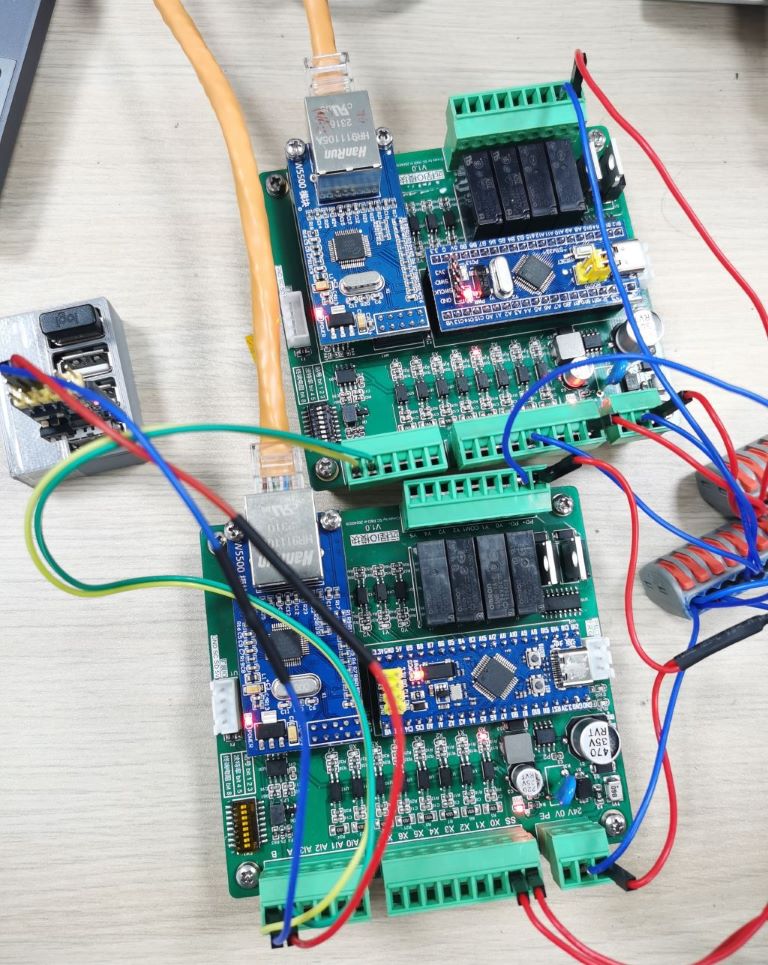
Software: Used ModbusRTU and ModbusTCP to connect to the IO board simultaneously .

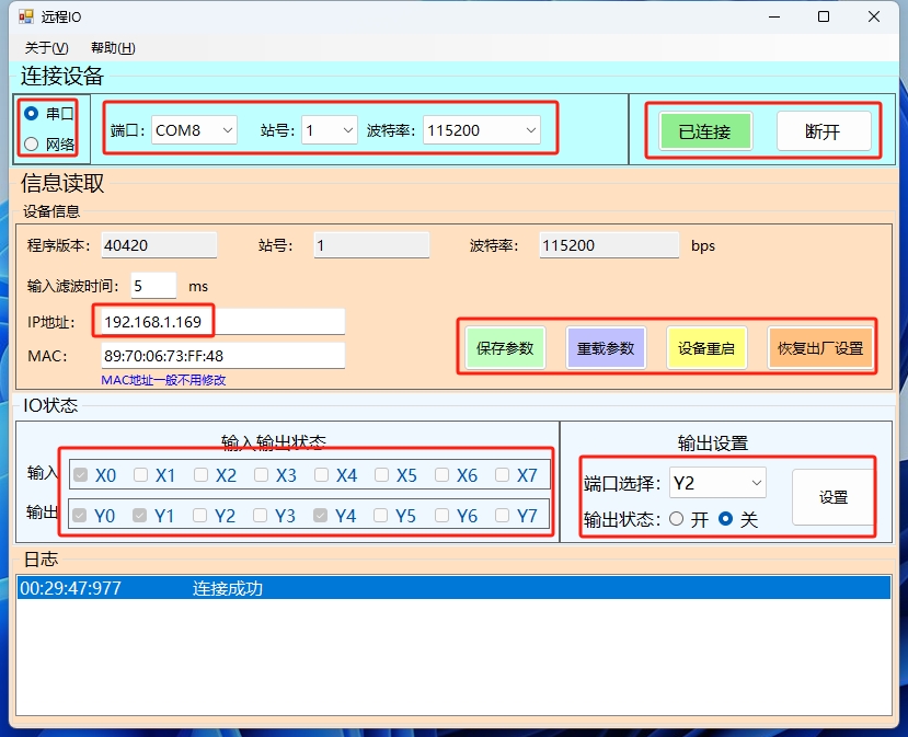
For example, you need to set the IP address to 192.168.10.5.
Connecting the IO board: Connect to the IO board via ModbusRTU or ModbusTCP.
IP address to hexadecimal conversion: You can use a computer calculator to calculate the hexadecimal value, which is C0.A8.0A,05.
Set IP: Set address 9 to 0xC0A8 and address 8 to 0x0A05.
Save parameters: Set address 3 to 10.
Restart: Set address 3 to 30.
Configuration complete, the IP address of the IO board has been modified. The debugging tool
software is included in the attachment;
please refer to the help section for usage instructions. Three types of pluggable terminal blocks
need to be added manually and are not listed in the BOM: 1*6P: Part number: C7247, quantity 1; 1*3P: Part number: C8413, quantity 1; 1*9P: Part number: C31287, quantity 2. Regarding some issues: Using the STM32 minimum development board: It allows for quick verification of your ideas and reduces the difficulty of replication for those who want to learn. Using the W5500 module: Considering that Ethernet is not needed in some situations, this module can be omitted. Note that the module's pins are pointing upwards by default; you need to change the pins to pointing downwards, which may be a bit troublesome. Analog Input Section: To improve resolution and input impedance, the analog voltage is divided by resistors before entering a voltage follower circuit made of an operational amplifier. The op-amp output then enters the input of the ADS1115. Therefore, the conversion formula is (input value 4.096/32767) 1.4545. Finally, I would like to thank the open-source software and hardware experts on the internet again, allowing us to stand on their shoulders and do something meaningful.


 京公网安备 11010802033920号

 1KS269-85GG


