
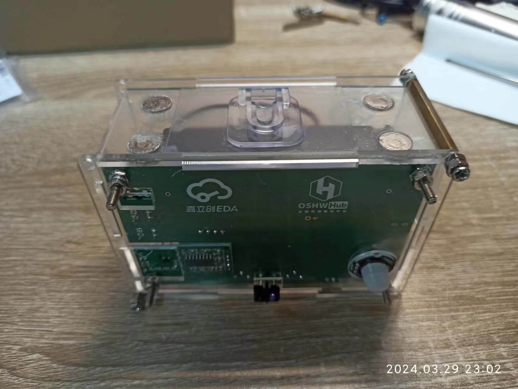

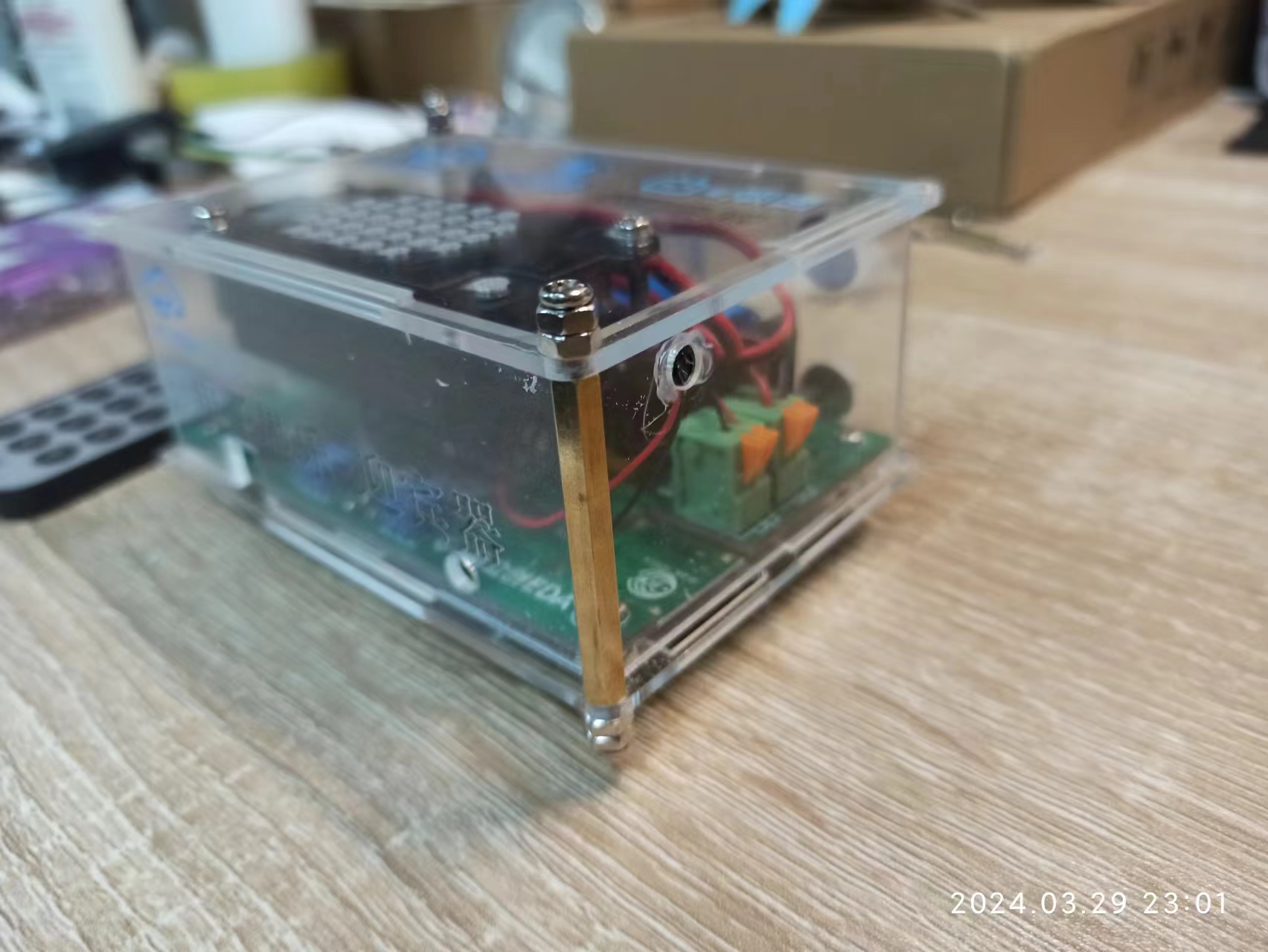

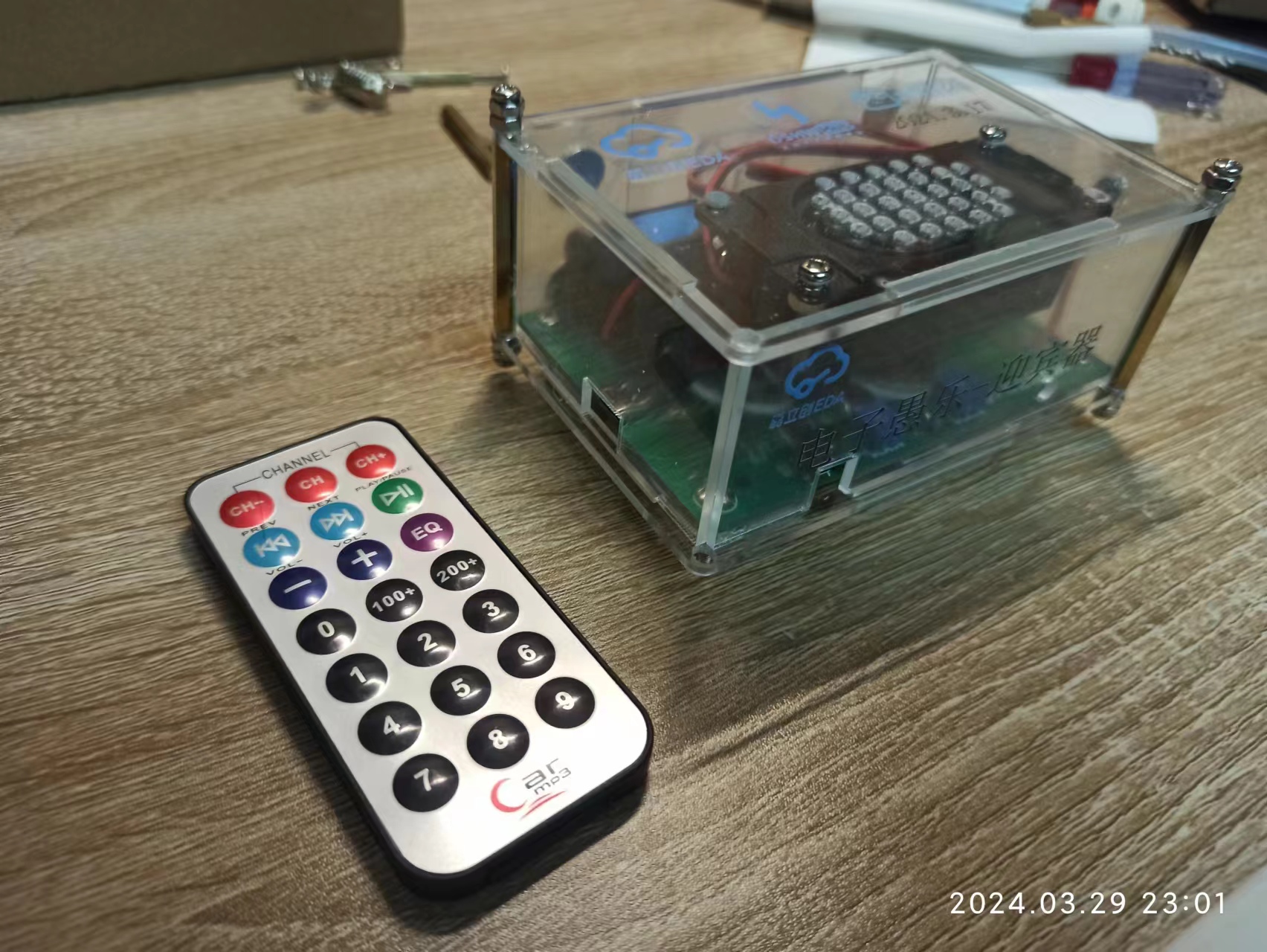
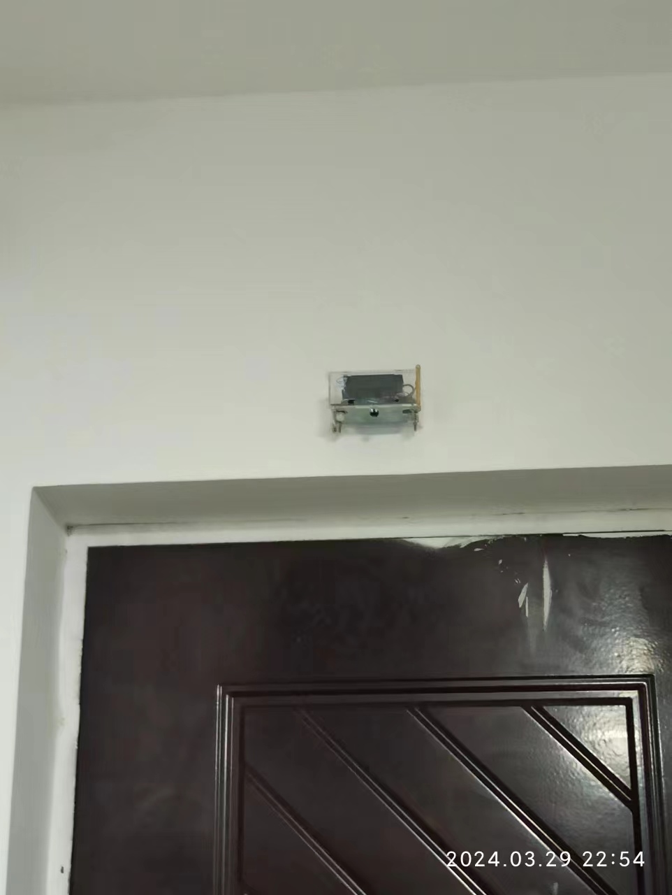
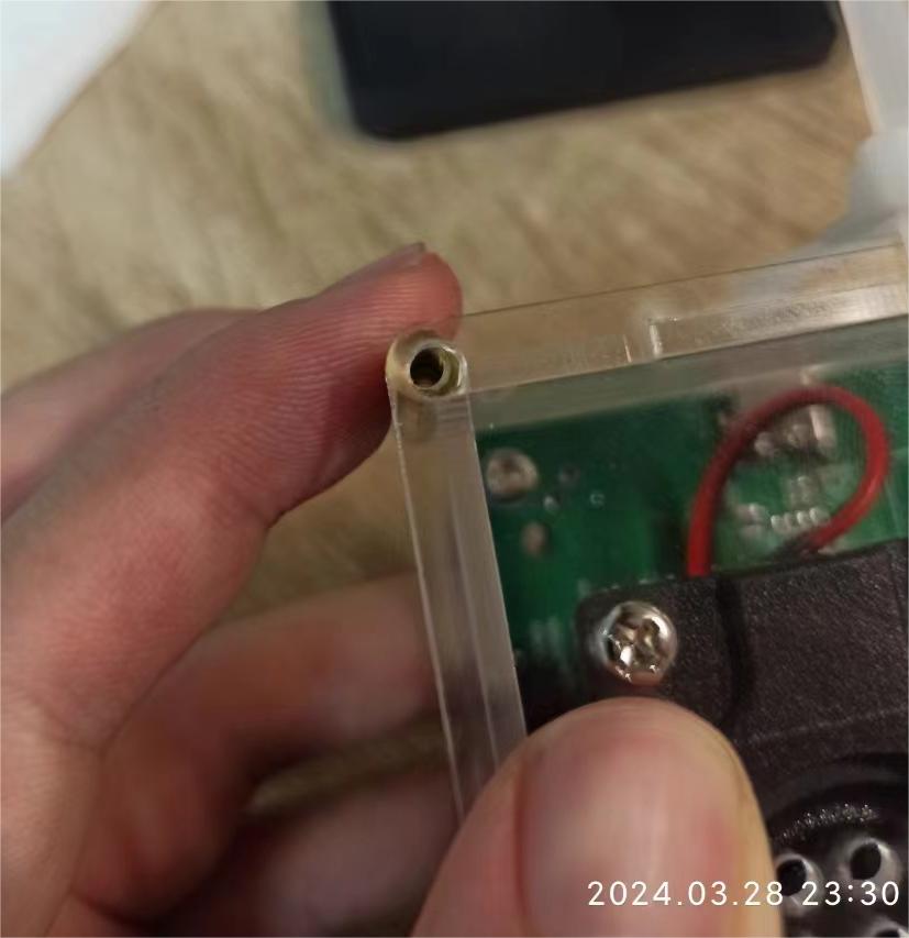
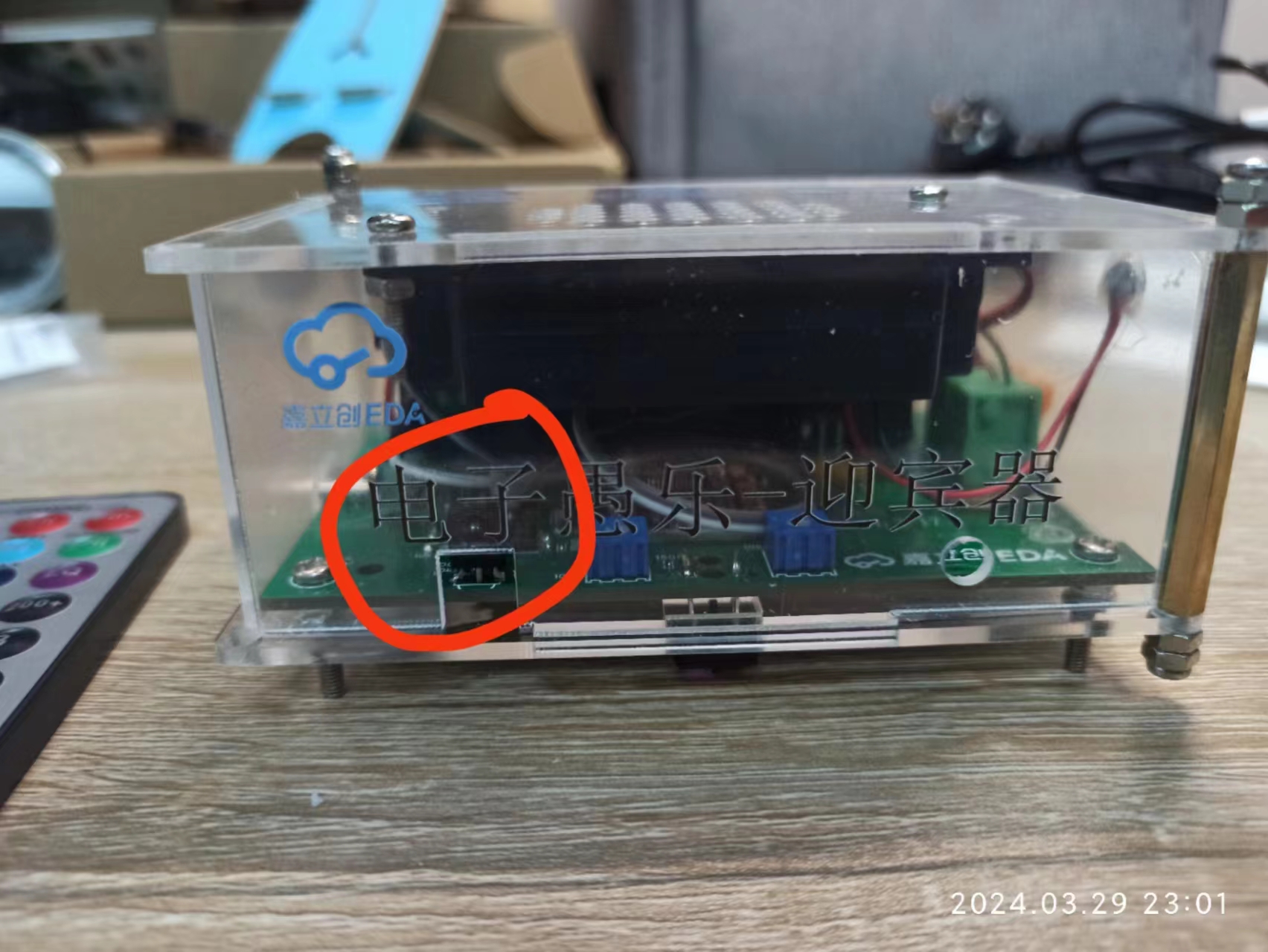
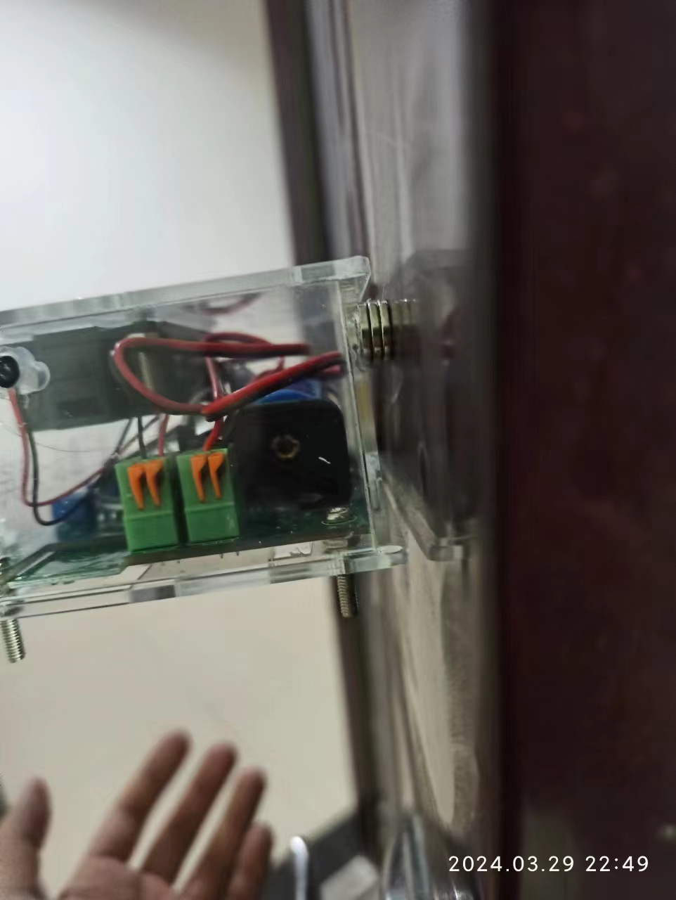
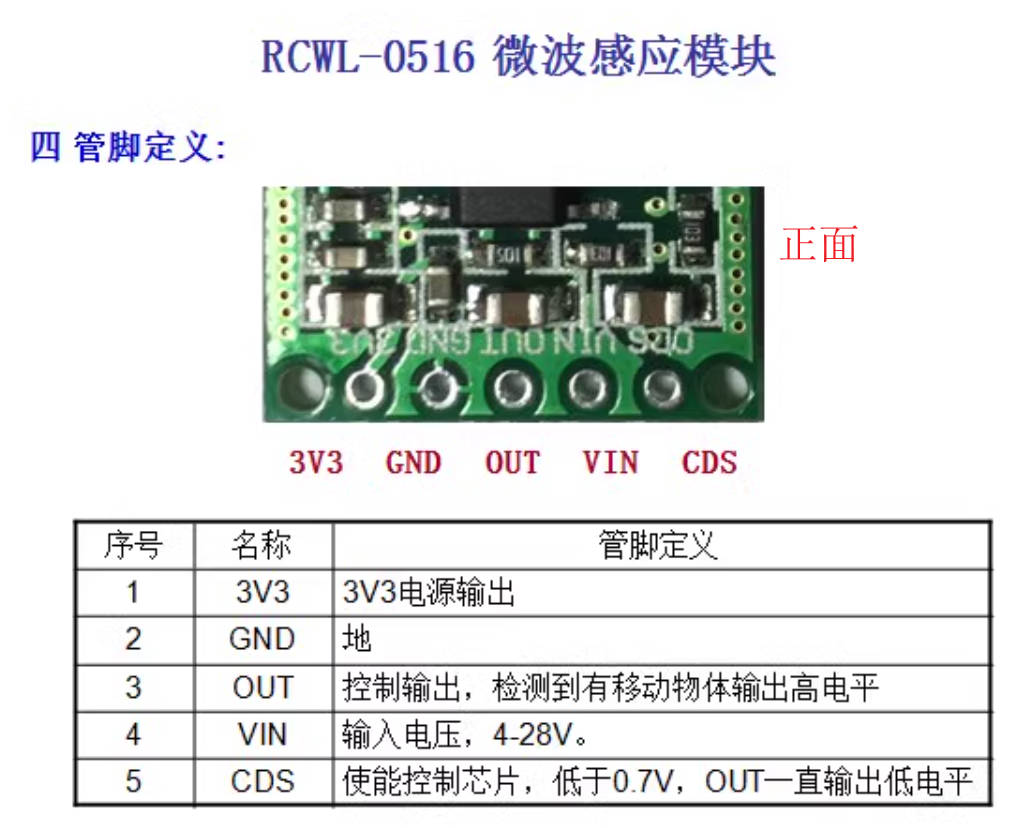
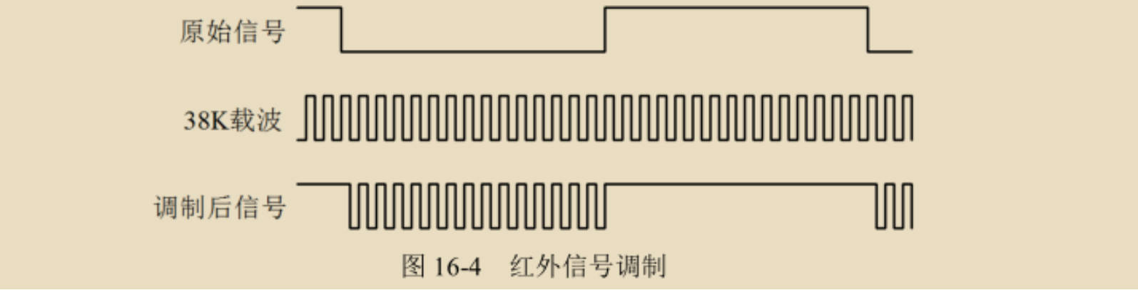
 . The power circuit, controlled by a TPS5400, cannot charge while the battery is running. The specific reason is unclear. After installing the lithium battery, I tried to charge it using the Type-C interface, but the board started smoking when I plugged and unplugged the Type-C power cable twice. Later, it was discovered that the ASRPRO core board was damaged, with a short circuit between the 3V3 and power supplies to ground. I spent ten yuan to buy a new ASRPRO core board, which delayed things by a week. Later, I switched to a lithium battery and a UPS power supply. The reflective photoelectric switch, pin U9, was placed in the upper right corner of the PCB and was blocked by a screw post, preventing it from detecting whether someone was downloading programs. The pin should be moved to the edge of the PCB and brought out through a hole in the casing. After assembling the casing, the program download will not use the CH340. When downloading programs to ASRPRO, it's often necessary to disconnect the GND of the USB-to-TTL module from the board's GND. A normally closed microswitch could be designed to briefly disconnect the GND connection during download. ~~ This was my first time designing a panel, and oh, there were a few mistakes. Later, I saw a tutorial from JLCPCB on Bilibili (【Panel Design | JLCPCB EDA Professional Edition Introductory Tutorial (17)】 https://www.bilibili.com/video/BV1h84y1f72t/?share_source=copy_web&vd_source=0a637a1f0e78b552a2c48ced1367c40f). If I had watched the tutorial earlier, I would have made fewer mistakes. 1. The screw holes on the outer perimeter used to connect the upper and lower panels were not positioned correctly, and a copper pillar could not be placed. They were later modified using a hand drill. 2. The position and size of the opening for the infrared receiver were not suitable. 3. It was unnecessary to make the opening for the magnet in the back panel recessed, because the protruding parts of the upper and lower panels would increase the contact distance between the magnet and the door frame, resulting in a weakening of the magnetic force. It was necessary to use multiple magnets to attract the magnet to the door. In actual testing, it was possible to attract the magnet to the door using two points, but it was unstable. Four points should be more reliable. Because the dormitory door frame was too small, it was later fixed to the wall using adhesive hooks. The infrared pyroelectric power supply voltage is 3.3V-15V, with a quiescent current of 20uA. It uses a miniature infrared pyroelectric sensor SR602, with a maximum sensing distance of 5 meters. The sensitivity and the duration of the high-level output after successful detection can be adjusted by modifying the resistor. The default high-level duration is 2.5 seconds, and the lockout time is 2 seconds, which is not adjustable. Note: A high-level output will be performed once after power-on, and the high-level duration increases with the delay time. It is said that the human body sensing module should be sealed in a box, the lens should be exposed, and the circuit board should not be exposed. This needs to be considered when designing the casing. The sensing effect is poor when the human body is stationary; it needs to move to generate a temperature difference for detection. The reference circuit for output to the MCU provides a resistor connected in series in the output circuit. This design references that diagram and adds a 10k resistor. The RCWL 0516 microwave radar human body induction switch has a power supply voltage of 4V~28V, an operating current of 3mA, and an operating frequency of 2.7GHz. It can also output 3V3@100mA power. Compared to traditional infrared PIR, this sensor has penetrating detection capabilities, able to penetrate glass and thin wood panels. The side with the components is the front, and its sensing range is better than the other side. The infrared and HS0038BD power supply voltage is 2.5V-5.5V, frequency: 38 kHz. It can receive infrared signals at a frequency of 38kHz with a period of approximately 26µs. It can also amplify, detect, and shape the signal to obtain a TTL level encoded signal and is compatible with CMOS circuits. See: https://www.cnblogs.com/chengo/p/12759808.html It uses the NEC protocol, characterized by: 1. 8-bit address and 8-bit instruction length; 2. Address and command are transmitted twice (ensuring reliability); 3. PWM pulse position modulation, using the duty cycle of the transmitted infrared carrier to represent "0" and "1" . 4. Carrier frequency: 38kHz . 5. Bit duration: 1.125ms or 2.25ms. NEC code bit definition: One pulse corresponds to a 560µs continuous carrier wave. A logic 1 transmission requires 2.25ms (560µs pulse + 1680µs low level), and a logic 0 transmission requires 1.125ms (560µs pulse + 560µs low level). The NEC remote control command data format is: Synchronization code, Address code, Address inverse code, Control code, Control inverse code. The Synchronization code consists of a 9ms low level and a 4.5ms high level. The Address code, Address inverse code, Control code, and Control inverse code are all 8-bit data formats. They are sent in the order of least significant bit first, most significant bit last. The inverse code is used to increase transmission reliability. The TCRT5000 infrared reflective photoelectric sensor uses ASR PRO infrared diodes PA2~PA6 and PB5~6, which are 5V tolerant. PA2, PB5, and PB6 are pull-down pins by default (D), while PA4, PB5, and PC4 are pull-up pins by default (U). PA0 is XIN by default, serving as the clock output interface, and PA1 is XOUT, which is the default output pin. This pin's default function is the clock interface, and its use is not recommended. What are the requirements for the microphone and speaker that come with the ASRPRO sensor? Solution: It is recommended to use a microphone with a sensitivity of -32±3dB and a signal-to-noise ratio ≥65dB, and a speaker with a cavity. You can contact Taobao customer service to purchase these. The recommended speaker is 8 ohms 2W, with a maximum of 4 ohms 3W. It seems that voice output is only possible during wake-up.


All reference designs on this site are sourced from major semiconductor manufacturers or collected online for learning and research. The copyright belongs to the semiconductor manufacturer or the original author. If you believe that the reference design of this site infringes upon your relevant rights and interests, please send us a rights notice. As a neutral platform service provider, we will take measures to delete the relevant content in accordance with relevant laws after receiving the relevant notice from the rights holder. Please send relevant notifications to email: bbs_service@eeworld.com.cn.
It is your responsibility to test the circuit yourself and determine its suitability for you. EEWorld will not be liable for direct, indirect, special, incidental, consequential or punitive damages arising from any cause or anything connected to any reference design used.
Supported by EEWorld Datasheet
EEWorld
subscription
account

EEWorld
service
account

Automotive
development
community

Robot
development
community

About Us Customer Service Contact Information Datasheet Sitemap LatestNews


Room 1530, 15th Floor, Building B,
No.18 Zhongguancun Street,
Haidian District,
Beijing, Postal Code: 100190
China
Telephone: 008610 8235 0740
 京公网安备 11010802033920号

 WH4A-5B-1


