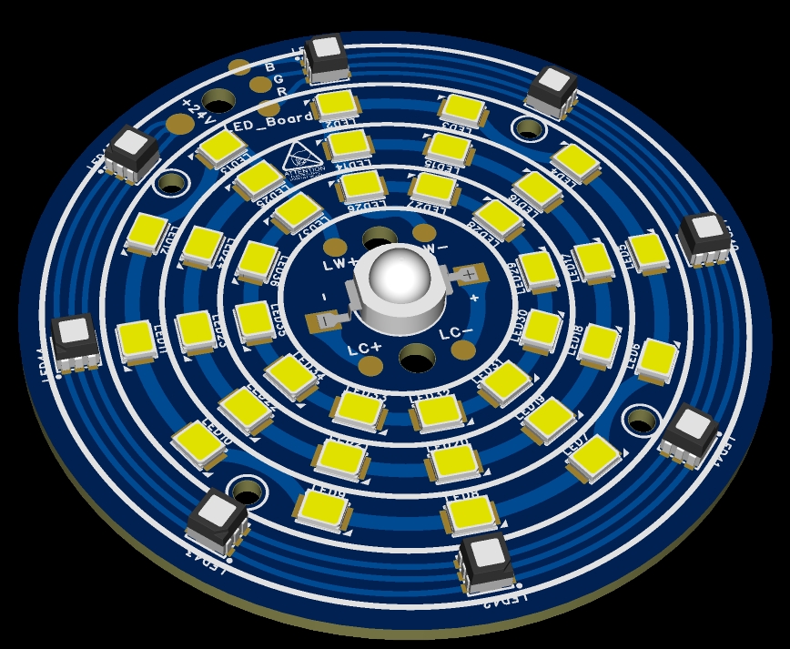
 ; 2. Color silkscreen image of the LED control board PCB;
  3. Actual photo.
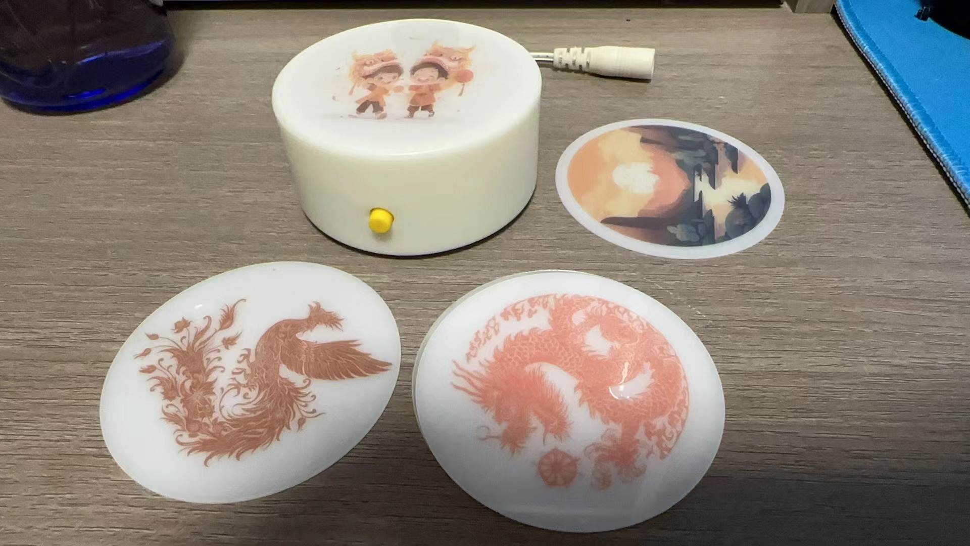
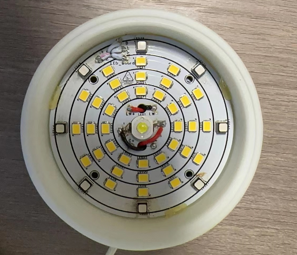
 IV. Circuit description and usage introduction: 1. This project consists of an LED board and an LED control board. The LED board is made of aluminum substrate for easy heat dissipation of the LED beads. The board has 8 3535 RGB LED beads; 1 0.5W high-power LED bead (3.2V cold light LED bead); and 12 warm white 2835 LED beads in series and 3 in parallel, totaling 36 beads.
  3. The project's warm light uses the SY7301 chip, an LED constant current driver chip. The SY7301A features a boost DC/DC converter to provide precise constant current for driving the LEDs. Operating at a fixed switching frequency of 1MHz, it allows the use of small-value external ceramic capacitors and inductors. The series-connected LEDs are driven by a regulated current set by an external resistor. The SY7301A is ideal for driving up to 10 white LEDs in series or up to 40V. Therefore, 12 series-3 parallel 3.2V warm light LEDs were used.
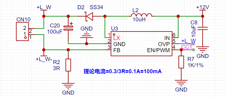
 5. The board also has a reserved power supply module, which uses an existing AC-DC module with a 12V output to power the lamp. An external power supply module is also possible; the board has a reserved 12V power supply pad for soldering out an external DC power supply. Due to space constraints caused by a design flaw in the casing, an external power supply was used in this project. Note that this is the first time designing a casing structure, there are some minor structural issues, but these are acceptable and not 100% perfect, and do not affect usability.
  7. The lamp's top cover uses an acrylic cover plate, also printed by JLCPCB. Below are the acrylic printing specifications. The printed pattern is also included in the PCB project file and is open-source on the project platform. Note that the acrylic in the file does not have adhesive backing because I used acrylic glue. If you need to make it with adhesive backing, you can follow the instructions. Note that the file does not include a cutout for adhesive backing; the file needs to be modified before production.
  V. Product testing video
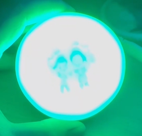

All reference designs on this site are sourced from major semiconductor manufacturers or collected online for learning and research. The copyright belongs to the semiconductor manufacturer or the original author. If you believe that the reference design of this site infringes upon your relevant rights and interests, please send us a rights notice. As a neutral platform service provider, we will take measures to delete the relevant content in accordance with relevant laws after receiving the relevant notice from the rights holder. Please send relevant notifications to email: bbs_service@eeworld.com.cn.
It is your responsibility to test the circuit yourself and determine its suitability for you. EEWorld will not be liable for direct, indirect, special, incidental, consequential or punitive damages arising from any cause or anything connected to any reference design used.
Supported by EEWorld Datasheet
EEWorld
subscription
account

EEWorld
service
account

Automotive
development
community

Robot
development
community

About Us Customer Service Contact Information Datasheet Sitemap LatestNews


Room 1530, 15th Floor, Building B,
No.18 Zhongguancun Street,
Haidian District,
Beijing, Postal Code: 100190
China
Telephone: 008610 8235 0740
 京公网安备 11010802033920号

 171-009-6CS-6K1-18-PB


