 Welding power board
 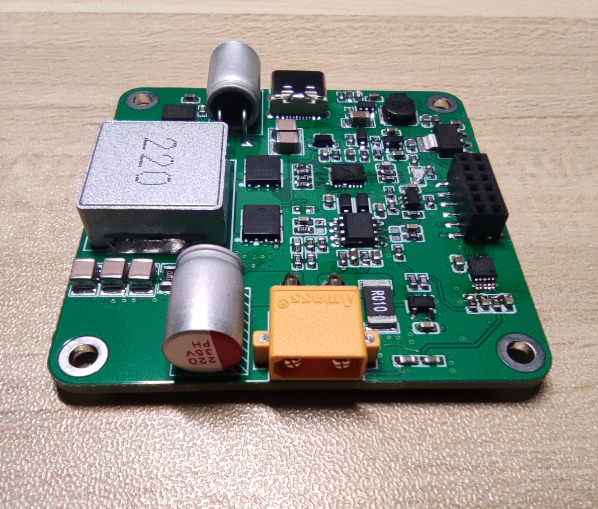 from another angle.
 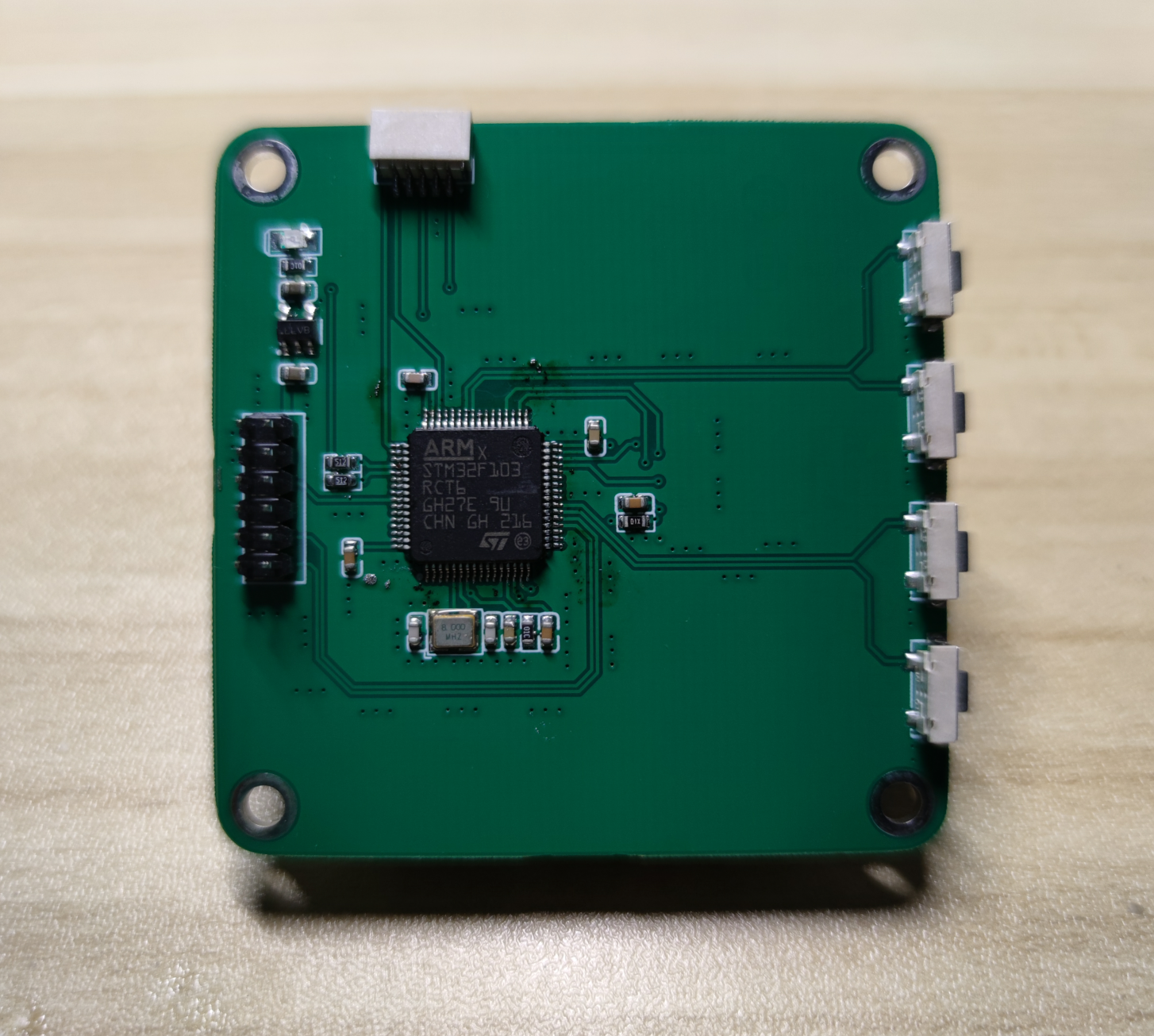 Welding control board (back).
 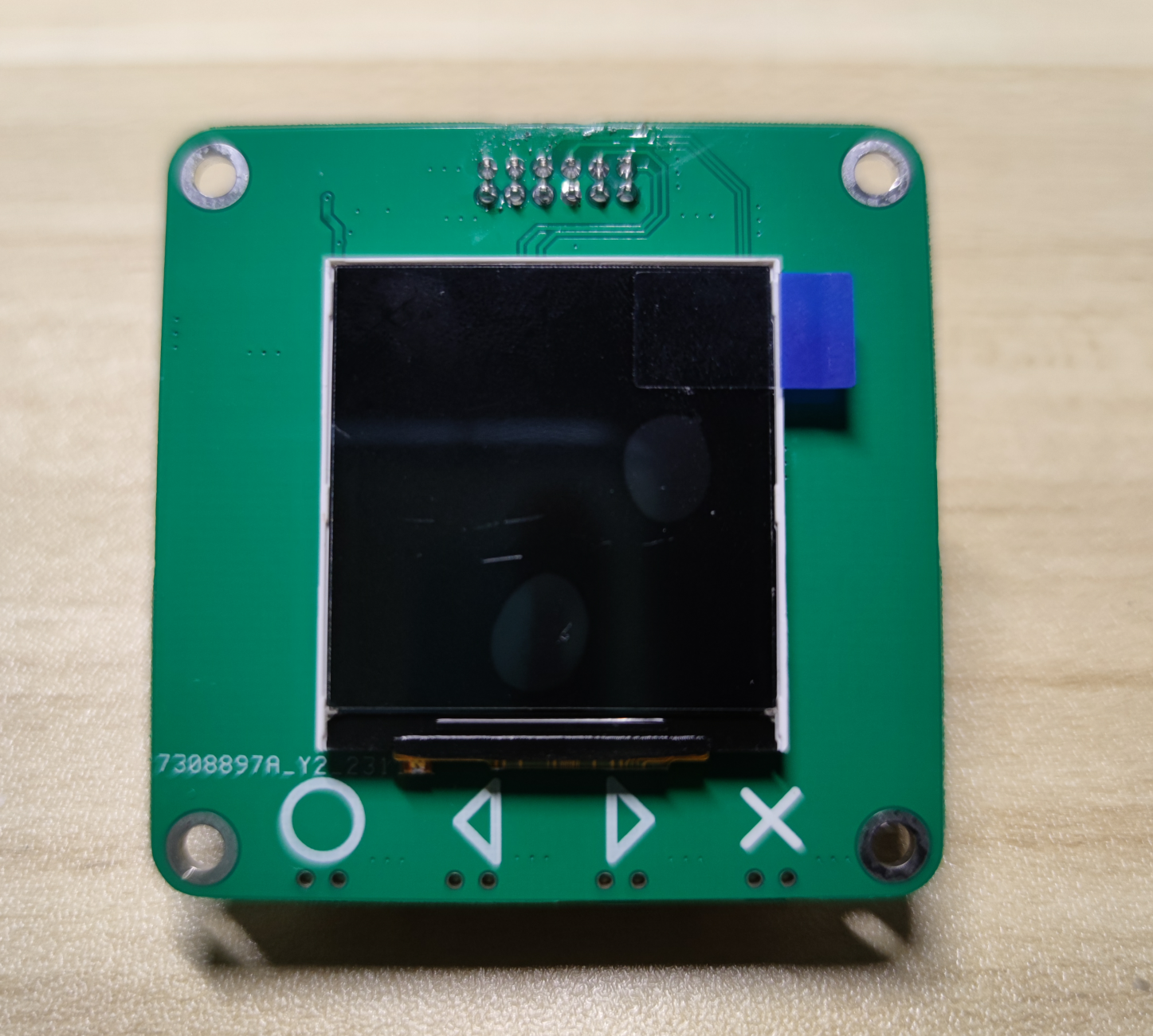 Welding control board (front).
  Originally, it was planned to use 10mm copper pillars for support, but it was found that the connector distance between the power board and the control board was insufficient, so only 8mm copper pillars could be used. If 8mm copper pillars are used, it will cause structural interference between the micro switch and the inductor. The inductor needs to be moved a certain distance to provide support for the micro switch. The button provides some space.
  Screws are made of M3*5mm and 8mm double-through copper pillars.
 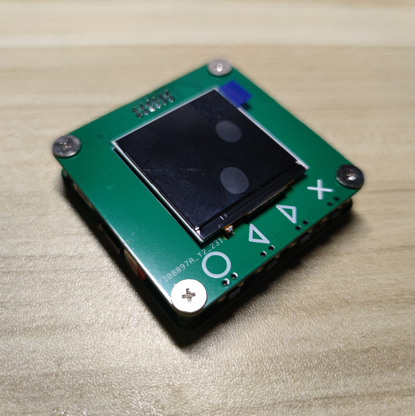 The finished product is shown from
  another angle .
 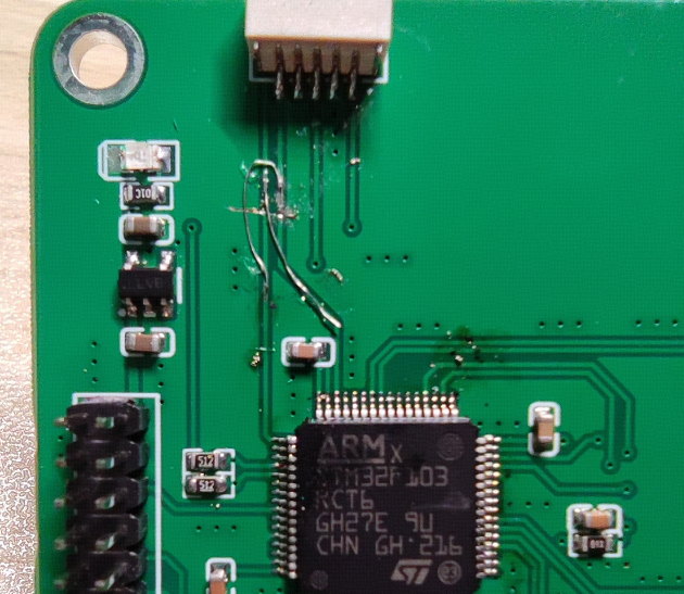 Due to a design error in the schematic, SWDIO and SWCLK were reversed, causing the program to fail to download. Cross-wiring is required for SWDIO and SWCLK.
  During power board debugging, the chip was found to be malfunctioning, with no waveform at the SW node and MOSFET gate. Checking the schematic revealed that pins 17 and 19 were incorrectly connected, preventing the bootstrap capacitor from charging, thus preventing the chip from working properly.
 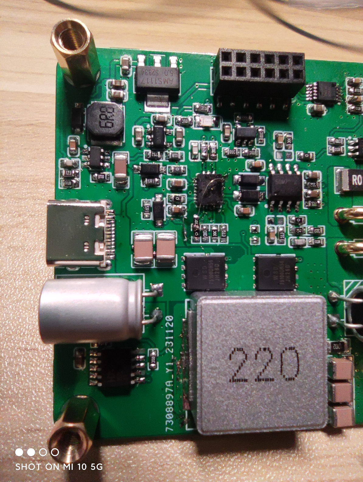 Cross-wiring was performed at pins 17 and 19. Another issue is that the chip needs to operate in FPWM mode. This was not considered in the schematic design and requires manual wiring to change it. A 20K resistor is connected in series from pin 8 to the +10V power supply.
  Software Still under testing. The UI is shown above and shouldn't have major changes. Originally, hardware SPI was planned for screen refresh, but problems arose with this screen; the screen frequently failed to display for unknown reasons (although the program was running normally). Later, software-simulated SPI was used, which allowed the screen to display correctly, but the speed was much slower than hardware SPI, significantly impacting the entire debugging process. The
 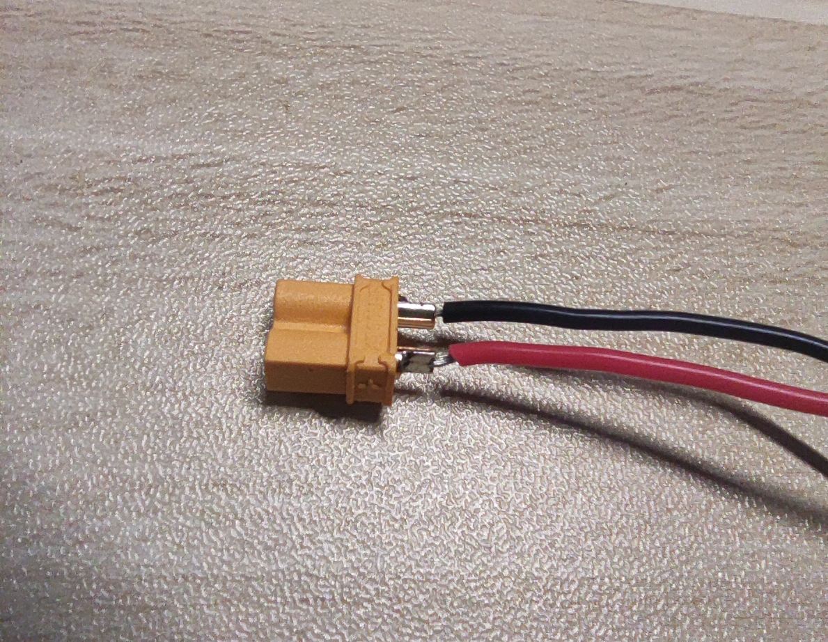 output interface uses an XT30 male connector, but the positive and negative terminals were reversed during schematic design. This means that when soldering the female connector to the male, the positive and negative markings on the casing cannot be followed; they must be reversed.
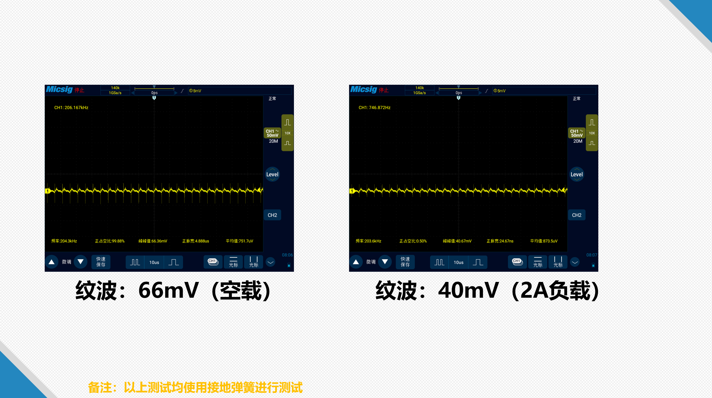 The module output ripple is shown in the image above. Under 5V output, the no-load ripple is slightly higher than under load, exceeding 1%.
 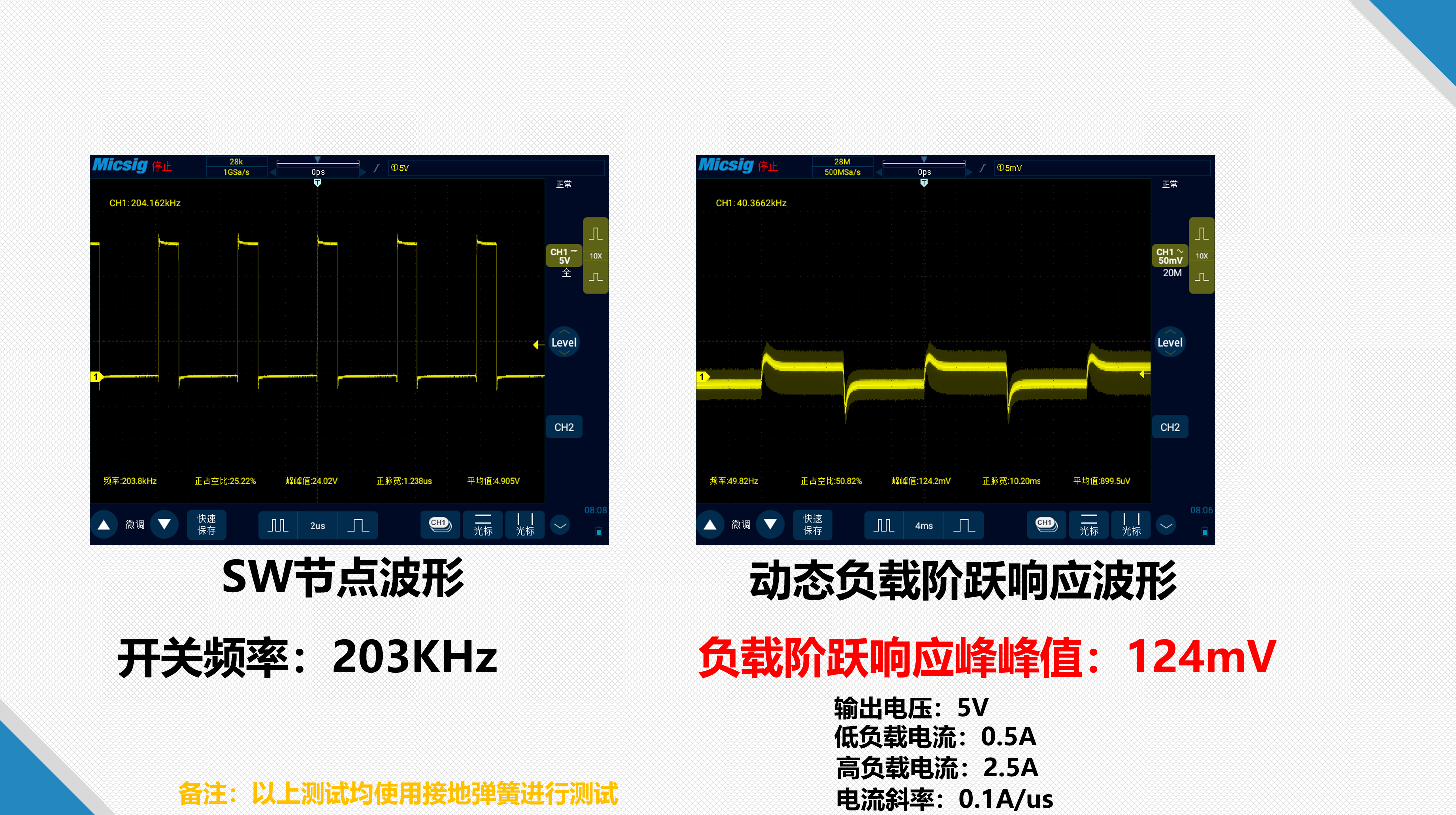 The switching node waveform is normal with no obvious ringing. The dynamic load step response is approximately 2.5%, which is average performance, not very good. The bandwidth appears low, and the parameters need further adjustment.
 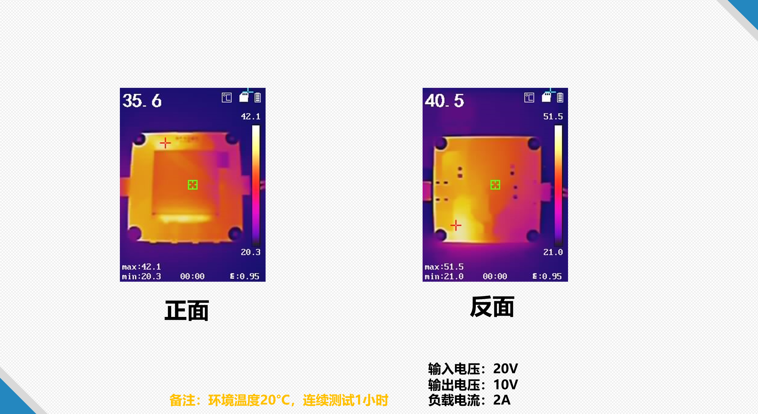 The low-load temperature is shown in the image above and is not too high. The high-temperature area is not in the power section. The LDO (Light Detector) section has the highest temperature, likely due to the high backlight current of the screen. The LDO's higher voltage
 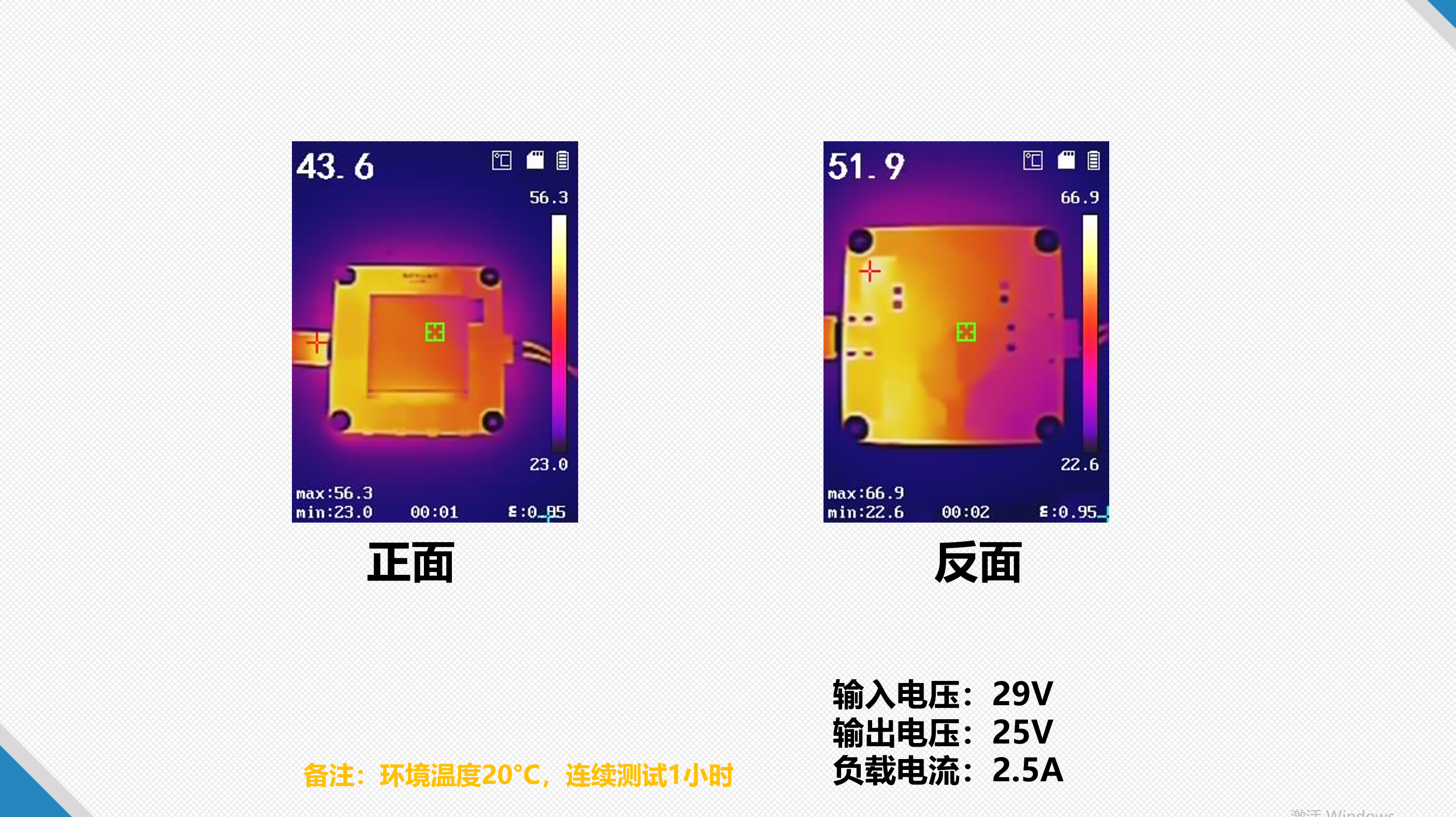 drop results in a higher temperature under high load, as shown in the graph above. The power section's temperature is significantly higher under lower load. The hottest area is the PD (Power Delivery) protocol chip, possibly due to its high input voltage, exceeding the maximum voltage specified in the datasheet.
  With a relatively small input-output voltage difference, high efficiency can be achieved; with a 20V input and 18V output, efficiency can reach approximately 97%.
All reference designs on this site are sourced from major semiconductor manufacturers or collected online for learning and research. The copyright belongs to the semiconductor manufacturer or the original author. If you believe that the reference design of this site infringes upon your relevant rights and interests, please send us a rights notice. As a neutral platform service provider, we will take measures to delete the relevant content in accordance with relevant laws after receiving the relevant notice from the rights holder. Please send relevant notifications to email: bbs_service@eeworld.com.cn.
It is your responsibility to test the circuit yourself and determine its suitability for you. EEWorld will not be liable for direct, indirect, special, incidental, consequential or punitive damages arising from any cause or anything connected to any reference design used.
Supported by EEWorld Datasheet
EEWorld
subscription
account

EEWorld
service
account

Automotive
development
community

Robot
development
community

About Us Customer Service Contact Information Datasheet Sitemap LatestNews


Room 1530, 15th Floor, Building B,
No.18 Zhongguancun Street,
Haidian District,
Beijing, Postal Code: 100190
China
Telephone: 008610 8235 0740
 京公网安备 11010802033920号

 08056C103MAT9A


