SimpleLanCrack is
a simple passive network splitter used for debugging embedded devices and capturing packets.
It is only compatible with 10/100BaseT networks.
For environments requiring higher network speeds or more convenient packet capture (simultaneous bidirectional capture, etc.), a management switch supporting port mirroring, such as the TL-SG2005, is recommended.
Principle:
Essentially, it splits the data cables, with RJ1/RJ2 connected directly. Common RJ45 network cables have two connection methods (cable heads pointing upwards, towards the gold fingers):
EIA/TIA568B: 1-Orange-white, 2-Orange, 3-Green-white, 4-Blue, 5-Blue-white, 6-Green, 7-Brown-white, 8-Brown.
EIA/TIA568A: 1-Green/White, 2-Green, 3-Orange/White, 4-Blue, 5-Blue/White, 6-Orange, 7-Brown/White, 8-Brown,
meaning Pair 2 (Orange) and Pair 3 (Green) are swapped. A straight-through cable has T568B connectors at both ends, while a crossover cable has one T568A connector and one T568B connector. Straight-through cables are more common; crossover cables are only used for interconnecting devices at the same level (switch to switch, terminal to terminal). However, most modern network port chips support polarity changes (MDIX), so straight-through cables are sufficient.
Data cable function definitions:
1: Data output, polarity +
2
: Data output, polarity - 3
: Data input, polarity + 4: NC, bidirectional data +
5: NC, bidirectional data -
6: Data input, polarity -
7: NC, bidirectional data +
8: NC, Bidirectional Data -
As you can see, pair1 (blue) and pair4 (brown) are not used in 100M networks, but transmit bidirectional data in gigabit networks. Therefore, these NC sections are used in some applications, such as PoE (wire sequence 1), where 46 is the positive power supply and 78 is the negative power supply.
RJ3/RJ4 are connected to the output/input of RJ1 respectively to provide output to external interfaces.
The two capacitors are used to interfere with the network and force the PHY to reduce the speed to 10/100BaseT. Resistors can also be used. If it can be ensured that the network will not automatically switch to 1000BaseT, the capacitors do not need to be soldered.
Passive splitters will reduce signal quality to some extent. Therefore, it is recommended to use shorter, high-quality network cables for connection.
Source:
This project is based on the open-source project of greatscottgadgets, with slight modifications to its appearance.
This project should actually inherit the open-source license of the original project. Since no relevant open-source license information from the original author was found, the open-source license of this project is tentatively set to MIT, which may change in the future. The overall
construction
is very simple,
soldering 4 RJ45s. The original author used Amphenol. RJHSE-5080/RJHSE-5380, this project is based on C2828082, which is not recommended. I just happened to have some of this model with LEDs left over.
For the capacitors, the original author used a 220pF KEMET C315C221K1G5TA monolithic capacitor. This project is compatible with both 100mil and C0805 through-hole packages. A C0G (NP0) 220pF capacitor is recommended. The original 100VDC
connector did not have shielded interfaces. In this diagram, the four RJ45 shields are interconnected and connected to the screw holes. There will be no difference in actual use.
Ensure
the router/switch network is available. Connect via network cable:
Switch <---> RJ1 -- RJ2 <---> Embedded device.
At this point, the splitter is only equivalent to one segment of the network cable, and the embedded device should be able to communicate normally. If communication fails, check the network/line
. Connect the PC's network port to RJ3 or RJ4 as needed to capture input data packets. At this time, the PC's network port is only a passive receiving port and has no output capability (output signal line 12 is not connected).
Use open-source Wireshark or other host computer software on the PC to capture the input data packets of the corresponding network port; this is the actual unidirectional data packet content on the link.
The casing
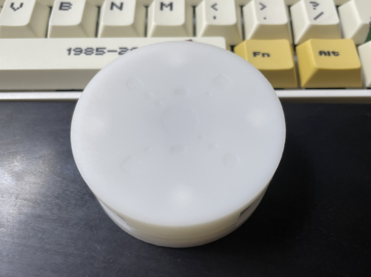
uses the EDA's built-in casing design; a rounded shape looks better. The dots on top indicate straight-through, and the square ports are for monitoring. Using colored pens to make raised dots would be better.

I'm not very good at EDA design, so there are a few issues:
As shown in the image above, the distance between the bottom shell and the bottom edge of the network port isn't right. It doesn't affect usability, and I'm too lazy to fix it.
There's a tiny gap between the top and bottom shells; it might look nice as a dark-colored trim after some wear and tear (not really).
The support posts for the screw holes inside the bottom shell are too short and don't reach the PCB. The positioning posts for the network port are supported on top of the bottom shell (actually, the above two issues are also due to this; I don't want to cut the support posts, as it would look even worse if it's uneven)
. I don't know how to add clips in EDA, so I used top and bottom studs to press down on the PCB for fixation (even though the design is a bit short). Then, I used glue to fix the top and bottom shells at the interface.


 京公网安备 11010802033920号

 L1360
L1360


