Note: The original design was for Altium Designer 24. Considering the target audience, it was manually ported (re-drawn) to JLCPCB EDA, discarding some unnecessary components.
There are some differences from the original AD24 project.
Production process and introduction video: https://www.bilibili.com/video/BV1fCxqebEiP/
AD24 open source files can be found in the video introduction section
. I. Basic Parameters
Power Supply: USB PD 2.0/3.0, 9-20V (can directly use a USB-C connector without data to input DC power, maximum 24V)
Output Power: 40W/20W*2 (20V power supply, 4 ohms/8 ohms), 15W/7.5W*2 (12V power supply, 4 ohms/8 ohms), please refer to Fig. 13 and Fig. 14 in the TPA3116D2 datasheet for details.
Input Signal: USB: UAC1.0 maximum 96KHz/24bit, driverless for win10/win11/Android/iOS/MacOS/Linux Bluetooth: Bluetooth 5.4, LDAC/aptX/aptX-HD/aptX adaptive (Bluetooth priority)
PCB size: 65.8x30 (mm), height depends on the actual height of the electrolytic capacitors and the height of the heatsink.
II. Circuit Description
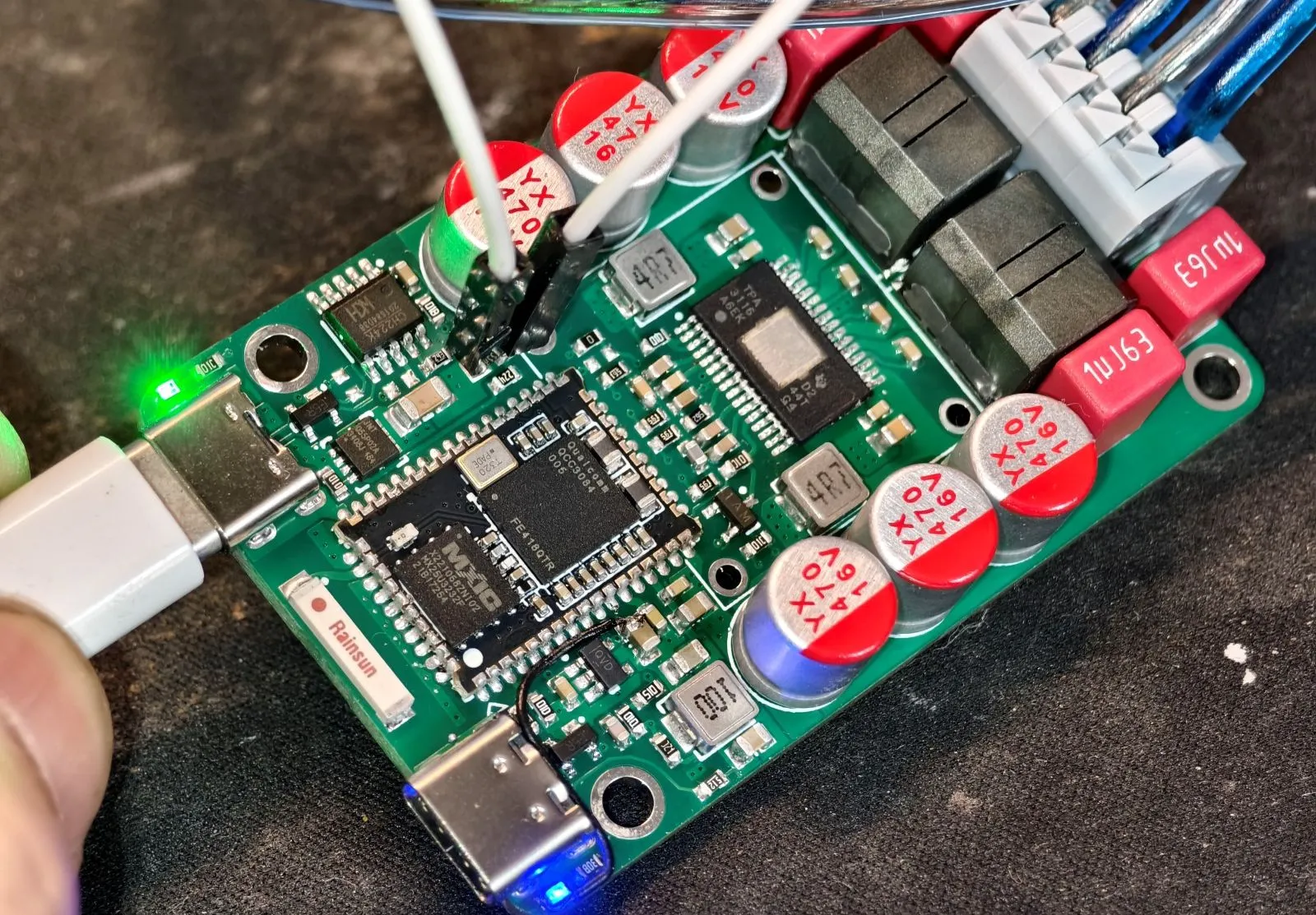
2.1 The Bluetooth module is Tianjiarun's SJR-BTM384 (QCC3084). The original AD24 project used Anlang Technology's AL3084. The two are incompatible in pins and sizes and cannot be used interchangeably. Because Anlang Technology's AL3084 module has slightly poor USB compatibility (there is a chance of prompting insufficient USB resources when connecting to a USB HUB), it was replaced with Tianjiarun. The price difference between the two is not significant. Bluetooth priority means that when both USB and Bluetooth are connected simultaneously, the Bluetooth audio stream will be played.
2.2 The USB PD spoofing is CH224K, available at LCSC online store. It uses a single resistor configuration mode, and the default circuit diagram requests 12V (R8=24K). If 20V operation is required, simply unsolder R8. Please refer to page 3 of the CH224 datasheet for details. If you don't want to buy a GaN charger, you can directly buy a Type-C cable, cut it, connect the red wire to the positive terminal of the power supply, and the black wire to the negative terminal. DC power can also be used. There is no additional identification circuit designed here; 9-24V is acceptable. Just make sure the positive and negative terminals are not reversed.
2.3 The amplifier circuit is a TPA3116D2. A heatsink can be added as needed. If using a 12V power supply to drive speakers no more than dual 15W, theoretically, a heatsink is not needed (in practice, it doesn't get hot to the touch). A recommended heatsink size is 22*13*11MM (available at Youxin Electronics, https://item.taobao.com/item.htm?id=535408058590). For gain and power limiting settings, please refer to the TPA3116D2 datasheet. If you are unsure of the purpose of these functions, it is recommended not to modify them. The gain is 26dB (20x), which matches the output signal level of the QCC3084. Since I don't use LCSC EDA much, I'm not sure how to represent NC, so R8 is set to request 12V. For a gain of 26dB, it's recommended to use a 20V power supply (i.e., don't solder R8), otherwise the 26dB gain + 12V power supply will cause distortion after the volume exceeds halfway.
2.4 The power switch is a P-channel MOSFET. Shorting the PWR pin on the front of the PCB will start the power supply. If you need automatic startup, short the MOSFET DS or directly solder PWR together using a jumper wire.
2.5 The power indicator is constantly lit (near the power input USB-C port; it will light up as long as the PD receives voltage, regardless of whether PWR is shorted). The Bluetooth indicator (near the data input USB-C port) is dual-color: blue indicates Bluetooth is connected, slow blue flashing indicates not connected, fast blue flashing indicates entering pairing mode, and green indicates USB is connected.
2.6 No volume potentiometer is provided. Please adjust the volume using a computer or mobile phone (because potentiometers consume a lot of PCB space, this design prioritizes small size, and potentiometers have poor durability; over time, the slider may become unresponsive).
2.7 The terminal block is KF250-3.5-4P-1, which can accommodate wires with a maximum outer diameter of 3mm. A conductor cross-sectional area of 1.5mm² or less is recommended.
2.8 The PCB has 4 layers; layer stack-up and impedance are not critical. USB 1.1 12Mbps does not require impedance considerations; if it connects, it works.
2.9 USB-C does not support mixed use; that is, signal and power inputs are separated. The port marked "Power" on the back is for power input and does not support signal input. The port marked "DATA" on the back is for signal input and does not support power input, but it includes a UFP identification resistor. It can directly connect to a laptop or mobile phone using a dual-C cable to transmit UAC protocol audio data. Because there is no physical power supply, it will not steal power from the computer or mobile phone. (
Too long, don't read version):
If you are using 20V power, do not solder R8 (see the USB_PD diagram, default is 24K). Maximum power is 40W (4 ohms) for both, and 20W (8 ohms) for both.
If you are using 12V power, please modify the resistors as follows: R25 = do not solder, R26 = 5.6K, R24 = 24K (R24 is recommended to be changed, but not changing it is not a big problem). Maximum power is 15W (4 ohms) for both, and 7.5W (8 ohms) for both.
Some parts of the explanation may not be clear; please refer to video P2 for circuit explanation. If you still have questions, please leave a comment or send a private message. I don't check JLCPCB messages frequently.


 京公网安备 11010802033920号

 2SB1518JHUL


