Video Link:
Bilibili Video -- Function Demonstration and
Project Introduction
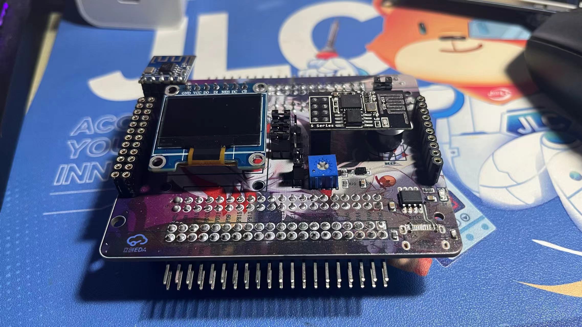
This expansion board is a learning expansion board based on the GD32F407VET6. It can be used by beginners to learn GD32 and master the use of related peripherals, laying the foundation for building projects. The source code implements the usage of onboard peripheral resources, controlled by macro definitions. Enabling different macro definitions allows you to see the specific phenomena.
The board has a variety of rich resources, including:
(1) SPI OLED
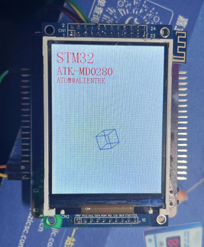
(2) 2.8-inch LCD
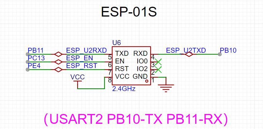
(3) ESP01-S
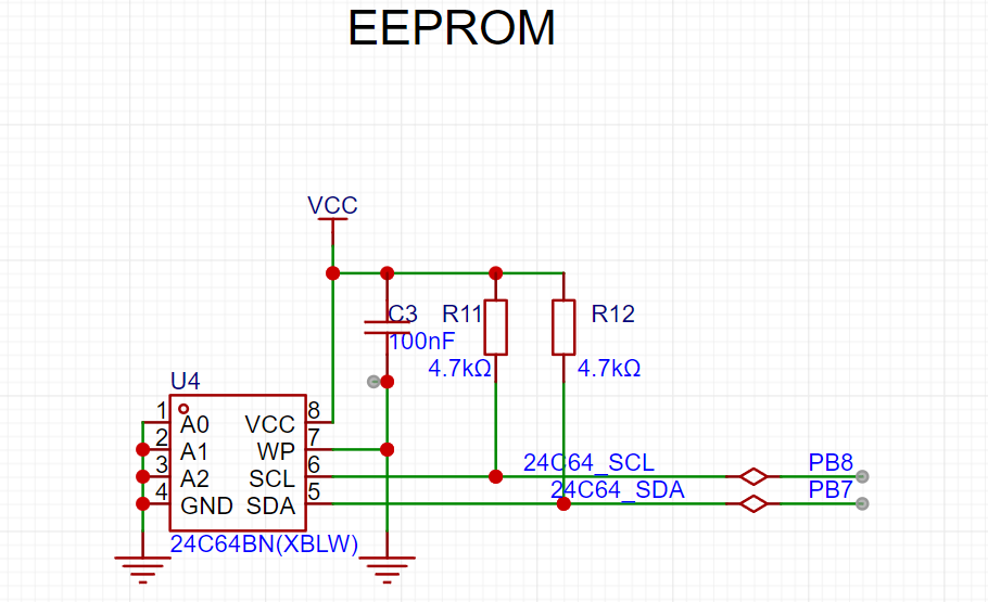
(4) EEPROM 24C64
(5) Bluetooth module
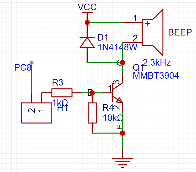
(6) Buzzer
(7) Type-C serial port
(8) ADC potentiometer
(9) Buttons
.
Onboard peripheral module usage:
(1) SPI OLED
software: SPI basic display
(2) 2.8-inch LCD
software: Simulate 8080 LCD display
(3) ESP01-S:
AP mode and STA mode .
AP mode: Send data to the microcontroller via mobile phone connection.
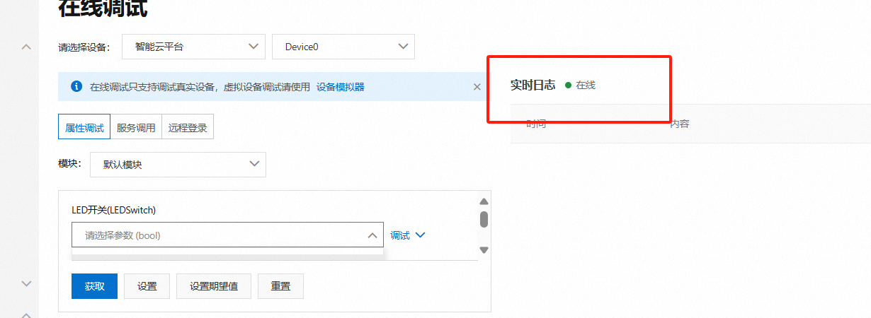
STA mode: Connect to Alibaba Cloud, and Alibaba Cloud can issue commands to control the LED
(4) EEPROM 24C64
: Read data
(5) Bluetooth module:
Control LED via Bluetooth.
(6) Buzzer
: The buzzer sounds a prompt.
(7) Type-C Serial Port
: Data can be sent and received with the host computer via a Type-C data cable.
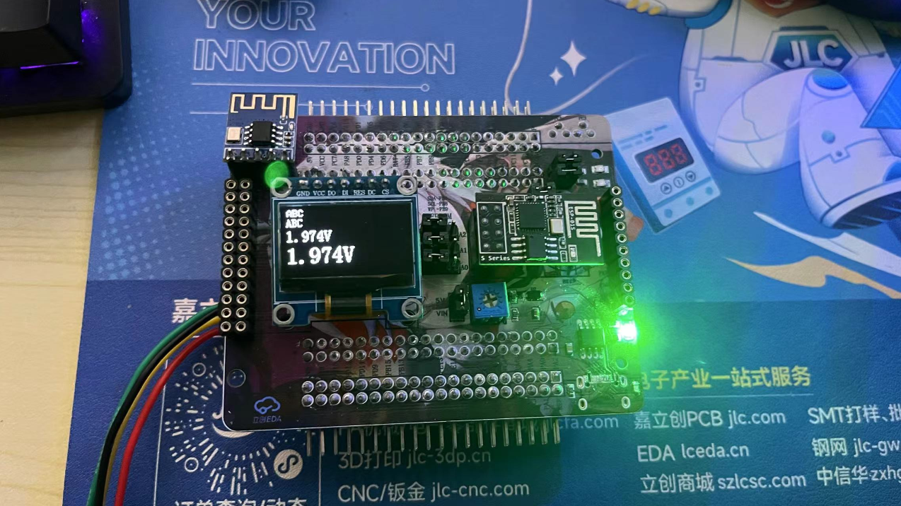
(8) ADC Potentiometer
: The input voltage can be adjusted by adjusting the potentiometer.
(9) Button:
Used to control custom functions.
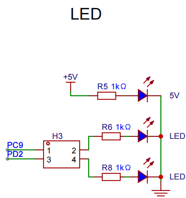
(10) LED Indicator:
Two-way LED indicator
principle analysis (hardware description)
1. Expansion Pin Header:
All pins are brought out through the pin header for easy expansion

. 2. SPI OLED: The
OLED is connected to the hardware SPI pin for easy use of software/hardware SPI driver

. 3.
LCD: CN1 of the LCD is connected to the FMC interface, and CN2 is connected to the SPI. The display can be driven by 8080 or SPI through FMC.

4. ESP01S
Communication Connection: Serial port PB10/PB11.
5. EEPROM:
SCL and SDA are pulled up to VCC for easy use of hardware IIC and configuration of open-drain output.
6. Bluetooth Module :
The Bluetooth module is connected to the serial port.

7. BEEP
Buzzer: Connect the buzzer to PC8 through a jumper cap, or connect it to other pins through a curved jumper cap. PC8 has PWM
. 8. Type-C CH340N
connects to Type-C, allowing direct connection to a computer using a Type-C cable. CH340N is also compatible with the best soldering .

9. Potentiometer:
The potentiometer is connected to 5V via a jumper cap for voltage input measurement.

10. Buttons: The board
has four buttons. Since there is no hardware pull-up, a pull-up input needs to be configured.

11. LEDs:
Two LED indicators are connected to fixed pins via jumper caps, or DuPont wires can be used.
Software code
enables different experiments through macro definitions.
#include "board.h"
#include "demo.h"
AP_PARAMETER ap_parameter={0};
uint8_t test_ret = 0;
uint16_t value = 0;
unsigned char dat1 = 0;
unsigned char dat2 = 0;
float valueVet = 0;
char str[40] = {0};
#define WIFI_AP_TEST 0
#define WIFI_STA_TEST 0
#define ADC_TEST 1
#define EEPROM_TEST 0
#define LCD_TEST 1
#define OLED_TEST 0
int main(void)
{
board_init();
bsp_led_init();
bsp_uart_init();
WIFI_ESP01S_Init();
printf("start
");
#if OLED_TEST
OLED_Init(); //Initialize OLED
OLED_Clear();
#endif /* OLED_TEST */
#if WIFI_AP_TEST
bsp_gpio_on(WIFI_EN);
bsp_gpio_off(WIFI_RST);
delay_ms(100);
bsp_gpio_on(WIFI_RST);
WIFI_MODE_AP_Init();
#endif /* WIFI_AP_TEST */
#if WIFI_STA_TEST
bsp_gpio_on(WIFI_EN);
bsp_gpio_off(WIFI_RST);
delay_ms(100);
bsp_gpio_on(WIFI_RST);
WIFI_MODE_STA_Aliyun_Init();
#endif /* WIFI_STA_TEST */
#if ADC_TEST
bsp_adc_init();
#endif /* ADC_TEST */
#if EEPROM_TEST
i2c_test();//There is a problem
#endif /* EEPROM_TEST */
#if LCD_TEST
/* LCD display */
demo_run(); /* Run the example program */
#endif /* LCD_TEST */
while(1)
{
memset(str,0,sizeof(str)); // Clear the 0 array for later use
value = Get_ADC_Value(CHANNEL_ADC);
printf("value = %d
", value );
valueVet = (value * 3300 >> 12) * (R2 + R1)/R1/1000.0;
sprintf(str, "%.3fV ", valueVet);
printf("voltage = %f V
", valueVet );
OLED_ShowString(0,0,(uint8_t *)"ABC",8,1);//6*8 “ABC”
OLED_ShowString(0,8,(uint8_t *)"ABC",12,1);//6*12 “ABC”
//OLED_ShowString(0,20,(uint8_t *)str,16,1);//8*16 “ABC”
OLED_ShowString(0,36,(uint8_t *)str,24,1);//12*24 “ABC”
OLED_Refresh();
#if WIFI_AP_TEST
//Check if there is a device connected
Get_Device_connection_status();
//delay_ms(500);
bsp_led_toggle(LED1);
//bsp_gpio_toggle(BEEP);
bsp_led_toggle(LED2);
//If the current device is connected to the server (mobile APP is connected to the hotspot)
if( wifi_link_flag == 2 )
{
if( Get_WIFI_AP_Data(&ap_parameter) == 1 )//If data is received
{
//Output the received data
// printf("ID = %d
", ap_parameter.device_id );//Device ID
// printf("data len = %d
", ap_parameter.device_datalen );//Length of the data sent
// printf("data = %s
", ap_parameter.device_data );//Data sent
sprintf(str, "%s", ap_parameter.device_data);
OLED_ShowString(0,20,(uint8_t *)str,16,1);//8*16 “ABC”
memset(str,0,sizeof(str)); // Clear the array to 0 for later use
//delay_ms(500);
}
}
#endif /* WIFI_AP_TEST */
delay_ms(500);
}
}
Notes:
This section can be used to fill in points that require special attention during design and production, or areas prone to errors. Examples:
1. The color silkscreen printing was unclear; this has been corrected in the project
. 2. It is recommended to solder the four fixing pins of the Type-C port on both sides. I accidentally removed mine, damaging the circuit board and causing communication errors. Actual
product images :
1. Front view of the actual product
2. Back view of the actual product

3. LCD
4. ADC
5. Type-C serial port output

6. Alibaba Cloud connection
WIFIAP.mp4
ADC.mp4
gd32_TEST.rar
PDF_GD32F407VETE Learning Extension Board.zip
Altium_GD32F407VETE Learning and Extension Board.zip
PADS_GD32F407VETE Learning and Extension Board.zip
BOM_GD32F407VETE Learning and Extension Board.xlsx
91684
Desktop Ornament - Network Clock
This design is a network clock desktop ornament based on the LCSC STM32F103C8T6 development board.
It has four independent buttons, each with the following function: it can adjust the alarm timer, and when the timer reaches the set time, it will sound an alarm.
Video Link:
[Bilibili Video - Function Demonstration and Introduction](【Desktop Ornament - Network Clock - STM32 - ESP01S】 https://www.bilibili.com/video/BV1vpmLYFEbE/?share_source=copy_web&vd_source=9018d111288e591392312c7d0a656c8a)
Project Introduction:
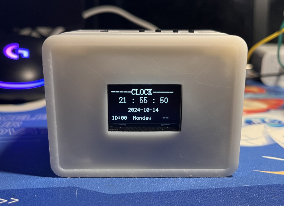
This project is a network clock based on the LCSC development board DiKuoXing STM32F103C8T6, using the RTX real-time operating system. It displays the time on a 4-pin IIC OLED, obtains the time from the network via the EPS01S, is powered by a lithium battery, and charges via a Type-C port. An alarm clock function is included, with the number of alarms controllable via macros and having no upper limit. An alarm is activated via a buzzer.
Project Functionality
This design is based on the network clock of the LCSC development board Dikuoxing STM32F103C8T6;
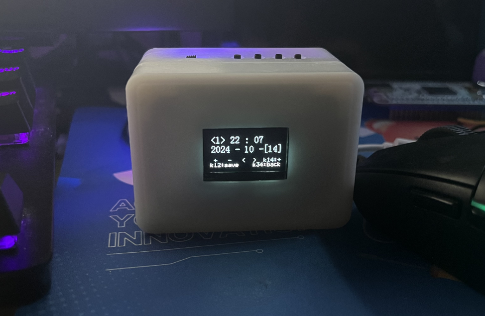
it has four independent buttons, and the function of each button is defined as follows: it can realize the adjustment of the alarm clock timer, and when the time reaches the set time, it will sound a buzzer to remind.
Clock interface button definition:
K1: View alarm clock 1~N (5)
K2: Turn on/off buzzer
K3: Turn on/off heartbeat light
K4: Undefined
K1K2: Undefined
K1K4: Restart
K3K4: Switch alarm clock interface
Alarm clock interface button definition:
K1: Add
K2: Subtract
K3: Move left to select
K4: Move right to select
K1K2: Save alarm clock
K1K4: Switch saved alarm clock
K3K4: Switch clock interface
Project Parameters
This design uses STM32F103C8T6 as the main controller;
this design uses 4-pin IIC The OLED display shows the current time, date, and day of the week;
a buzzer is used for alarm clock notification;
the wireless module is EPS-01S;
it features four buttons, with various functions achieved through different button combinations;
an onboard LED serves as a heartbeat indicator, which can be turned off by a button.
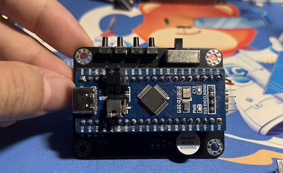
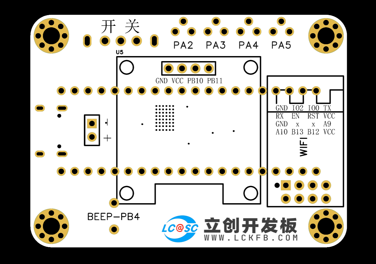
Hardware Explanation:

Main Control and Power Supply:
Utilizes an STM32F103C8T6 microcontroller with a TYPE-C-16P power

supply. Charging/Discharging Circuit:
Uses a TYPE-C-16P interface as the power supply interface, simultaneously charging the lithium battery. A switch controls whether to use lithium battery power. The circuit automatically switches to lithium battery power when the external power supply is disconnected, ensuring stable power supply.
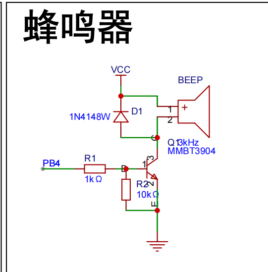
Buzzer Circuit:
The buzzer is controlled by the high and low levels of PB4.
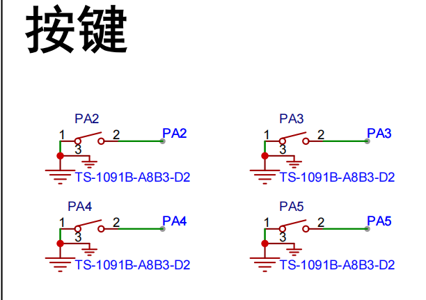
Button circuit:
Configured with four buttons, configured as pull-up input.
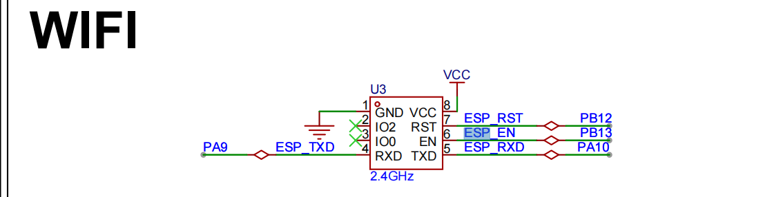
Wireless module circuit:
Connects to serial port 1, PA9, PA10.

Display circuit:
SDA connects to PB11, SCL connects to PB10, using hardware IIC driver
software code
. /**************************** STA mode ****************************/
//In STA mode, the hotspot the WIFI module needs to connect to (you need to modify it to your own parameters)
#define WIFISSID "ChinaNet-nkY6" //Wi-Fi hotspot name
#define WIFIPASS "97spky4v" //Wi-Fi hotspot password
Assembly process:
Flowchart of actual assembly
1. All modules
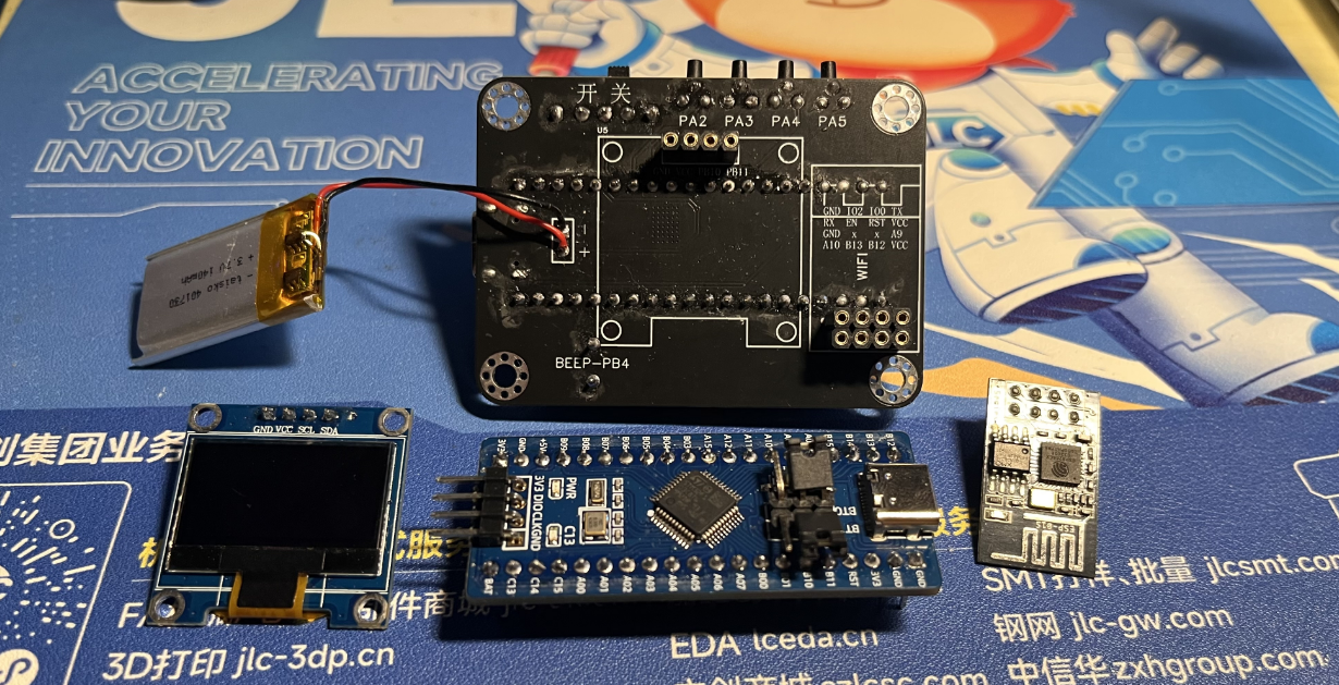
2. Install main controller
3. Packaging and battery protection

4. Install OLED and WIFI module

5. Power on and light up the chip

6. Install into the shell and screw in the screws Actual picture: Complete

actual
picture. For better aesthetics later, a panel can be added, with a pre-reserved groove.

V4-402_RTX_Network Clock.rar
PDF_Desktop Ornaments - Online Clock.zip
Altium Desktop Decor - Network Clock.zip
PADS_Desktop Ornaments - Network Clock.zip
BOM_Desktop Decor - Network Clock.xlsx
91685
electronic


 京公网安备 11010802033920号

 MLP12-1330-FT452Q


